Downloaded 34 times


![17
Powersplitter
Powercombiner
Power
splitter
Power
splitter
RL
RG
f0
Pin
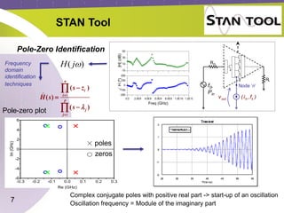
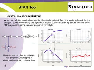
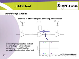
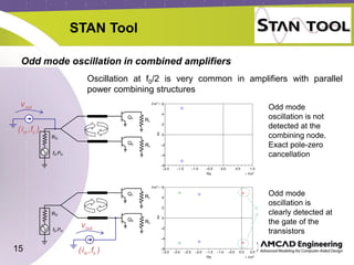
STAN Tool
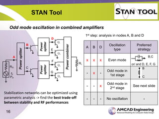
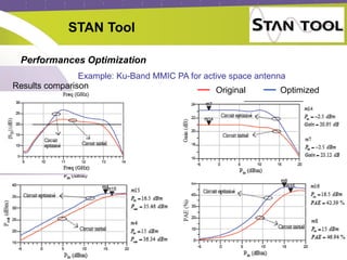
Odd mode oscillation in combined amplifiers
Test of the 4 branches with 4 probes, changing the phase
Odd mode oscillation
[ + - - +] or [ + - + - ]
Q1 oscillates out of
phase with Q2, same for
Q3 and Q4
Powersplitter
Powercombiner
Power
splitter
Power
splitter
RL
RG
f0
Pin
Q1
Q2
Q3
Q4
Powersplitter
Powercombiner
Power
splitter
Power
splitter
RL
RG
f0
Pin
Q1
Q2
Q3
Q4
Powersplitter
Powercombiner
Power
splitter
Power
splitter
RG
f0
Pin
Q1
Q2
Q3
Q4
Powersplitter
Powercombiner
Power
splitter
Power
splitter
RG
f0
Pin
Q1
Q2
Q3
Q4
Odd mode oscillation
[ + + - - ]
Q1 and Q2 oscillates out
of phase with Q3 and Q4
Powersplitter
Powercombiner
Power
splitter
Power
splitter
R
RG
f0
Pin
Q1
Q2
Q3
Q4
Powersplitter
Powercombiner
Power
splitter
Power
splitter
RG
f0
Pin
Q1
Q2
Q3
Q4Powersplitter
Powercombiner
Power
splitter
Power
splitter
RL
RG
f0
Pin](https://image.slidesharecdn.com/stanoverview-161003102559/85/STAN-Tool-overview-17-320.jpg)


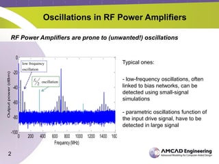
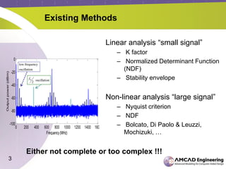
The document discusses the stability analysis of microwave circuits, particularly focusing on low-frequency oscillations in RF power amplifiers. It outlines existing methods for detecting oscillations, their limitations, and presents the STAN tool for linear and non-linear stability analysis. The tool aids in identifying oscillation modes and applying suitable stabilization strategies to improve amplifier performance.
![RF Module Design - [Chapter 4] Transceiver Architecture](https://cdn.slidesharecdn.com/ss_thumbnails/rfch4-150613070346-lva1-app6891-thumbnail.jpg?width=640&height=640&fit=bounds)


![RF Module Design - [Chapter 6] Power Amplifier](https://cdn.slidesharecdn.com/ss_thumbnails/rfch6-150613070347-lva1-app6891-thumbnail.jpg?width=640&height=640&fit=bounds)


![Multiband Transceivers - [Chapter 4] Design Parameters of Wireless Radios](https://cdn.slidesharecdn.com/ss_thumbnails/ch4-150613070934-lva1-app6892-thumbnail.jpg?width=640&height=640&fit=bounds)


![RF Circuit Design - [Ch4-1] Microwave Transistor Amplifier](https://cdn.slidesharecdn.com/ss_thumbnails/ch4-1-150613064409-lva1-app6892-thumbnail.jpg?width=640&height=640&fit=bounds)


![Agilent ADS 模擬手冊 [實習3] 壓控振盪器模擬](https://cdn.slidesharecdn.com/ss_thumbnails/3adsosc-150613072819-lva1-app6892-thumbnail.jpg?width=640&height=640&fit=bounds)