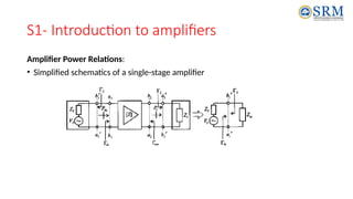
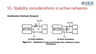
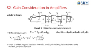
18ECE304T-MICROWAVE INTEGRATED CIRCUITS
UNIT III- Microwave Amplifiers and Oscillators
S1- Introduction to amplifiers, Stability considerations in active networks
S2- Gain Consideration in Amplifiers,
S3- Noise Consideration in active networks
Dr.S. Bashyam
Assistant Professor
Department of ECE, SRM IST
S1- Introduction to amplifiers
• Amplifier designs at RF differ significantly from the conventional low-frequency
circuit approaches and consequently require special considerations.
• Appropriate matching is needed to reduce the VSWR and avoid undesirable
oscillations.
• stability analysis in conjunction with gain and noise figure circles, is a basic
ingredient needed to meet the often competing requirements of gain, gain
flatness, output power, bandwidth, and bias conditions
S1- Introduction to amplifiers
Generic Amplifier System:
• A generic single-stage amplifier configuration embedded between input and output
matching networks is shown below.
• Input and output matching networks, are needed to reduce undesired reflections and thus
improve the power flow capabilities.
• Amplifier is characterized through its S-matrix at a particular DC bias point
S1- Introduction to amplifiers
Key Parameters:
• Gain and gain flatness (in dB)
• Operating frequency and bandwidth (in Hz)
• Output power (in dBm)
• Power supply requirements (in V and A)
• Input and output reflection coefficients (VSWR)
• Noise figure (in dB)
• Also parameters such as intermodular distortion (IMD) products, harmonics,
feedback, and heating effects, all of which can seriously affect the amplifier
performance.
S1- Introduction to amplifiers
Amplifier Power Relations:
• Simplified schematics of a single-stage amplifier
S1- Introduction to amplifiers
Problem:
S1- Introduction to amplifiers
S1- Stability considerations in active networks
Stability Circles:
• The phenomenon of oscillations can be understood in the context of a voltage
wave along a transmission line.
• If , then the return voltage increases in magnitude (positive feedback)
causing instability.
• Conversely, causes a diminished return voltage wave (negative feedback).
• Let us regard the amplifier as a two-port network characterized through its S
parameters and external terminations described by .
• Stability then implies that the magnitudes of the reflection coefficients are less
than unity. Namely,
S1- Stability considerations in active networks
Stability Circles:
S1- Stability considerations in active networks
Unconditional Stability Circles:
S1- Stability considerations in active networks
Stability Factor:
• It is always prudent to determine that both the conditions are
fulfilled to ensure an unconditionally stable design.
S1- Stability considerations in active networks
Stabilization Methods(Input):
S1- Stability considerations in active networks
Stabilization Methods (Output):
S2- Gain Consideration in Amplifiers
Unilateral Design:
• Unilateral power gain: or
• where Gs and GL are gains associated with input and output matching networks and Go is the
insertion gain of the transistor
S2- Gain Consideration in Amplifiers
Problem:
S2- Gain Consideration in Amplifiers
Unilateral Figure of Merit Error Fluctuation
Problem 2:
S2- Gain Consideration in Amplifiers
Bilateral Design:
• For many practical situations the unilateral approach may not be appropriate
because the error committed by setting S12 = 0 could result in an intolerably
imprecise design.
• The bilateral design takes into account this feedback
S3- Noise Consideration in active networks
Noise Figure Circles:
• In many RF amplifiers, the need for signal amplification at low noise level
becomes an essential system requirement.
• Unfortunately, designing a low-noise amplifier competes with such factors as
stability and gain.
• For instance, a minimum noise performance at maximum gain cannot be
obtained.
• It is therefore important to develop a method that allows us to display the
influence of noise as part of the Smith Chart to conduct comparisons and observe
trade-offs between gain and stability.
S3- Noise Consideration in active networks
Noise Figure Circles:
• From a practical perspective, the key ingredient of a noise analysis is the noise
figure of a two-port amplifier in the admittance form
or in the equivalent impedance representation
where Zs = l/Ys is the source impedance
S3- Noise Consideration in active networks
• When using transistors, typically four noise parameters are known either through
datasheets from the FET or BJT manufacturers or through direct measurements.
They are:
References
1. RF circuit design Theory and applications, Reinhold Ludwig, Pavel Bretchko

Unit_3_S1,2,3_18ECE304T -MICROWAVE INTEGRATED CIRCUITS.pptx

  • 1.
    18ECE304T-MICROWAVE INTEGRATED CIRCUITS UNITIII- Microwave Amplifiers and Oscillators S1- Introduction to amplifiers, Stability considerations in active networks S2- Gain Consideration in Amplifiers, S3- Noise Consideration in active networks Dr.S. Bashyam Assistant Professor Department of ECE, SRM IST
  • 2.
    S1- Introduction toamplifiers • Amplifier designs at RF differ significantly from the conventional low-frequency circuit approaches and consequently require special considerations. • Appropriate matching is needed to reduce the VSWR and avoid undesirable oscillations. • stability analysis in conjunction with gain and noise figure circles, is a basic ingredient needed to meet the often competing requirements of gain, gain flatness, output power, bandwidth, and bias conditions
  • 3.
    S1- Introduction toamplifiers Generic Amplifier System: • A generic single-stage amplifier configuration embedded between input and output matching networks is shown below. • Input and output matching networks, are needed to reduce undesired reflections and thus improve the power flow capabilities. • Amplifier is characterized through its S-matrix at a particular DC bias point
  • 4.
    S1- Introduction toamplifiers Key Parameters: • Gain and gain flatness (in dB) • Operating frequency and bandwidth (in Hz) • Output power (in dBm) • Power supply requirements (in V and A) • Input and output reflection coefficients (VSWR) • Noise figure (in dB) • Also parameters such as intermodular distortion (IMD) products, harmonics, feedback, and heating effects, all of which can seriously affect the amplifier performance.
  • 5.
    S1- Introduction toamplifiers Amplifier Power Relations: • Simplified schematics of a single-stage amplifier
  • 6.
    S1- Introduction toamplifiers Problem:
  • 7.
  • 8.
    S1- Stability considerationsin active networks Stability Circles: • The phenomenon of oscillations can be understood in the context of a voltage wave along a transmission line. • If , then the return voltage increases in magnitude (positive feedback) causing instability. • Conversely, causes a diminished return voltage wave (negative feedback). • Let us regard the amplifier as a two-port network characterized through its S parameters and external terminations described by . • Stability then implies that the magnitudes of the reflection coefficients are less than unity. Namely,
  • 9.
    S1- Stability considerationsin active networks Stability Circles:
  • 10.
    S1- Stability considerationsin active networks Unconditional Stability Circles:
  • 11.
    S1- Stability considerationsin active networks Stability Factor: • It is always prudent to determine that both the conditions are fulfilled to ensure an unconditionally stable design.
  • 12.
    S1- Stability considerationsin active networks Stabilization Methods(Input):
  • 13.
    S1- Stability considerationsin active networks Stabilization Methods (Output):
  • 14.
    S2- Gain Considerationin Amplifiers Unilateral Design: • Unilateral power gain: or • where Gs and GL are gains associated with input and output matching networks and Go is the insertion gain of the transistor
  • 15.
    S2- Gain Considerationin Amplifiers Problem:
  • 16.
    S2- Gain Considerationin Amplifiers Unilateral Figure of Merit Error Fluctuation Problem 2:
  • 17.
    S2- Gain Considerationin Amplifiers Bilateral Design: • For many practical situations the unilateral approach may not be appropriate because the error committed by setting S12 = 0 could result in an intolerably imprecise design. • The bilateral design takes into account this feedback
  • 18.
    S3- Noise Considerationin active networks Noise Figure Circles: • In many RF amplifiers, the need for signal amplification at low noise level becomes an essential system requirement. • Unfortunately, designing a low-noise amplifier competes with such factors as stability and gain. • For instance, a minimum noise performance at maximum gain cannot be obtained. • It is therefore important to develop a method that allows us to display the influence of noise as part of the Smith Chart to conduct comparisons and observe trade-offs between gain and stability.
  • 19.
    S3- Noise Considerationin active networks Noise Figure Circles: • From a practical perspective, the key ingredient of a noise analysis is the noise figure of a two-port amplifier in the admittance form or in the equivalent impedance representation where Zs = l/Ys is the source impedance
  • 20.
    S3- Noise Considerationin active networks • When using transistors, typically four noise parameters are known either through datasheets from the FET or BJT manufacturers or through direct measurements. They are:
  • 21.
    References 1. RF circuitdesign Theory and applications, Reinhold Ludwig, Pavel Bretchko