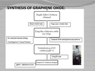
Nitrogen Enriched Carbon Coated
Chemically Modified Graphene Scaffold
For Capacitive Energy Storage
  
 
By:
Abubakar Sadique
Sunil Kanamarlapudi
Pooja Sahare
Soundarya K.
 
OUTLINE
Graphene
Super Capacitor
Graphene Oxide
Objectives
Experimental Procedure
Characterization and Results
Conclusions
Graphene
Graphene is a single tightly packed layer of carbon
atoms that are bonded together in a hexagonal
honeycomb lattice.
Layers of Graphene stacked on top of each other
form graphite , with an inter planar spacing of 0.335
nano metres.
The lightest material known (with 1 square meter
coming in at around 0.77 milligrams),
The strongest compound discovered (between 100-
300 times stronger than steel)
The best conductor of electricity known
Properties of Graphene
PROPERTY RANGE
Theoretical specific surface area 2630 m2 g-1
Young’s modulus 1 T pa
Fracture strength 120 M pa
Carrier mobility at room temperature 10,000 cm2 V-1 S-1
Optical transmittance 97.7%
Electrical conductivity 5000 W m-1 K-1
Specific capacity 80 mF cm-2
Specific capacitance 550 F g-1
Charge Storage
Graphene as Super capacitor
Graphene has substantially more
relative surface area.
Thus, as a super capacitor material
it will be better at storing
electrostatic charge.
Material made up of one single
atomic layer, it is lighter.
Ecologically friendly, unlike
most other forms of energy
storage.
Graphene Oxide (GO):
Structurally, GO can be visualized as a graphene sheet with its
basal plane decorated by oxygen-containing groups.
Due to high affinity to water molecules by these groups, GO is
hydrophilic and can be dissolved in water.
The solubility in water makes the deposition of the thin films of
the GO straightforward.
GO is a poor conductor but its chemical treatment by light,
heat, or chemical reduction can restore most properties of the
famed pristine graphene.
OBJECTIVES:
The modified Hummer’s hydrothermal method was employed to prepare
reduced Graphene oxide using the exfoliated graphite.
Chemically modify reduced Graphene oxide by enriching with nitrogen
and coating with carbon sources.
Characterize the different types of samples for different properties such as
morphology, conductance, electrochemical properties, absorbance, and
zeta potential.
EXPERIMENTAL PROCEDURE
Exfoliated Graphite(EG): Carbon content=99%,
Apparent Density=0.0025g/cc
Graphite Nano Pellets(GNP): Carbon content=99%,
Apparent Density=0.06g/cc
H2SO4: As a medium for oxidizer
KMnO4: As an oxidizer
H2O2: To remove excess KMnO4
HCl: To remove the manganese salts
DI water: For dilution and neutralizing
MATERIALS AND THEIR PROPERTIES:
PREPARATION OF GRAPHITE NANO PLATELETS (GNPs):
SYNTHESIS OF GRAPHENE OXIDE:
KMnO4+ 3H2SO4K+
+MnO3+ + H3O+ +
3HSO4-
MnO3+ + MnO4-  Mn2O7
SYNTHESIS OF GRAPHENE OXIDE:
SYNTHESIS OF RGOD-Reduced Graphene oxide C coated
with D-Glucose:
SYNTHESIS OF RGODE-Reduced Graphene oxide ‘N’
enriched with (EDA) and ‘C’ coated with D-Glucose
FESEM
FE-SEM images of (a) GO (b) RGOD8(c) RGODE8 (d) RGOD20 (e) RGODE20
CHARACTERIZATION
Results of FESEM
1) GO Sample was gold sputtered as it was least conductive, and overall image
showed that it has a layered structure.
2) RGOD sample had carbon spheres due to D-glucose which was used as
carbon source for coating.
3) RGODE samples had less carbon spheres and more porous structure due to
addition of nitrogen source EDA.
4) Time of reduction of GO is directly proportional to porous morphology and
inversely proportional to the amount of carbon spheres.
SEM ELEMENTAL MAPPING
Elemental SEM Mapping was done for primary elemental analysis and data
obtained is not accurate for Nitrogen content in the samples.
•GO:
•RGOD8:
•RGODE8:
•RGOD20:
•RGODE20:
Results of SEM
GO mapping showed less carbon content due to impurities
during synthesis.
Mapping confirmed that RGODE had less oxygen content as
compared to RGOD and more carbon content.
With increase in time of reduction, the carbon content
increases in case of RGODE whereas in RGOD oxygen
content was more.
UV SPECTROSCOPY
All the UV-Vis absorption spectra were conducted on a Perkin-Elmer
Lambda 950 UV-Vis-NIR spectrophotometer.
200 400 600 800 1000
0.05
0.10
0.15
0.20
0.25
0.30
0.35
0.40
0.45
0.50
0.55
0.60
0.65
0.70
0.75
0.80
0.85
0.90
0.95
1.00
Absorbance(A)
Wavelength(nm)
RGODE20
RGOD20
RGODE8
RGOD8
GO
RESULTS of UV:
1. The quality of results depends on the dispersion of particles and viscous nature
of the solution.
2. The noise in the graph is directly proportional to the concentration of the
solute in the solution.
3. The peak of RGO shifted to higher values with increase in time of reduction.
4. The absorbance of RGO was increased with respect to base material on
addition of ‘C’ and ‘N’.
CYCLIC VOLTAMETRY:
Cyclic Voltammetry is
used to determine the
electrochemical properties of
electrodes using three
electrode system.RGO is used
as working electrode, Pt is
used as the counter electrode
and Ag/AgCl is the reference
electrode.1M of H2SO4 is
used as the electrolyte in
aqueous system.
-1.0 -0.8 -0.6 -0.4 -0.2 0.0 0.2 0.4 0.6 0.8
-0.7
-0.6
-0.5
-0.4
-0.3
-0.2
-0.1
0.0
0.1
0.2
0.3
0.4
Current(A)
Potential (V)
0.01
0.1
0.05
Scan Rate(V/s)
CYCLIC VOLTAMETRY:
RESULTS OF CV
1) Current variation was studied at different scan rates, from which
capacitance and specific capacitance was calculated.
2) As scan rate increases the specific capacitance was found to decrease
because the ion migration from the electrode reduces.
3) The RGOED20 sample was observed to have higher value of specific
capacitance than other conventional electrodes.
• Modified hummer’s method was employed to generate highly oxidized Graphene
oxide. Reduced Graphene oxide (RGO) was prepared by hydrothermal method .GO is
enriched with nitrogen which is found to improve the capacitive property.
• The content of oxygen was significantly reduced as the reduction duration was
increased. The comparison was done with two samples having reduction time 8 Hrs.
and 20 Hrs. respectively. It was found that the oxygen content for the latter was 50%
lesser than the former.
CONCLUSIONS:
• The SEM mapping results showed the distribution of elements mainly carbon, oxygen and nitrogen in
the respective samples. The concentration of oxygen was less in the samples containing Nitrogen.
• Characterization techniques showed that nitrogen enriched carbon coated RGO had higher porosity and
lower density which is a prerequisite for electrode material.
• Quality of RGO improves and Nitrogen enrichment decreases with increase in time of reduction.
• N’ enriched RGO was found to have higher value of specific capacitance
CONCLUSIONS:
The Carbon Spheres observed in the FESEM Analysis showed that this
technique of Carbon coating with D-Glucose can result in formation of such
compounds.
The RGO with ‘N’ and ‘C’ content can be effectively used as electrode
material for capacitive energy storage.
The Automobile and Telecom industry needs a new source for battery, i.e.
the Super capacitors which can be interpreted from this type of materials to
give high efficiency and longer life as compared to conventional materials.
FUTURE WORKS
Thank you

SRP REPORT PPT-final

  • 1.
    Nitrogen Enriched CarbonCoated Chemically Modified Graphene Scaffold For Capacitive Energy Storage      By: Abubakar Sadique Sunil Kanamarlapudi Pooja Sahare Soundarya K.  
  • 2.
  • 3.
    Graphene Graphene is asingle tightly packed layer of carbon atoms that are bonded together in a hexagonal honeycomb lattice. Layers of Graphene stacked on top of each other form graphite , with an inter planar spacing of 0.335 nano metres. The lightest material known (with 1 square meter coming in at around 0.77 milligrams), The strongest compound discovered (between 100- 300 times stronger than steel) The best conductor of electricity known
  • 4.
    Properties of Graphene PROPERTYRANGE Theoretical specific surface area 2630 m2 g-1 Young’s modulus 1 T pa Fracture strength 120 M pa Carrier mobility at room temperature 10,000 cm2 V-1 S-1 Optical transmittance 97.7% Electrical conductivity 5000 W m-1 K-1 Specific capacity 80 mF cm-2 Specific capacitance 550 F g-1
  • 5.
  • 6.
    Graphene as Supercapacitor Graphene has substantially more relative surface area. Thus, as a super capacitor material it will be better at storing electrostatic charge. Material made up of one single atomic layer, it is lighter. Ecologically friendly, unlike most other forms of energy storage.
  • 7.
    Graphene Oxide (GO): Structurally,GO can be visualized as a graphene sheet with its basal plane decorated by oxygen-containing groups. Due to high affinity to water molecules by these groups, GO is hydrophilic and can be dissolved in water. The solubility in water makes the deposition of the thin films of the GO straightforward. GO is a poor conductor but its chemical treatment by light, heat, or chemical reduction can restore most properties of the famed pristine graphene.
  • 9.
    OBJECTIVES: The modified Hummer’shydrothermal method was employed to prepare reduced Graphene oxide using the exfoliated graphite. Chemically modify reduced Graphene oxide by enriching with nitrogen and coating with carbon sources. Characterize the different types of samples for different properties such as morphology, conductance, electrochemical properties, absorbance, and zeta potential.
  • 10.
    EXPERIMENTAL PROCEDURE Exfoliated Graphite(EG):Carbon content=99%, Apparent Density=0.0025g/cc Graphite Nano Pellets(GNP): Carbon content=99%, Apparent Density=0.06g/cc H2SO4: As a medium for oxidizer KMnO4: As an oxidizer H2O2: To remove excess KMnO4 HCl: To remove the manganese salts DI water: For dilution and neutralizing MATERIALS AND THEIR PROPERTIES:
  • 11.
    PREPARATION OF GRAPHITENANO PLATELETS (GNPs):
  • 12.
    SYNTHESIS OF GRAPHENEOXIDE: KMnO4+ 3H2SO4K+ +MnO3+ + H3O+ + 3HSO4- MnO3+ + MnO4-  Mn2O7
  • 13.
  • 14.
    SYNTHESIS OF RGOD-ReducedGraphene oxide C coated with D-Glucose:
  • 15.
    SYNTHESIS OF RGODE-ReducedGraphene oxide ‘N’ enriched with (EDA) and ‘C’ coated with D-Glucose
  • 16.
    FESEM FE-SEM images of(a) GO (b) RGOD8(c) RGODE8 (d) RGOD20 (e) RGODE20 CHARACTERIZATION
  • 17.
    Results of FESEM 1)GO Sample was gold sputtered as it was least conductive, and overall image showed that it has a layered structure. 2) RGOD sample had carbon spheres due to D-glucose which was used as carbon source for coating. 3) RGODE samples had less carbon spheres and more porous structure due to addition of nitrogen source EDA. 4) Time of reduction of GO is directly proportional to porous morphology and inversely proportional to the amount of carbon spheres.
  • 18.
    SEM ELEMENTAL MAPPING ElementalSEM Mapping was done for primary elemental analysis and data obtained is not accurate for Nitrogen content in the samples. •GO:
  • 19.
  • 20.
  • 21.
    Results of SEM GOmapping showed less carbon content due to impurities during synthesis. Mapping confirmed that RGODE had less oxygen content as compared to RGOD and more carbon content. With increase in time of reduction, the carbon content increases in case of RGODE whereas in RGOD oxygen content was more.
  • 22.
    UV SPECTROSCOPY All theUV-Vis absorption spectra were conducted on a Perkin-Elmer Lambda 950 UV-Vis-NIR spectrophotometer. 200 400 600 800 1000 0.05 0.10 0.15 0.20 0.25 0.30 0.35 0.40 0.45 0.50 0.55 0.60 0.65 0.70 0.75 0.80 0.85 0.90 0.95 1.00 Absorbance(A) Wavelength(nm) RGODE20 RGOD20 RGODE8 RGOD8 GO
  • 23.
    RESULTS of UV: 1.The quality of results depends on the dispersion of particles and viscous nature of the solution. 2. The noise in the graph is directly proportional to the concentration of the solute in the solution. 3. The peak of RGO shifted to higher values with increase in time of reduction. 4. The absorbance of RGO was increased with respect to base material on addition of ‘C’ and ‘N’.
  • 24.
    CYCLIC VOLTAMETRY: Cyclic Voltammetryis used to determine the electrochemical properties of electrodes using three electrode system.RGO is used as working electrode, Pt is used as the counter electrode and Ag/AgCl is the reference electrode.1M of H2SO4 is used as the electrolyte in aqueous system. -1.0 -0.8 -0.6 -0.4 -0.2 0.0 0.2 0.4 0.6 0.8 -0.7 -0.6 -0.5 -0.4 -0.3 -0.2 -0.1 0.0 0.1 0.2 0.3 0.4 Current(A) Potential (V) 0.01 0.1 0.05 Scan Rate(V/s)
  • 25.
  • 26.
    RESULTS OF CV 1)Current variation was studied at different scan rates, from which capacitance and specific capacitance was calculated. 2) As scan rate increases the specific capacitance was found to decrease because the ion migration from the electrode reduces. 3) The RGOED20 sample was observed to have higher value of specific capacitance than other conventional electrodes.
  • 27.
    • Modified hummer’smethod was employed to generate highly oxidized Graphene oxide. Reduced Graphene oxide (RGO) was prepared by hydrothermal method .GO is enriched with nitrogen which is found to improve the capacitive property. • The content of oxygen was significantly reduced as the reduction duration was increased. The comparison was done with two samples having reduction time 8 Hrs. and 20 Hrs. respectively. It was found that the oxygen content for the latter was 50% lesser than the former. CONCLUSIONS:
  • 28.
    • The SEMmapping results showed the distribution of elements mainly carbon, oxygen and nitrogen in the respective samples. The concentration of oxygen was less in the samples containing Nitrogen. • Characterization techniques showed that nitrogen enriched carbon coated RGO had higher porosity and lower density which is a prerequisite for electrode material. • Quality of RGO improves and Nitrogen enrichment decreases with increase in time of reduction. • N’ enriched RGO was found to have higher value of specific capacitance CONCLUSIONS:
  • 29.
    The Carbon Spheresobserved in the FESEM Analysis showed that this technique of Carbon coating with D-Glucose can result in formation of such compounds. The RGO with ‘N’ and ‘C’ content can be effectively used as electrode material for capacitive energy storage. The Automobile and Telecom industry needs a new source for battery, i.e. the Super capacitors which can be interpreted from this type of materials to give high efficiency and longer life as compared to conventional materials. FUTURE WORKS
  • 30.