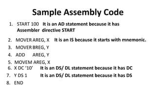
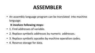
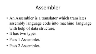
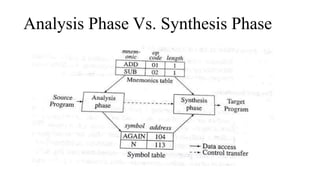
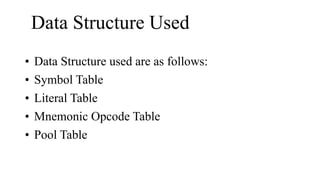
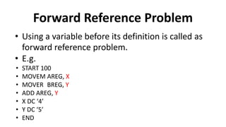
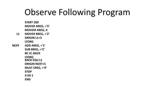
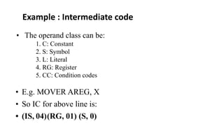
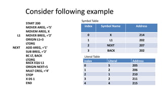
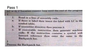
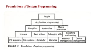
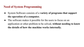
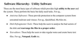
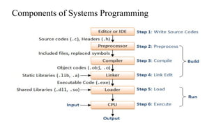
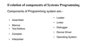
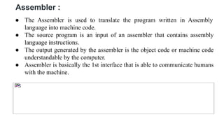
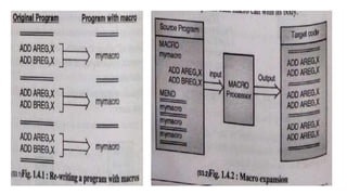
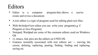
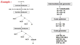
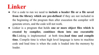
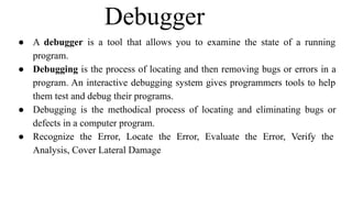
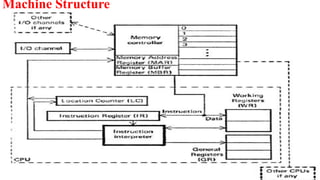
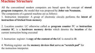
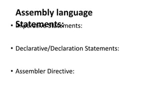
System programming involves developing software like operating systems, compilers, linkers, and device drivers. Key components of systems programming evolution include text editors, assemblers, macros, compilers, interpreters, loaders, linkers, debuggers, and device drivers. Assemblers translate assembly language into machine code. Macros allow frequently used code sequences to be defined once and reused.


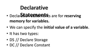
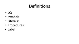
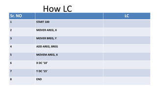
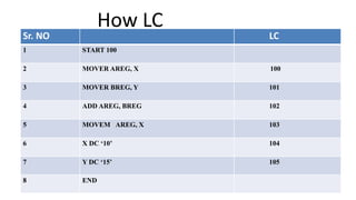
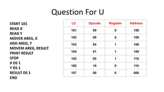
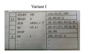
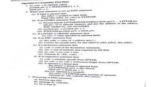
![DS(Declare
Storage):
• Syntax:
• [Label]
• E.g.
DS <Constant specifying size>
X DS 1
DC (Declare Constant):
Syntax:
[Label ]
E.g Y
DC <constant specifying value>
DC ‘5’](https://image.slidesharecdn.com/sposuniti-240124073323-39d2678d/85/SPOS_UNIT-I-System-Programming-and-Operating-System-pdf-69-320.jpg)