Download as PDF, PPTX

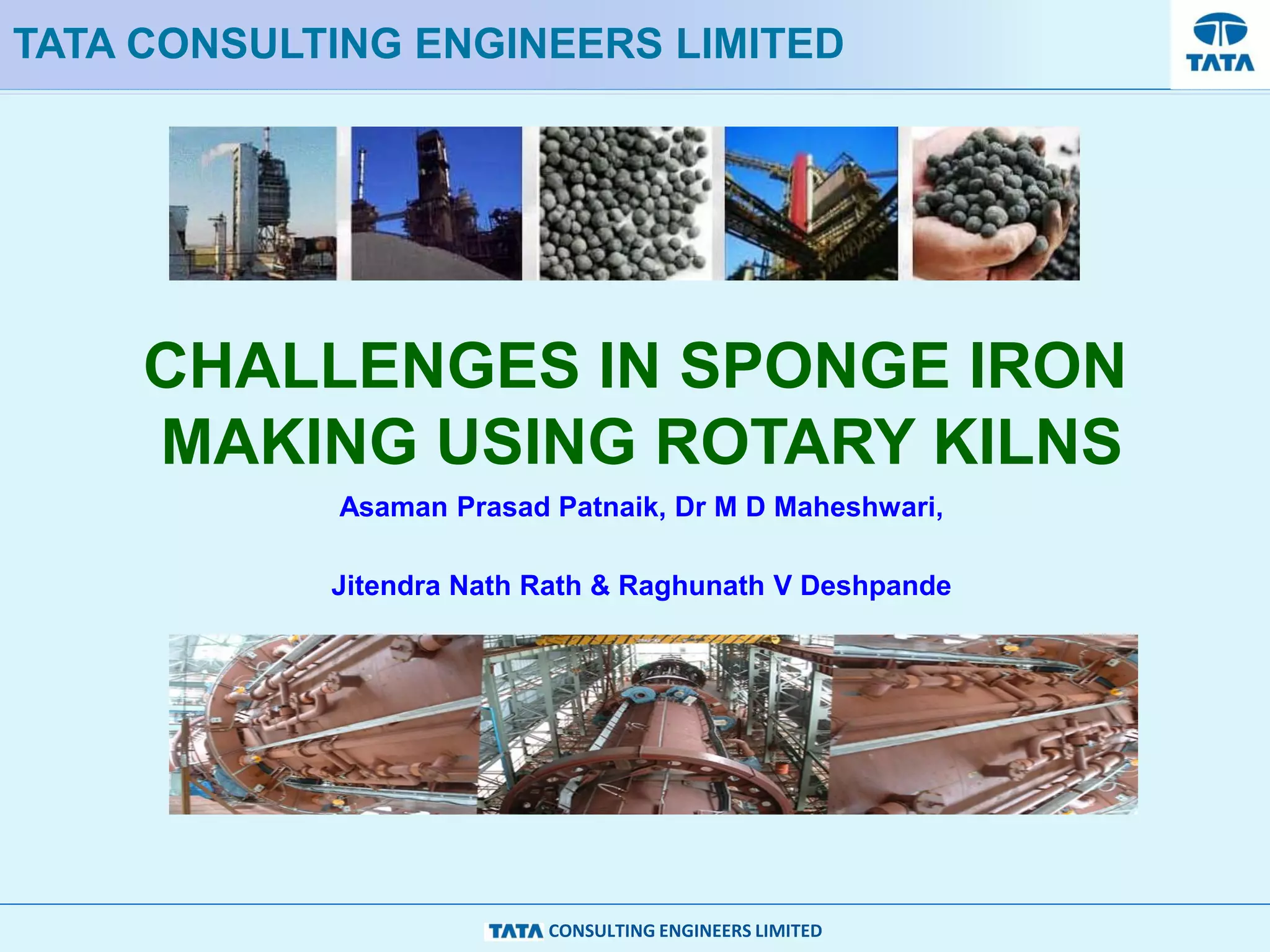
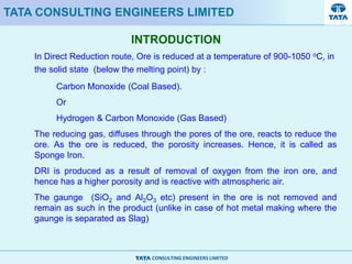
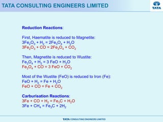
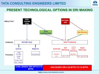
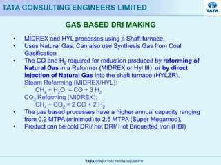
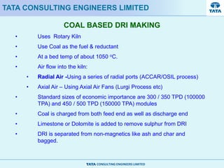
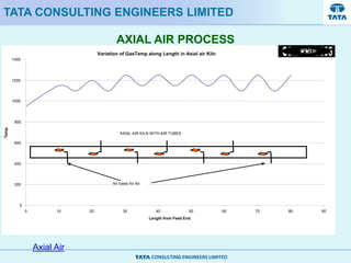
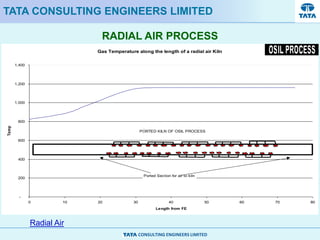
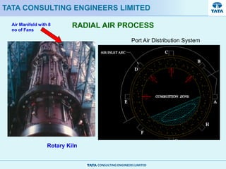
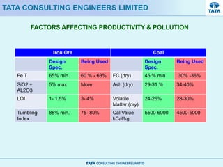
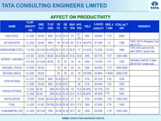
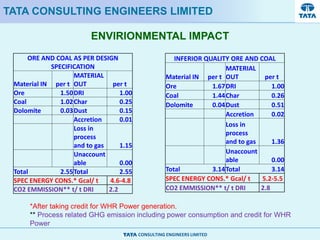
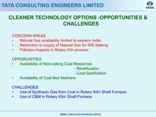
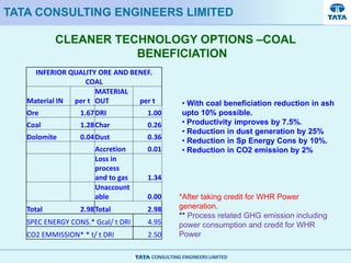
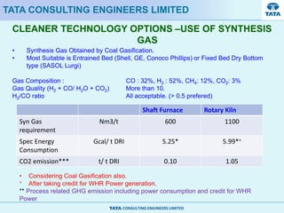
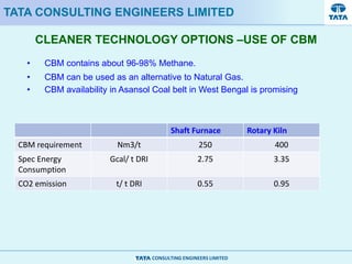
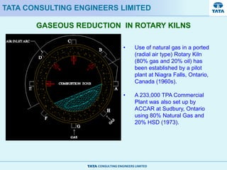
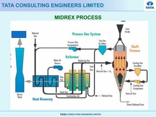
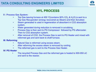
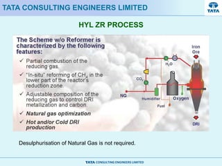
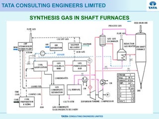

This document discusses challenges in producing sponge iron using rotary kilns. It outlines various technological options for direct reduced iron (DRI) making, including coal-based and gas-based processes. Coal-based DRI uses rotary kilns while gas-based uses shaft furnaces with synthesis gas. Factors affecting productivity and emissions from each process are presented. Opportunities for cleaner technologies like using beneficiated coal or synthesis gas from coal gasification in rotary kilns or shaft furnaces are discussed along with challenges. The MIDREX and HYL gas-based shaft furnace processes and use of synthesis gas in these furnaces are also summarized.


