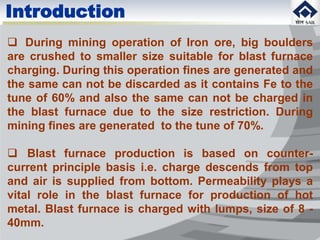
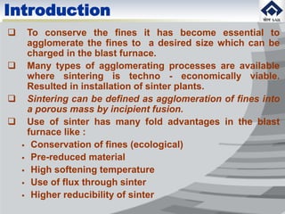
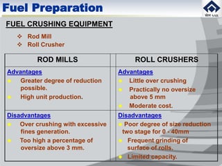
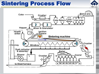
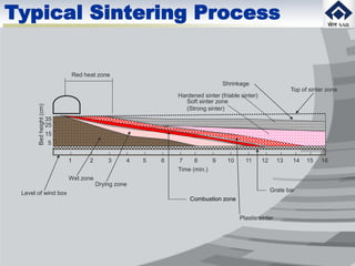
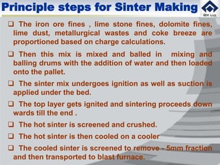
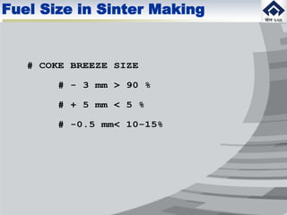
2. Introduction
During mining operation of Iron ore, big boulders
are crushed to smaller size suitable for blast furnace
charging. During this operation fines are generated and
the same can not be discarded as it contains Fe to the
tune of 60% and also the same can not be charged in
the blast furnace due to the size restriction. During
mining fines are generated to the tune of 70%.
Blast furnace production is based on counter-
current principle basis i.e. charge descends from top
and air is supplied from bottom. Permeability plays a
vital role in the blast furnace for production of hot
metal. Blast furnace is charged with lumps, size of 8 -
40mm.
3. Introduction
To conserve the fines it has become essential to
agglomerate the fines to a desired size which can be
charged in the blast furnace.
Many types of agglomerating processes are available
where sintering is techno - economically viable.
Resulted in installation of sinter plants.
Sintering can be defined as agglomeration of fines into
a porous mass by incipient fusion.
Use of sinter has many fold advantages in the blast
furnace like :
Conservation of fines (ecological)
Pre-reduced material
High softening temperature
Use of flux through sinter
Higher reducibility of sinter
4. Raw Material Preparation
Preparation of raw materials and production of consistent
quality sinter is utmost important.
To produce consistent quality sinter maximum attention
is required for preparation of raw materials, and sintering
process.
Why preparation?
To minimize the fluctuation in the quality of final product
What is preparation?
Raw material preparation for sinter making can be
explained as crushing, mixing & granulation of raw
materials with different physico-chemical properties and
proportion of the same (iron ore fines, flux fines, fuel
fines, metallurgical wastes) to provide a homogeneous
mixture, so as to produce sinter which has a good and
consistent metallurgical properties.
5. Raw Material Preparation
Preparation of sinter mix exerts considerable influence on
productivity, quality (RDI,RI), consistency of sinter
chemistry as well as machine operation.
Quality and productivity are determined by coke
combustion behavior during sintering process
Following raw materials are used for sintering:
I/o fines 0 - 10mm (generated )
flux fines 0 - 3mm (crushed)
fuel fines 0 - 3mm ( crushed)
met. wastes 0 - 3mm (generated in plant)
mill scale 0 - 10mm (generated in plant)
6. Raw material preparation for sinter making consists of :
Crushing, Proportioning
Dry mixing
Wet mixing (Balling)
STAGE I:
Crushing of bigger size material to smaller size fraction by hammer
crusher/roll crusher/rod mill for easy and proper mixing.
Fuels and fluxes received in bigger size and can’t be used as such
Combustion behaviour of coke is the controlling factor for sintering
IMPROVEMENT IN COMBUSTION BEHAVIOUR RESULTS IN
Energy saving
Increased productivity
Improved quality of sinter
Raw Material Preparation
7. Flux Preparation
FLUXES :
Limestone
Dolomite
Serpentine (replacement for dolomite)
Calcined lime (absorbs moisture & helps in balling and
preheating of sinter mix)
ADVANTAGES OF ADDING FLUX IN SINTER MIX :
Calcination of flux takes place during sintering process
Intimately mixed with ore and get pre slagged
Sinter produced likely to be more reducible
Increases average permeability which increases rate of
sintering
8. FLUX CRUSHING EQUIPMENT
Primary Crushers
Cone Crusher
Jaw Crusher
Impact breaker
Hammer Mill
Roll Crusher
Secondary Crushers
Rod Mill
Hammer Mill
ENHANCE CRUSHING EFFICIENCY
Hammer Mill to be of reversible type
Hammer to be of flat type preferably of rail steel
Should have variable speed
Flux Preparation
9. FLUX REQUIREMENTS :
Chemical composition
Low in silica & low in alumina
Lower alkali content
Lower sulphur
Proper size grading
Neither too coarse
Nor too fine
FLUX TOO COARSE FLUX TOO FINE
Partial calcination Impairs sinter bed
permeability
Appear preferentially May be drawn out
in return fines – Sinter of bed into the waste
may be weak gas system
Optimum size requirement :
100% (- 3mm) with a minimum of (- 0.25 mm) fraction
Flux Preparation
10. FUELS :
Anthracite
Petroleum coke
Coke breeze (widely employed)
Fuel Preparation
FUEL REQUIREMENTS :
Lower content of volatiles
Adequate fuel reactivity
Proper size grading
Low moisture content
High volatile content leads to :
Volatiles distill out of bed in advance of flame front –
calorific value of fuel is wasted
Condenses oily liquids in wind legs & mains causing
practical difficulties.
11. Fuel Preparation
High reactive Low reactive
Lower thermal efficiency low max. Temp.
Higher CO conc. in widening of comb.
waste gas zone
Too coarse Too fine
Segregation problem decrease efficiency
Localized hot spots decrease permeability
Broaden combustion zone premature combustion
Over wet fuel :
Difficult to extract at uniform rate
Difficult to disperse uniformly
Crushing efficiency comes down
Optimum size requirement :
100% (-3mm) with a minimum of –0.25mm
12. ROD MILLS ROLL CRUSHERS
Advantages
Greater degree of reduction
possible.
High unit production.
Advantages
Little over crushing
Practically no oversize
above 5 mm
Moderate cost.
Disadvantages
Over crushing with excessive
fines generation.
Too high a percentage of
oversize above 3 mm.
Disadvantages
Poor degree of size reduction
two stage for 0 - 40mm
Frequent grinding of
surface of rolls.
Limited capacity.
FUEL CRUSHING EQUIPMENT
Rod Mill
Roll Crusher
Fuel Preparation
13. Dry Mixing
STAGE II :
DRY MIXING:
Proportioned raw materials are mixed in a mixer for homogenization
of sinter mix
Two types of mixers are available:
Drum type mixers are for high capacity (lifters are provided)
High intensity mixer
PARAMETERS OF DRUM
Speed and inclination angle of drum is adjusted to achieve
residence time of 1 – 3 minutes
20% degree of filling of total volume of the drum
Generally the drum length is three times higher than it’s diameter
IMPROVEMENT IN MIXING EFFICIENCY OF MIXER BY
Increase in mixing time
Optimisation of speed and angle of the drum
Increase the length of the drum
14. Advantages of using High
intensity mixer:
Mixing and homogenization of
sinter mix to the level achieved in
a base mix yard
Ultra fines can be used in sinter
mix
BOF sludge can also be used
effectively in the sinter mix
Size reduction of over sized
material in the mix due to
agitation effect
High Intensity Mixer
15. Wet Mixing (Balling)
STAGE III :
WET MIXING
Sinter mix after mixer is charged in a Pelletising/Granulating Drum
Green ball formation:
Drum rotates slowly : Charge does not roll but slides as mass in swinging
movement upwards and downwards on the wall -- No agglomerates formed
Drum rotates in a speed such that due to the frictional resistance prevailing
on the wall, the charge is lifted untill the material reaches and exceeds
dynamic angle of repose on the charge surface where the friction reaches
its minimum the particle begins to roll down - Cascade Movement -
Agglomerates formed
Drum rotates so fast : The charge is moved beyond the dynamic angle of
repose and pressed against the wall - No agglomerates formed
GRANULATION OF SINTER MIX IS INTENSIFIED BY FOLLOWING :
Maintaining cascading regime by appropriate selection of rotational
speed
Degree of filling of charge in the range of 6 - 8%
Optimum moisture in the initial zone to 1/3 length of the drum
16. During sintering preheating of sinter mix, combustion of fuel,
decomposition of carbonates, oxidation and reduction of oxides
and formation of sinter takes place in small portion of the height
of bed.
The reaction zone is shifted continuously towards the grate by
method of suction. The heating of sinter mix at each elementary
layer takes place both due to heat transfer from layers lying
above (mainly by convection) and due to the heat generated
during combustion of fuel. The heat accumulated in this layer is
spent in preheating and melting of particles of sinter mix and
also in occurrence of endothermic reaction (decomposition of
hydrates and carbonates).
After completion of combustion of coke and formation of sinter,
cooling of sinter starts. The heat is transferred to air passing
through and also partly (by radiation and thermal conduction) to
sinter layer below.
Sintering Process
17. After ignition, hot products of combustion of gases are
sucked through bed and transfer their heat to a very narrow
layer of sinter mix at the top removing moisture from this layer
and creating conditions for the beginning of combustion of
coke particles in the mix
Important feature of sintering is, each moment coke particles
present in a narrow layer 30 to 40 mm burns out
All coke particles located below are not heated to a
temperature (700oC) or don’t get sufficient 02 from above.
combustion zone moves down wards through whole bed only
after the carbon is burn out in each layer
At any given moment, zone of ready sinter is there above the
zone of combustion and air passes through this zone. Sinter
gets cooled by the air which gets pre heated and this heat is
utilised in the combustion zone
Combustion product coming out of combustion zone give up
their heat to small layer of cold mix which gets heated quickly.
Temperature of waste gas at exhauster is 600C for long time
and for few minutes of the process raises to 3000C. The
temperature at combustion zone reaches 14000C
Sintering Process
18. Raw mix adjacent to combustion zone is pre heated quickly
and loses hygroscopic moisture and then hydrate moisture.
Water vapours condense on layers of cold mix and create
zone of re-condensation of moisture and exceeds more than
initial moisture
In pre heating zone chemical reaction between solid phases
takes place, carbonates & hydrates decompose
Sintering of iron ore fines by suction is defined by the heat
transfer between gas and solids. The evaluation, movement
and assimilation of heat occurring due to passage of air
thro. Bed determines the temp. level of heating of solids and
cooling of sinter and also the rate of sintering
The temperature level to a considerable extent determines
the strength of sinter
Sintering Process
20. 1 2 3 4 5 6 7 8 9 10 11 12 13 14 15 16
Red heat zone
Top of sinter zone
Shrinkage
Soft sinter zone
(Strong sinter)
Hardened sinter (friable sinter)
Bedheight(cm)
5
15
25
35
Level of wind box
Grate bar
Combustion zone
Drying zone
Wet zone
Time (min.)
Plastic sinter
Typical Sintering Process
21. Cooling of Sinter
TASKS TO BE PERFORMED BY COOLER
COOL SINTER TO LESS THAN 1000C
MINIMUM LEVEL OF POWER CONSUMPTION
MINIMUM OPERATING COST
FACILITY FOR RECOVERY OF HEAT
ENVIRONMENT FRIENDLY
22. ON STRAND COOLING
PAN COOLER
STRAIGHT LINE COOLER
CIRCULAR COOLER
Types of Cooler
23. Principle steps for Sinter Making
The iron ore fines , lime stone fines, dolomite fines,
lime dust, metallurgical wastes and coke breeze are
proportioned based on charge calculations.
Then this mix is mixed and balled in mixing and
balling drums with the addition of water and then loaded
onto the pallet.
The sinter mix undergoes ignition as well as suction is
applied under the bed.
The top layer gets ignited and sintering proceeds down
wards till the end .
The hot sinter is screened and crushed.
The hot sinter is then cooled on a cooler
The cooled sinter is screened to remove - 5mm fraction
and then transported to blast furnace.
26. ROLL OF RETURN SINTER
# RETURN SINTER IS A NECESSARY EVIL
# HELPS IN SINTER MIX PERMEABILITY
# REDUCES SINTER YIELD
# REDUCES PRODUCTIVITY
Roll of return Sinter
27. SIZE OF RETURN SINTER
# UNDER INDIAN CONDITIONS RETURN SINTER SIZE IS
<5 mm WITH +5 mm < 5%
# JAPANESE USE -3 mm AND AT TIMES USE
-1 mm WITH PREFERENTIAL CHARGING IN BF.
Return Sinter Size
29. RETURN SINTER BALANCE
TOTAL RETURN SINTER ADDED = TOTAL RETURN
SINTER GENRATED
TOTAL RETURN SINTER CHARGED IN SINTER
MIX(t/hr) = IN-PLANT RETURN SINTER (t/hr)
+ BF RETURNS (t/hr)
Return Sinter Balance
30. RETURN SINTER BALANCE
RETURN SINTER BALANCE CAN BE ACHIEVED BY:
1) CONSISTANCY IN RAW MATERIAL GRANULOMETRY AND
CHEMISTRY
2) CONSISTANCY IN OPERATION
3) CONTINUOUS RUNNING OF MACHINE
Return Sinter Balance
34. REDUCTION IN RETURN SINTER
GENERATION
1) RAW MATERIALS
2) PROCESS
3) TRANSPORTATION
Reduction in Return Sinter
35. SOURCES OF RETURN SINTER GENERATION
RAWMATERIALS:
# PRESENCE OF +5 mm IN I/O FINES
# PHASE 1: TOTALLY ELIMINATE +10mm
# PHASE 2: REDUCING +8 mm TO < 5%
# PHASE 3: REDUCING +5 mm TO < 5%
# PRESENCE OF +5 mm IN RETURN SINTER
Source of Return Sinter
46. PROCESS:
WATER ADDITION ON HOT SINTER
WATER
ADDITION ON
HOT
SINTER
THERMAL SHOCK
CRACKS
FORMATION
MORE RETURN
SINTER
GNERATION
Process Improvement
47. BF RETURNS
# BF RETURN SINTER SIZE
#SIZE SHOULD BE -5mm WITH +5mm<5%
Transportation
48. BF RETURNS
CAUSES OF BF RETURN SINETR
GENERATION:
# DEGRADATION OF SINTER DURING
TRANSPORTATION
# NON-OPTIMUM HIGH LINE BUNKER LEVEL.
# LOWER SCREENING EFFICIENCY OF BF
SCREENS.
Causes for BF return
49. BF RETURN SINTER GENERATION COULD BE
REDUCED
BY:
# REDUCING DEGRADATION AT TRANSFER POINTS BY
INSTALLING STONE BOXES OR LADDER TYPE
CHUTES.
# MAINTAINING THE HIGH LINE BUNKER LEVEL AT
40-50%
# IMPROVING THE SCREENING EFFICIENCY OF BF
SINTER SCREENS
# RE-SCREENING OF BF RETURN SINTER
Measures to be taken
50. MEASURES ADOPTED ABROAD TO REDUCE RETURN
SINTER GENERATION(PHILIPPINES SINTER CORPN,
KAWASAKI AND KAHASAKI STEEL, JAPAN)
# PRODUCTION OF HARD SINTER , S.I>90%
# IMPROVED SINTER SCREEN EFFICIENCY TO GET
-5mm%<3%
# MINIMIZING DROP HEIGHT BY SIMPLIFYING
LAYOUTS AND ADOPTING SMALLER SIZE HEAD
PULLEYS AT EACH BELT CONVEYOR
# ADOPTION OF LADDER AND SELF LINING TYPE
CONVEYOR CHUTES
# CONTROLLING BIN LEVEL OF BF.
Measures adopted in Abroad
55. RDCIS Innovation
Low moisture sintering operation by
introduction of magnetic water in balling
drum
Preheating of sinter mix by steam in the
surge hopper of sinter machine
Introduction of air humidification
system
Introduction of magnetic plate charging
system
56. Low moisture sintering operation
SCHEMATIC DIAGRAM OF MAGNETIC WATER CONDITIONER LOCATION
Magnetic water
conditioner
SMDWater line
Shuttle
Conveyer
Sinter mix
Conveyer
Intermediate
bunker
Segregation Plate Drum Feeder
Pallet
57. Results
Reduction in moisture content of sinter mix through
magnetic treatment of water has resulted in lowering of
thermal requirement at Sinter Plant # 2 & 3 of Bhilai Steel
Plant
Results:
Sp. Coke Breeze Consumption : 5 Kg/t & 1.6 Kg/t
(SP- 2 & SP-3, BSP)
- 5 mm sinter fraction at BF skip : 4% & 2 % (abs.)
(SP- 2 & SP-3, BSP)
58. Pre heating of sinter mix above dew point
suppress the re-condensation phenomena in
the lower portion of sinter bed
Different methods of pre heating of sinter mix
are in practice. Some of them are:
Use of hot return sinter
Use of hot water
Use of gaseous fuel
Steam injection
Preheating of sinter mix
59. Various Preheating system
Plant Increase in
Temp.
Preheating
system
Improvement
Krivorg
(USSR)
330C – 580C Steam heating
in balling drum
5-7% ↑ in productivity,
2-3% ↓ in fines content
Komm-
unarsk
(USSR)
200C – 580C Steam heating
in balling drum
5% ↑ in productivity for
each 100C rise in
temperature
Chere-
povets
(USSR)
160C – 540C Steam heating
in balling drum
11.4% ↑ in productivity,
4% ↓ in Specific coke
consumption
Makee-
viers
France
350C – 720C Steam heating
in balling drum
16% ↑ in productivity,
6 Kg/t ↓ in Specific
coke consumption
Fukuy-
ama
(Japan)
300C – 450C Steam heating
in balling drum
7% ↑ in productivity,
60. Actuator type
shut off valve
Glove
valve PI TI
Surge Hopper
Flange
Drum Feeder
Steam Header (80NB)
Sloping
Chute
Pallet
By injecting steam in the surge hopper to raise the temperature
of sinter mix from 250C to 650C to suppress the re-condensation
of moisture in the lower part of the sinter bed.
Preheating of sinter mix
61. Results
Increase in :
Sinter Machine speed by 5%
Sinter Plant Productivity by 17%
Decrease in :
- 5mm skip sinter by 20 - 30%
Sp. coke consumption by 5%
PARAMETERS BASE PERIOD TRIAL PERIOD
Specific Coke Breeze (Kg/t) 68 63
- 5 mm content in BF – 6 (%) 7.6 5.8
- 5 mm content in BF – 7 (%) 7.0 5.2
Sp. Productivity (t/m2/hr) 1.29 1.438
Sinter Plant # 2, BSP
62. Air Humidification System
The productivity of sinter plants is constrained by high FeO (8-10%) sintering
operation which restricts the sinter machine speed due to high resistance (at
combustion zone) to air flow in the latter half of sinter machine. Air
humidification is aimed to reduce the thickness of the high temperature
(>6000C) zone. The intensification of sinter process occurs due to
humidification is as follows :
Oxygen enrichment of air
Improvement of heat transfer process
Acceleration of CO combustion reaction in presence of water vapour
BedHeight,mm
Feed End Length of Sinter M/c Discharge End
20
%
80
%
Sinter Zone
High Temp. ZoneGreen Sinter Mix Zone
Sinter Zone
High Temp. ZoneGreen Sinter Mix Zone
60
%
40
%
Feed End Length of Sinter M/c Discharge End
BedHeight,mm
Present Status
After Innovation
64. magnetic plate creates
magnetic field, which
creates a magnetic force on
the sintering materials
during dropping.
This magnetic forces
increases frictional
resistance of the material
by an amount µ×FM
This creates a braking
effect on the materials and
void fraction during
charging increases.
Magnetic Plate Charging System
65. Schematic diagram of the magnetic
charging system
Raw mix charging hopper
Drum
feeder
Sinter pallet travel
SS 304 plate &
Polyurethane
liners
Mother plate
Magnets in charging chute
v
v
Magnets
Return sinter
& Mill Scale
Magnetic Plate Charging System
66. Low MgO Sintering at BSL
Single Balling Drum & Low MgO Operation
at Sinter Plant, BSL
Work Done :
Single balling drum operation for better homogenization of
sinter mix in Sinter Band No. # 2
Decrease in MgO content of sinter, by increasing
Limestone/dolomite ratio in flux bed
Results :
Sinter Band No. # 2 MgO
(%)
Quality of Sinter
Fe in
sinter (%)
DTI
(+6.3mm) %
(- 5) mm % in
Skip Sinter
Before Experiment 4.2 52.1 70.1 13.4
During Experiment 3.8 53.6 70.6 10.0
By lowering MgO from 4.2 to 3.8 %, Fe in sinter increases
from 52.1 to 53.6 %
(- 5) mm % in skip sinter decreased from 13.4 to 10.0 %