Download to read offline
![George J Ferko V 1
The Effect of Ytterbium on the Grain Growth of Magnesium Aluminate Spinel
George J. Ferko V 1
12/10/2011
Abstract
Pressureless sintering of undoped magnesium aluminate spinel and spinel doped with 500
ppm of ytterbium has been investigated. It has been found that the addition of ytterbium at this
level causes an increase in grain growth and a decrease in abnormal grain growth. The
cumulative distribution functions of the grain size data have been evaluated using probability
plots and it has been found that the data fits a gamma distribution function much better than a
log- normal distribution function. This probability analysis allows for the grain size data to be
observed in a much more meaningful way then has been previously reported for this system. It
has also been found that the bi-modal, or duplex microstructure, often observed in spinel occurs
in undoped samples, thus it cannot be attributed to the presence of a specific dopant at this time.
Introduction
Polycrystalline magnesium aluminate spinel (spinel) has been found to have attractive
properties for the production of transparent armor and radar and detector domes and windows.
The recent availability of high purity spinel powders has brought spinel to the forefront of
transparent armor, window, and dome design by allowing for spinel to be manufactured with
high transparency in the midwave infrared (MWIR) range and the ultraviolet-visible (UV-VIS)
range[1-8]. Spinel has consistently exhibited high fracture toughness and hardness as well [9-
17]. When we combine these properties with the relatively low density of spinel compared to
other popular transparent armor materials such as AlON or sapphire the study of spinel becomes
an even more attractive venture [18].
Research on the spinel system over the last 50 years has focused on the study of sintering
additives, or dopants, and their ability to produce economical and consistent commercial spinel
[8]. Despite a large body of work precise control over the microstructure of spinel has yet to be
realized. Spinel continues to exhibit a common duplex microstructure where large grains seem
to be imbedded in a matrix of much smaller grains, a feature that has been attributed to the use of
LiF as a sintering additive [19]. This is particularly troubling in the spinel system as its
transparency depends on the porosity of the final product and the mechanical properties of spinel
are highly dependent on average grain size and grain size distribution. In order to improve spinel
so that it may reach its full potential it is necessary to analyze the sintering kinetics of spinel in
relation to certain model additives or dopants. The analysis of the sintering kinetics of doped
spinel should be done in conjunction with observation of the grain boundaries using high-angle
annular dark field scanning transmission electron microscopy (HAADF STEM) and high-
resolution STEM so that the structure at the grain boundary, or the grain boundary complexion,
can be related to the sintering kinetics. Rare earth dopants such as La, Dy, Eu, and Yb have
recently been found to be easily observable at the grain boundaries of spinel using HAADF
STEM by Perkins, et al. [20-22]. The drastically different atomic number of these dopants from
the molecular constituents of spinel makes the z-contrast produced by HAADF STEM
exceptional.
1
Graduate Student – Lehigh University
Email: george.ferko.v@gmail.com
Phone: 610.597.8007](https://image.slidesharecdn.com/0a2316cd-e704-4de0-9f5d-a5a44bf5f694-161002072737/85/Spinel-Yb-grain-growth-and-prob-analysis-1-320.jpg)
![George J Ferko V 1
The Effect of Ytterbium on the Grain Growth of Magnesium Aluminate Spinel
George J. Ferko V 1
12/10/2011
Abstract
Pressureless sintering of undoped magnesium aluminate spinel and spinel doped with 500
ppm of ytterbium has been investigated. It has been found that the addition of ytterbium at this
level causes an increase in grain growth and a decrease in abnormal grain growth. The
cumulative distribution functions of the grain size data have been evaluated using probability
plots and it has been found that the data fits a gamma distribution function much better than a
log- normal distribution function. This probability analysis allows for the grain size data to be
observed in a much more meaningful way then has been previously reported for this system. It
has also been found that the bi-modal, or duplex microstructure, often observed in spinel occurs
in undoped samples, thus it cannot be attributed to the presence of a specific dopant at this time.
Introduction
Polycrystalline magnesium aluminate spinel (spinel) has been found to have attractive
properties for the production of transparent armor and radar and detector domes and windows.
The recent availability of high purity spinel powders has brought spinel to the forefront of
transparent armor, window, and dome design by allowing for spinel to be manufactured with
high transparency in the midwave infrared (MWIR) range and the ultraviolet-visible (UV-VIS)
range[1-8]. Spinel has consistently exhibited high fracture toughness and hardness as well [9-
17]. When we combine these properties with the relatively low density of spinel compared to
other popular transparent armor materials such as AlON or sapphire the study of spinel becomes
an even more attractive venture [18].
Research on the spinel system over the last 50 years has focused on the study of sintering
additives, or dopants, and their ability to produce economical and consistent commercial spinel
[8]. Despite a large body of work precise control over the microstructure of spinel has yet to be
realized. Spinel continues to exhibit a common duplex microstructure where large grains seem
to be imbedded in a matrix of much smaller grains, a feature that has been attributed to the use of
LiF as a sintering additive [19]. This is particularly troubling in the spinel system as its
transparency depends on the porosity of the final product and the mechanical properties of spinel
are highly dependent on average grain size and grain size distribution. In order to improve spinel
so that it may reach its full potential it is necessary to analyze the sintering kinetics of spinel in
relation to certain model additives or dopants. The analysis of the sintering kinetics of doped
spinel should be done in conjunction with observation of the grain boundaries using high-angle
annular dark field scanning transmission electron microscopy (HAADF STEM) and high-
resolution STEM so that the structure at the grain boundary, or the grain boundary complexion,
can be related to the sintering kinetics. Rare earth dopants such as La, Dy, Eu, and Yb have
recently been found to be easily observable at the grain boundaries of spinel using HAADF
STEM by Perkins, et al. [20-22]. The drastically different atomic number of these dopants from
the molecular constituents of spinel makes the z-contrast produced by HAADF STEM
exceptional.
1
Graduate Student – Lehigh University
Email: george.ferko.v@gmail.com
Phone: 610.597.8007](https://image.slidesharecdn.com/0a2316cd-e704-4de0-9f5d-a5a44bf5f694-161002072737/75/Spinel-Yb-grain-growth-and-prob-analysis-1-2048.jpg)
![George J Ferko V 2
Recently published data by Benamuer, et al. has shown a systematic evaluation of the
sintering kinetics of spinel using pressureless sintering and a commercially available high purity
spinel powder [23]. The experiment described in this report will, in many ways, be modeled
after the work done by Benamuer except a Yb dopant will also be used so that the grain
boundary structure can be observed at a later point. The goal of this experiment is to establish
the effect that Yb doping has on the grain growth and the grain size distribution of spinel as an
initial step to further understanding the microstructural development of spinel.
Experimental Methods
A commercially available high purity spinel powder (S30CR, Baikowski, Annecy,
France) was used as the starting powder. The impurity data for this powder, seen in table 1, is
available from the supplier and agrees well with the inductively coupled plasma spectroscopy
performed by Benamuer [23]. A Yb dopant
precursor in the form of high purity ytterbium
nitrate hydrate was obtained from (Alfa Aesar,
Ward Hill, MA). Ytterbium nitrate hydrate readily
dissolves in most solvents making it easier to
homogeneously distribute the dopant in the powder.
The dopant precursor is dissolved in 200 proof
ethanol and the powder is combined with the dopant
in ethanol to produce a doping level of 500ppm Yb.
The powder and dopant are mixed in a PFA jar
using a magnetic stirring rod under vacuum at a
temperature of 80o
C to facilitate the evaporation of the ethanol. This mixing method was used to
preserve the stoichiometry and purity of the powder. All of the labware used is cleaned using
aqua regia and hydrogen peroxide to remove any potential contaminants.
Both the doped and undoped powders are formed into pellets by uniaxially pressing the
powders in a high density polyethylene die and punch arrangement at 35 MPa. A large sample
size is chosen, 1” diameter by ¾” height, because Mg evaporation has been observed at the
surfaces of spinel samples when they are sintered in a reducing atmosphere [19]. The density of
the green pellets at this stage was not measured to prevent contamination and because the pellets
are very fragile at this stage. The pellets are cold isostatically pressed at 275 MPa for 2 minutes
giving them a green density of about 45%. The pellets are then packed in powder of the same
composition inside high purity alumina crucibles in a double crucible arrangement in preparation
for sintering. The sintering is performed in a high temperature graphite furnace (Thermal
Technologies, Santa Rosa, CA) in a 5% hydrogen 95% nitrogen reducing atmosphere. The
samples are first raised to 800o
C for 1 hour in a calcining step to remove the nitrates, water, and
hydrocarbons from the samples. The Yb precursor has been found to convert entirely into Yb2O3
at 550o
C so the calcining temperature and time should successfully remove the impurities from
the sample [24]. The furnace temperature is then raised to 1800o
C and held for dwell times of 1,
2, and 4 hours.
The large pellets were sectioned so that a 5mm by 5mm by 5mm square was removed
from the center of the pellet. The sample was then ground and polished in preparation for
EBSD. In order to ensure that there was little surface damage from the grinding a minimal force
of 4 MPa was used for all grinding and polishing steps and after each step the sample heights
Table 1: Impurity data for the S30CR
powder from Baikowski [23].
Baikowski S30CR Powder Purity
S (ppm) 800-900
K(ppm) 40
Na(ppm) 11
Fe(ppm) <10
Ca(ppm) <10
Si(ppm) <10](https://image.slidesharecdn.com/0a2316cd-e704-4de0-9f5d-a5a44bf5f694-161002072737/85/Spinel-Yb-grain-growth-and-prob-analysis-2-320.jpg)
![George J Ferko V 3
were measured to ensure that four times the particle size of the previous grinding medium had
been removed to minimize the surface damage in the sample.
In preparation for EBSD the samples were given a 4nm coating of Ir to prevent charging
effects. EBSD patterns were obtained in a Hitachi 4300 Cold Field Emission High Resolution
Scanning Electron Microscope equipped with an EBSD detector using the EDAX TSL/OIM data
collection and analysis software. Each sample was scanned 10 to 15 times in order to obtain at
least 1000 grains per sample. Scans were done at varying magnifications and step sizes to ensure
that very small grains or very large grains were not absent in the scans of each sample. The
EBSD data for this experiment is meant to be used to automatically determine the grain size
distribution. The grain size distribution provides us with a lot more information than just the
average grain size and can be helpful in evaluating the abnormal grain growth in our samples.
The raw data cannot simply be measured for grain size, it must first be cleaned using
grain dilation and partitioned to eliminate grains that are only made up of a few pixels and are
either false readings from pores or are grains that are too small to be mapped with the EBSD step
sizes used. Then the data is overlaid onto the SEM signal to make sure the microstructure
produced is representative of what is actually there. Next the edge grains are subtracted out and
this data is used to form the grain size distributions. A schematic of the data processing is shown
in figure 1. By varying the step size and magnification any large grains excluded because they
were on the edge of the frame should be accounted for by other scans.
Figure 1: Schematic of the data processing used to go from the raw EBSD data to the data used
for the analysis of the grain size distribution.
The grain size data is binned to produce histograms of the grain size distributions;
however, in order to properly analyze the data it must be evaluated as a cumulative distribution
function and then plotted on a probability plot to see how well the data fits a distribution
function. The most common distribution function used is the log-normal distribution function
[25-27]; however, it has been found that some data fits the gamma distribution much better [28]
so both distributions are used in the statistical analysis. The distributions are used because they
are multiplicative like grain growth and the two distributions are actually quite similar. The](https://image.slidesharecdn.com/0a2316cd-e704-4de0-9f5d-a5a44bf5f694-161002072737/85/Spinel-Yb-grain-growth-and-prob-analysis-3-320.jpg)
![George J Ferko V 5
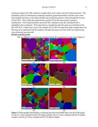
The scale of the micrographs is not the same between different sintering times; however, the
scale is the same between the doped and undoped samples for each time. In figure 2a there are at
least two different kinds of grains present in what could be called a duplex microstructure. It
should be noted that these sorts of grain size distributions in spinel are often attributed to Li and
F ions, due to the common use of LiF as a dopant in spinel, causing an inhomogeneous
coarsening effect [19]; however, no LiF is present in this sample which makes this result
somewhat significant and might mean that the inhomogeneous coarsening or abnormal grains are
due to the other impurities found in the starting powders. Throughout the undoped sample very
large grains from 20 to 70um in diameter are observed as well as grains that range from 1 to 5
um in diameter. These large grains might be considered abnormal grains and the analysis of the
grain size distributions, to be discussed later, will help to identify whether or not the grains are
growing abnormally. There is a clear difference in grain size between the doped and undoped
samples even at 1 hour of annealing time. The micrographs in figure 2a and 2b show clearly that
even at a one hour dwell time the Yb-doped grains have grown to be much larger than those of
the undoped grains. The histograms of the grain size distributions for all of the samples are
shown in figure 3.
(a) (b)
(c) (d)
(e) (f)
Grain Size (µm) →
Figure 3: Plots of the grain size histograms for the (a) undoped 1 hour and (b) Yb doped
samples, the (c) 2 hour undoped and (d) Yb doped samples, and the (e) 4 hour undoped and (f)
Yb doped samples.
In figure 3b and 3a it can be seen that the grain size distribution for the doped grains in the 1
hour sample is much broader than that of the undoped grains. In the doped one hour sample we
have a range of grain sizes from 5-60um where it is not clear if any of the grains are growing
abnormally. This is in contrast with the undoped one hour sample where the distribution is very
sharp so that any grains outside of the distribution are easy to spot.
Frequency→](https://image.slidesharecdn.com/0a2316cd-e704-4de0-9f5d-a5a44bf5f694-161002072737/85/Spinel-Yb-grain-growth-and-prob-analysis-5-320.jpg)
![George J Ferko V 6
In the two hour samples in figure 2c and d and figure 3c and d the grain size distributions
have broadened significantly as well as having increased in grain size. The broadening of the
undoped sample grain size distribution may be occurring because the abnormal grains are
becoming impinged and beginning to slow down while the normal grains continue to coarsen.
The 4 hour samples in figure 2e and f and figure 3e and f exhibit grain size distributions very
similar to those of the 2 hour samples. Significant broadening of the grain size distrtributions is
not discernable, however, as would be expected the grains have continued to grow in what
appears to be pure coarsening.
An attempt was made to quantify the pore size distribution by binarizing the SEM signal
from the EBSD scans, however, because the magnifications used were meant to capture the
range of grain sizes and not that of the pore sizes the data comes out nonsensical so the pore size
data that was obtained will not be included in this report as it cannot be quantified properly. This
also makes it impossible to fit any sort of microstructural development models for porous
compacts to the grain growth and densification data. It should be noted, however, that using
similar methods Benamuer, et al., were able to produce nearly fully dense samples in the range
of sintering times used here [23]. This difference may be due to the large sample size used here.
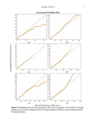
In figure 4 we see a plot of the log average grain size versus log time which shows that
the grain size of the Yb-doped grains is consistently higher than that of the undoped grains. This
shows that the Yb dopant is producing an increase in mobility that allows the spinel grains to
grow at a faster rate.
Figure 4: Plot of the log average grain size versus the log time for all of the samples produced.
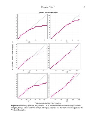
As stated earlier the average grain size and the histograms do not show enough
information to convincingly say whether or not grains are growing abnormally so cumulative
distribution functions were applied to the grain size data and probability plots were produced to
determine which CDF the grain size data fits best and which grains deviate significantly from
that distribution function. The plots of the CDFs, i.e. cumulative percent versus CDF, are not
included here to save space. In figure 5 the probability plots for the log-normal distributions for
all of the samples are shown. The plot for each sample is shown individually because the large
number of data points from each sample becomes very confusing on a consolidated plot. Also,
500 ppm Yb-
doped
Undoped
0
0.2
0.4
0.6
0.8
1
1.2
1.4
1.6
1.8
2
3.5 3.6 3.7 3.8 3.9 4 4.1 4.2
log(Ḡ)(µm)
log(t) (s)](https://image.slidesharecdn.com/0a2316cd-e704-4de0-9f5d-a5a44bf5f694-161002072737/85/Spinel-Yb-grain-growth-and-prob-analysis-6-320.jpg)

The document summarizes an experiment that investigated the effect of ytterbium doping on the grain growth of magnesium aluminate spinel. It was found that doping with 500 ppm of ytterbium caused an increase in grain growth and a decrease in abnormal grain growth compared to undoped samples. Electron backscatter diffraction and microscopy were used to analyze the grain size distributions of doped and undoped samples sintered for 1, 2, and 4 hours. Probability analysis showed that the grain size data fit a gamma distribution better than a log-normal distribution. Ytterbium doping resulted in consistently larger grain sizes compared to undoped samples.


