Download to read offline


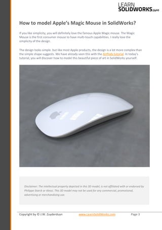
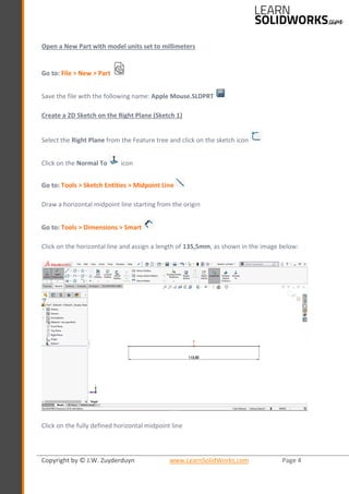
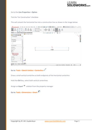
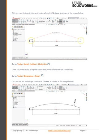

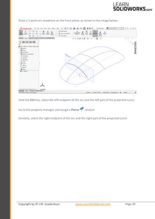
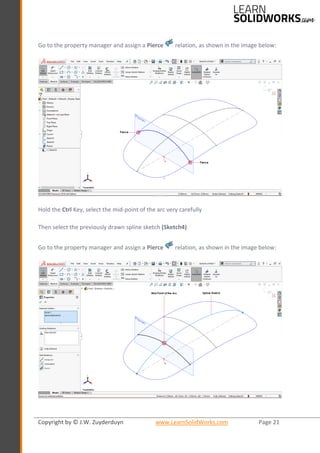
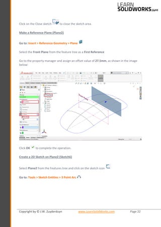
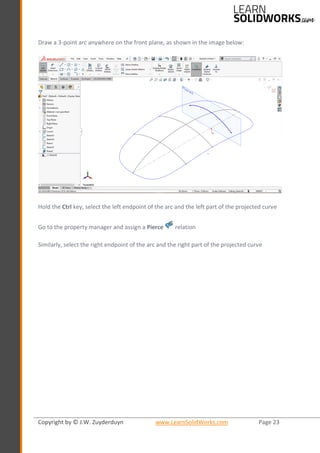
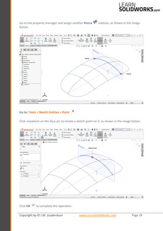
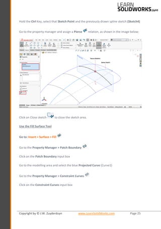
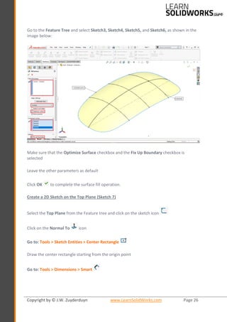
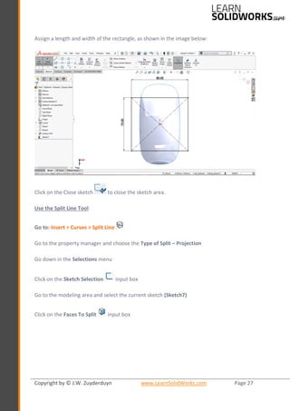
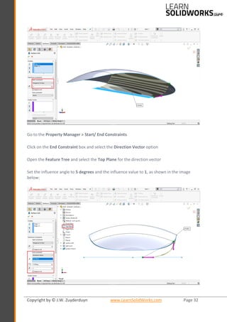
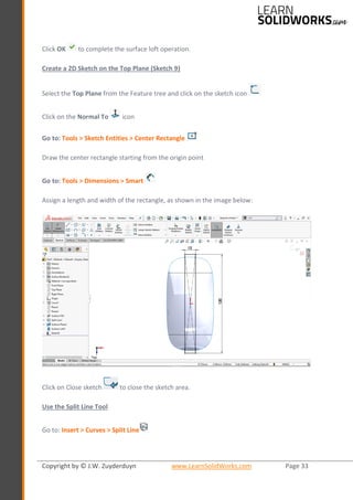
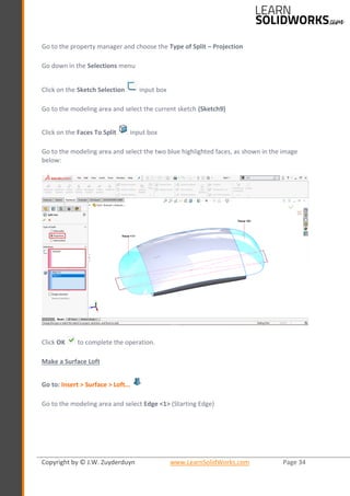
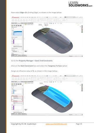


- The document describes how to model Apple's Magic Mouse in SolidWorks. It provides step-by-step instructions to create 2D sketches on different planes and reference geometry to model the shape of the mouse. 5 sketches are made on different planes and surfaces to construct curves and arcs representing the silhouette of the mouse. Dimensioning and geometric relations are applied to fully define the sketches.