Download to read offline
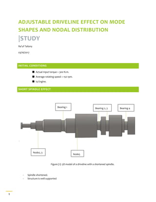
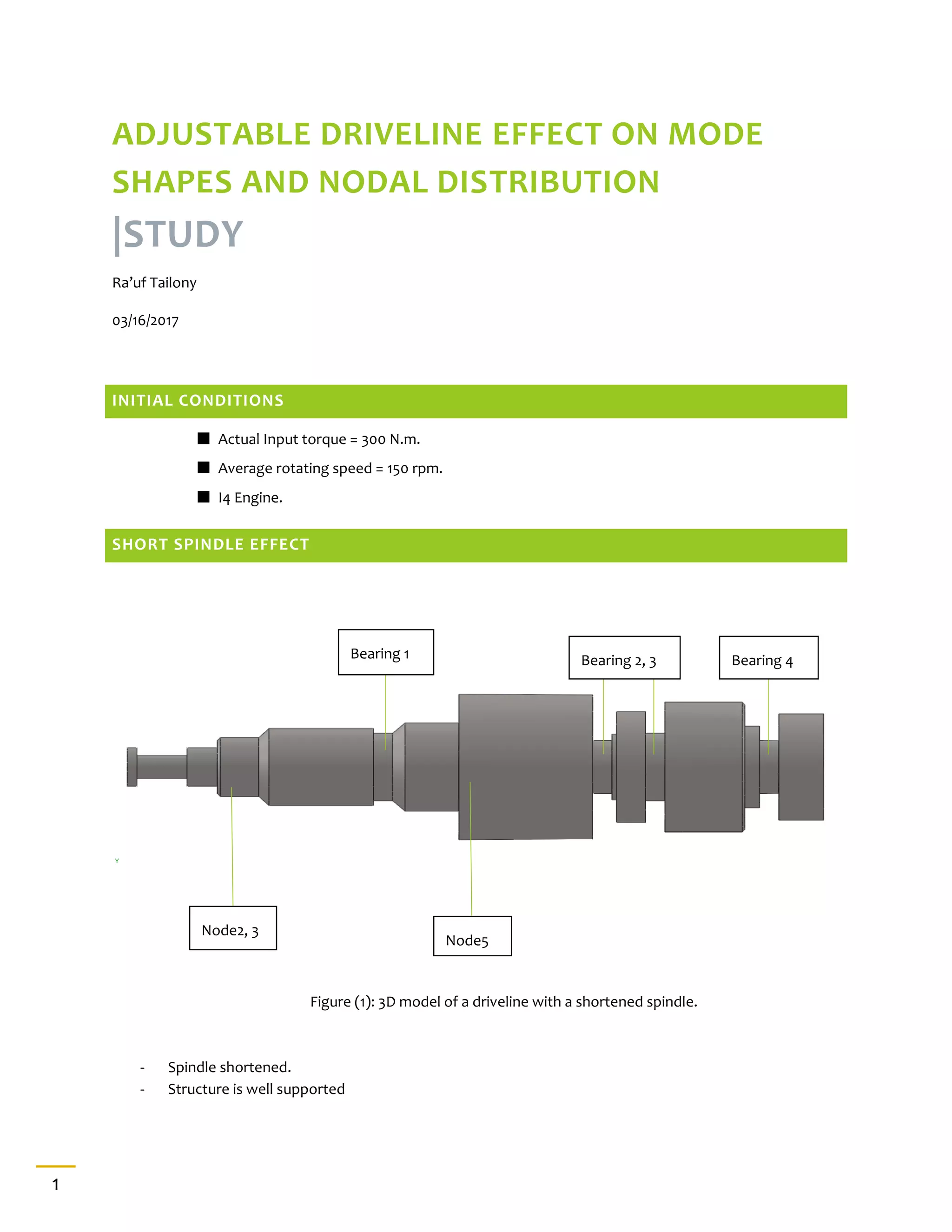
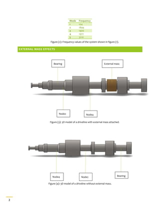
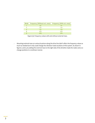

The document analyzes the impact of an adjustable driveline on mode shapes and nodal distribution, using a 3D model to illustrate findings. It presents figures showing frequency values with and without external mass applied to the driveline, indicating that while external mass affects vibration node locations, it does not significantly alter frequency values. The study concludes that the placement of external mass influences node positions in a nonlinear manner.