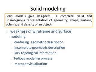
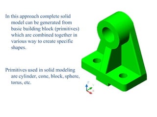
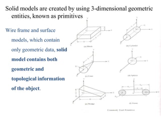
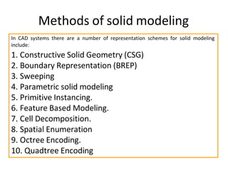
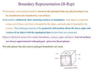
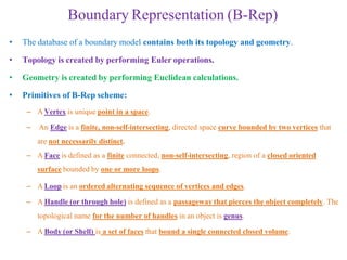
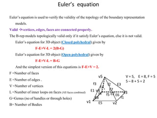
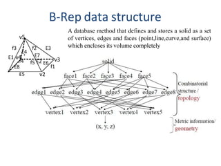
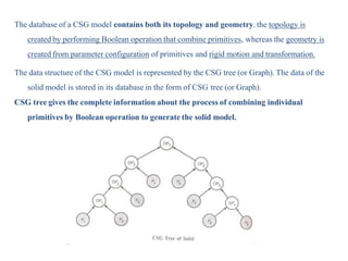
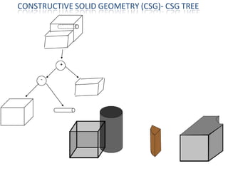
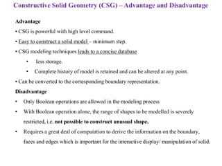
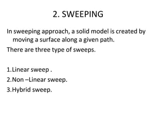
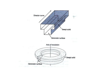
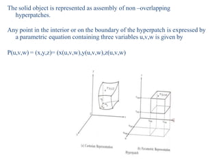
Solid Modeling
Solid models give designers a complete, valid and
unambiguous representation of geometry, shape, surface,
volume, and density of an object.
🞭 weakness of wireframe and surface
modeling
🞭 confusing geometric description
🞭 incomplete geometric description
🞭 lack topological information
🞭 Tedious modeling process
🞭 Improper visualization
Solid modeling
In this approach complete solid
model can be generated from
basic building block (primitives)
which are combined together in
various way to create specific
shapes.
Primitives used in solid modeling
are cylinder, cone, block, sphere,
torus, etc.
Solid models are created by using 3-dimensional geometric
entities, known as primitives
Wire frame and surface
models, which contain
only geometric data, solid
model contains both
geometric and
topological information
of the object.
GEOMETRY AND TOPOLOGY
GEOMETRY- Geometry is the actual dimensions that define the entities of the
object
It consist – length of lines L1,L2,L3
Angle between the lines.
Radius R of circle.
Center P1 of circle.
TOPOLOGY – Topology is the connectivity and associativity of the of the different
entities of the object. It describe the way in which the different entities of the
object are connected.
It consist –
Line L1 shares a point (vertex) with line L2 and circle C1.
Line L2 shares a vertex with lines L1 and L3
Line L3 Shares a vertex with L2& circle C1
Point P1 lies outside the object
Advantages of solid modeling
1.It is easiest and most advanced method of geometric modeling.
2. It contain both geometric data and topological data thus solid models store
more information than wireframe or surface models.
3.It provide better visualization as compared to the wire frame and surface model.
4. Using solid model, it is possible to calculate the properties such as
mass,volume,moment of inertia.
5.Solid modeling produces accurate designs, improves the quality of design
provides complete three- dimensional definition of the objects.
limitation
1. It is not possible to create the solid models automatically from the wire
frame or surface model.
2. Solid model require more CPU time to retrieve, edit or update the model.
In CAD systems there are a number of representation schemes for solid modeling
include:
1. Constructive Solid Geometry (CSG)
2. Boundary Representation (BREP)
3. Sweeping
4. Parametric solid modeling
5. Primitive Instancing.
6. Feature Based Modeling.
7. Cell Decomposition.
8. Spatial Enumeration
9. Octree Encoding.
10. Quadtree Encoding
Methods of solid modeling
Boundary Representation (B-Rep)
The boundary representation model is based on the principal that any physical object can
be considered to be bounded by a set of faces.
Solid model is defined by their enclosing surfaces or boundaries. And object is created by
using a set of faces, each face is bounded by the edges, and each edge is bounded by the
vertices. This technique consists of the geometric information about the faces, edges and
vertices of an object with the topological data on how these are connected.
Object is defined in terms of its surface boundaries, vertices, edges and faces. Curved surfaces
are always approximated with polygons –piecewise linear/planar.
Not only planar but also convex polygon boundaries are used.
Boundary Representation (B-Rep)
• The database of a boundary model contains both its topology and geometry.
• Topology is created by performing Euler operations.
• Geometry is created by performing Euclidean calculations.
• Primitives of B-Rep scheme:
– A Vertex is unique point in a space.
– An Edge is a finite, non-self-intersecting, directed space curve bounded by two vertices that
are not necessarily distinct.
– A Face is defined as a finite connected, non-self-intersecting, region of a closed oriented
surface bounded by one or more loops.
– A Loop is an ordered alternating sequence of vertices and edges.
– A Handle (or through hole) is defined as a passageway that pierces the object completely. The
topological name for the number of handles in an object is genus.
– A Body (or Shell) is a set of faces that bound a single connected closed volume.
Euler’s equation
Euler’s equation is used to verify the validity of the topology of the boundary representation
models.
Valid vertices, edges, faces are connected properly.
The B-rep models topologically valid only if it satisfy Euler’s equation, else it is not valid.
Euler’s equation for 3D object (Closed polyhedral) given by
F-E+V-L = 2(B-G)
Euler’s equation for 3D object (Open polyhedral) given by
F-E+V-L = B-G
And the simplest version of this equations is F-E+V = 2.
F =Number of faces
E =Number of edges .
V =Number of vertices
L =Number of inner loops on faces (All faces combined)
G=Genus (no of handles or through holes)
B= Number of Bodies
V = 5, E = 8, F = 5
5 – 8 + 5 = 2
f4
E4
f2 E3
E7
E8
E5
f5 E2 E6
v2
v3
f1
f3
E1 v4
v5
v1
f4
E4
f2 E3
E7
E8
E5
f5 E2 E6
v2
v3
f1
f3
E1 v4
v5
B-Rep data structure
A database method that defines and stores a solid as a set
of vertices, edges and faces (point,line,curve,and surface)
which encloses its volume completely
Boundary Representation (B-Rep) validity
• System must validate topology of created solid.
• B-Rep has to fulfill certain conditions to disallow self intersecting and open objects.
This condition include:
– Each edge should adjoin exactly two faces and have a vertex at each end.
– Vertices are geometrically described by point coordinates.
– At least three edges must meet at each vertex.
– Faces are described by surface equations.
– The set of faces forms a complete skin of the solid with no missing parts.
– Each face is bordered by an ordered set of edges forming a closed loop.
– Faces must only intersect at common edges or vertices.
– The boundaries of faces do not intersect themselves.
 Valid B-Reps are unambiguous.
 Not fully unique, but much more so than CSG
 Potential difference exists in division of
– Surfaces into faces.
– Curves into edges
 Capability to construct unusual shapes that would not be possible with the available
CSG. Ex: aircraft fuselages, swing shapes
 Less computational time to reconstruct the image
 Requires more storage
 More prone to validity failure than CSG
 Model display limited to planar faces and linear edges
 complex curve and surfaces only approximated
Advantages and limitations
Constructive Solid Geometry (CSG)
• CSG is the most popular and widely used approach to create the solid model of the
object.
• A CSG model is based on the topological notion that a physical object can be
divided into a set of primitives (basic elements or shapes) that can be combined in a
certain order following a set of rules (Boolean operations) to form the object.
• In CSG approach, a solid model of an object is created by using three dimensional
geometric entities, known as primitives. Objects are represented as a combination of
simpler solid objects (primitives).
• The primitives are such as cube, cylinder, cone, torus, sphere, blocks etc.
• These primitives (two or more) can be combined by a mathematical SET of Boolean
operation to create a desired model.
Solid models are created by using 3-dimensional geometric
entities, known as primitives
• Structuring and combining the primitives of the solid model in graphics data base
is achieved by the use of Boolean operations.
• The Boolean operation are-
• Union(U) –used to combine two primitives.
• Intersection(∩) - used to get common volume in two primitives.
• Subtraction(-) – used to subtract one primitive from the other.
🞭 Union
🞭 The sum of all points in each
of two defined sets. (logical
“OR”)
🞭 Also referred to as Add,
Combine, Join, Merge
• Intersection
– Those points common to each of
two defined sets (logical “AND”)
– Set must share common volume
– Also referred to as common,
conjoin
• Difference
– The points in a source set minus the points common to a second set. (logical “NOT”)
– Also referred to as subtraction, remove, cut
The database of a CSG model contains both its topology and geometry. the topology is
created by performing Boolean operation that combine primitives, whereas the geometry is
created from parameter configuration of primitives and rigid motion and transformation.
The data structure of the CSG model is represented by the CSG tree (or Graph). The data of the
solid model is stored in its database in the form of CSG tree (or Graph).
CSG tree gives the complete information about the process of combining individual
primitives by Boolean operation to generate the solid model.
+
-
CONSTRUCTIVE SOLID GEOMETRY (CSG)- CSG TREE
Advantage
• CSG is powerful with high level command.
• Easy to construct a solid model – minimum step.
• CSG modeling techniques leads to a concise database
• less storage.
• Complete history of model is retained and can be altered at any point.
• Can be converted to the corresponding boundary representation.
Disadvantage
• Only Boolean operations are allowed in the modeling process
• With Boolean operation alone, the range of shapes to be modelled is severely
restricted, i.e. not possible to construct unusual shape.
• Requires a great deal of computation to derive the information on the boundary,
faces and edges which is important for the interactive display/ manipulation of solid.
Constructive Solid Geometry (CSG) – Advantage and Disadvantage
2. SWEEPING
In sweeping approach, a solid model is created by
moving a surface along a given path.
There are three type of sweeps.
1.Linear sweep .
2.Non –Linear sweep.
3.Hybrid sweep.
LINEAR SWEEP
In linear sweep ,a surface is
moved in a linear or circular
path .
Linear further divided in two
types- translational and
rotational sweep.
In translational sweep a surface
is moved by a given
distance in space in a
direction perpendicular to
the plane of a surface.
it is also know as extrusion
In rotational sweep ,a surface is rotated about an axis of
rotation by a given angle
Non linear sweep
In non linear sweep a surface (curve ) is moved along
the curved path .
Hybrid sweep
In a hybrid sweep ,the two surface are swept in two
different direction and the two resulting swept
volume are combined to form the object model .
3.Parametric solid modeling
In a parametric modeling the solid object are described
mathematically in three dimensional space by the
parametric equation.
The solid object is represented as assembly of non –overlapping
hyperpatches.
Any point in the interior or on the boundary of the hyperpatch is expressed by
a parametric equation containing three variables u,v,w is given by
P(u,v,w) = (x,y,z)= (x(u,v,w),y(u,v,w),z(u,v,w)
4.Feature based modeling
Now a day feature based modeling is most widely
used method of creating models.
This approach is more general than the CSG
approach ,it allow the designer create the complex
parts.
Feature is defined as the combination of shape and
operation to build the part.
The shape is two dimensional sketch .e.g of the
shape are rectangle,square,triangle ,circle, ellipse
etc.
Steps in feature based modeling
1. Create shape (sketches)- first step is to
create the shapes (sketches) .A shape is a two
dimensional profile or cross-section .
2. Create feature- In second step apply, feature
operations to the shape(sketch) to create the
features e.g. – extrude ,revolve,sweep,loft.
3. Combine feature are combine to form the
solid model of the object.
different feature operation are .
1.Extrude
2.Resolve
3.Sweep
4.Loft
5.Shaft
6.Pipe
7.Boss
8.Cut
9.Slot
10.Shell
11.Fillet
12. Fillet
13. chamfer
14. Draft
15. Spiral
16. Spring
17. Thread
extrude
Extrude model is solid model of the object with uniform
thickness.
It requires a sketch and an extrusion vector. The extrusion
vector is always perpendicular to the plane of sketch.
revolve
Resolve feature is used to create axis symmetric objects.
It require a sketch and a revolution vector
sweep
Sweep feature sweep a
sketch or cross section
along a guide curve .
It require a sketch and a
guide curve .
Linear sweep- guide
curve is straight line.
Non-Linear sweep- guide
curve is any curve
other than straight
line.
Loft is a generalization of sweep .Loft blends multiple cross sections
along a guide curve Types- linear and non linear.
1.Linear loft- Linear loft ,guide curve is a straight line .
2. Non Linear loft – guide curve is any curve other than straight line
LOFT
boss
Boss is an addition of an extrude or revolved
feature to a base feature.
CUT
CUT is the subtraction of an extruded or
revolved feature from a base feature
slot
Slot is subtraction of an extruded feature from
a solid or a base feature
Shell
Shell feature is used
to create a thin
walled hollow solid.
Fillet - Fillet feature is
used to round off
or smoothen the
sharp corners and
edges of the solids.
Chamfer – chamfer feature
is used to remove sharp
edges and corners from the
solid by creating beveled
edges.
Draft - Draft feature is
used to create a taper on
the surface of the object.
Input to create draft is face
to be drafted ,draft angle
and neutral angle from
which the draft angle is
measured.
Spiral – spiral feature is
used to create spiral
springs.
Input parameter for
spiral operation are : a
profile to sweep and
sweeping helix curve.
Spring -Spring Feature is
used to create helical
springs.
Input parameter for
spring operation are
profile to sweep and
sweeping helix.
This technique is used to define
families of object ,which is called
generic primitive.
The primitive are defined in term of a
parameter group for e.g a block
primitive is defined by parameter ;
height(h) ,width(w),and depth(D).
By inputting the values of parameter
defining the primitive ,model can
be generated.
In addition to basic primitives ,the
library of generic primitives
(shapes) which are commonly
used is created.
The generic primitive called from
library by its assigned name and
it can be created by inputting the
values of parameters.
PRIMITIVE INSTANCING
Constraint Based Modeling
• A constraint is defined as the geometric condition that
relates two or more entities of model.
• In constrain based modeling ,the designer can add certain
constrains in modeling .for e.g. adding the constraint of
the symmetry to the modeling allows the designer to
modify the part of the model on one side of the
symmetrical axis, then the part of the model on other
side of the symmetrical axis gets modified automatically.
Various constraint are –
Coincident,collinear,concetric,horizontal
,vertical,midpoint,parallel,perpendicular,tangent,symmetry
Solid modeling based application
1. Graphics – solid models can be used to generate
automatically the orthographic view of the object.
It can also be converted into wire-frame models.
2. Design and analysis -
Solid models are used for automatic mass property
calculations .
Other design and analysis applications of solid model
include : finite element analysis, kinematic analysis,
dynamic analysis,
3. Manufacturing- most significance application of
the solid models in this group is the automatic
tool path generation and verification ,dimension
inspection.
4. Inspection and testing : solid model is used in
computer aided inspection (CAI) and computer
aided testing.
• Modeling Facilities Desired
– The geometric modeling features
– The editing or manipulation features
– The display control facilities
– The drafting features
– The programming facility
– The analysis features
– The connecting features
• The geometric modeling features
– Cartesian and polar coordinates
– 2D analytical features
• Points
• Lines
• Arcs
• Circles
• Conics
• Splines
• Fillets
• Chamfers …
• The editing or manipulation features
– Transformations like move, rotate, copy,
scale…
– Editing features like trim, intersection, stretch,
…
• Display control facilities
– Window
– Zoom
– Pan
– Hidden
– Shading
– Animation
– Clipping
• Drafting features
– The facilities can be utilised for the purpose of
transmitting the information in hard copy
• The ability to get various types of lines
• Text handling capacity interms of font
• To store the large number of views such as isometric,
orthographic, section views,…
• It should have automatic or semi-automatic
dimensioning
• programming facility
– The MACRO programming within a CAD system is
useful to program specifically for an application,
making use of all the features available in the
system for either modelling or for any specific
application based on the information generated
during modeling
• GRIP in Unigraphics
• GLUE in CAM-X
• analysis features
– Calculating Area, perimeter, volume, mass, …
– General purpose analyses like FEA
– Assembly facility with the interference or
clearance analysis
– Ability to explode an assembly for manual
preparation
• connecting features
– The internal data format should be well connected
with other allied modules, i.e, an integrated data
base structure would be useful wherein all the
various modules share the common database

unit-iii-solid-modelling NASJNDKABSDCDAS GDJA.pptx

  • 1.
  • 2.
    Solid models givedesigners a complete, valid and unambiguous representation of geometry, shape, surface, volume, and density of an object. 🞭 weakness of wireframe and surface modeling 🞭 confusing geometric description 🞭 incomplete geometric description 🞭 lack topological information 🞭 Tedious modeling process 🞭 Improper visualization Solid modeling
  • 3.
    In this approachcomplete solid model can be generated from basic building block (primitives) which are combined together in various way to create specific shapes. Primitives used in solid modeling are cylinder, cone, block, sphere, torus, etc.
  • 4.
    Solid models arecreated by using 3-dimensional geometric entities, known as primitives Wire frame and surface models, which contain only geometric data, solid model contains both geometric and topological information of the object.
  • 5.
    GEOMETRY AND TOPOLOGY GEOMETRY-Geometry is the actual dimensions that define the entities of the object It consist – length of lines L1,L2,L3 Angle between the lines. Radius R of circle. Center P1 of circle. TOPOLOGY – Topology is the connectivity and associativity of the of the different entities of the object. It describe the way in which the different entities of the object are connected. It consist – Line L1 shares a point (vertex) with line L2 and circle C1. Line L2 shares a vertex with lines L1 and L3 Line L3 Shares a vertex with L2& circle C1 Point P1 lies outside the object
  • 7.
    Advantages of solidmodeling 1.It is easiest and most advanced method of geometric modeling. 2. It contain both geometric data and topological data thus solid models store more information than wireframe or surface models. 3.It provide better visualization as compared to the wire frame and surface model. 4. Using solid model, it is possible to calculate the properties such as mass,volume,moment of inertia. 5.Solid modeling produces accurate designs, improves the quality of design provides complete three- dimensional definition of the objects.
  • 8.
    limitation 1. It isnot possible to create the solid models automatically from the wire frame or surface model. 2. Solid model require more CPU time to retrieve, edit or update the model.
  • 9.
    In CAD systemsthere are a number of representation schemes for solid modeling include: 1. Constructive Solid Geometry (CSG) 2. Boundary Representation (BREP) 3. Sweeping 4. Parametric solid modeling 5. Primitive Instancing. 6. Feature Based Modeling. 7. Cell Decomposition. 8. Spatial Enumeration 9. Octree Encoding. 10. Quadtree Encoding Methods of solid modeling
  • 10.
    Boundary Representation (B-Rep) Theboundary representation model is based on the principal that any physical object can be considered to be bounded by a set of faces. Solid model is defined by their enclosing surfaces or boundaries. And object is created by using a set of faces, each face is bounded by the edges, and each edge is bounded by the vertices. This technique consists of the geometric information about the faces, edges and vertices of an object with the topological data on how these are connected. Object is defined in terms of its surface boundaries, vertices, edges and faces. Curved surfaces are always approximated with polygons –piecewise linear/planar. Not only planar but also convex polygon boundaries are used.
  • 11.
    Boundary Representation (B-Rep) •The database of a boundary model contains both its topology and geometry. • Topology is created by performing Euler operations. • Geometry is created by performing Euclidean calculations. • Primitives of B-Rep scheme: – A Vertex is unique point in a space. – An Edge is a finite, non-self-intersecting, directed space curve bounded by two vertices that are not necessarily distinct. – A Face is defined as a finite connected, non-self-intersecting, region of a closed oriented surface bounded by one or more loops. – A Loop is an ordered alternating sequence of vertices and edges. – A Handle (or through hole) is defined as a passageway that pierces the object completely. The topological name for the number of handles in an object is genus. – A Body (or Shell) is a set of faces that bound a single connected closed volume.
  • 12.
    Euler’s equation Euler’s equationis used to verify the validity of the topology of the boundary representation models. Valid vertices, edges, faces are connected properly. The B-rep models topologically valid only if it satisfy Euler’s equation, else it is not valid. Euler’s equation for 3D object (Closed polyhedral) given by F-E+V-L = 2(B-G) Euler’s equation for 3D object (Open polyhedral) given by F-E+V-L = B-G And the simplest version of this equations is F-E+V = 2. F =Number of faces E =Number of edges . V =Number of vertices L =Number of inner loops on faces (All faces combined) G=Genus (no of handles or through holes) B= Number of Bodies V = 5, E = 8, F = 5 5 – 8 + 5 = 2 f4 E4 f2 E3 E7 E8 E5 f5 E2 E6 v2 v3 f1 f3 E1 v4 v5 v1
  • 16.
    f4 E4 f2 E3 E7 E8 E5 f5 E2E6 v2 v3 f1 f3 E1 v4 v5 B-Rep data structure A database method that defines and stores a solid as a set of vertices, edges and faces (point,line,curve,and surface) which encloses its volume completely
  • 17.
    Boundary Representation (B-Rep)validity • System must validate topology of created solid. • B-Rep has to fulfill certain conditions to disallow self intersecting and open objects. This condition include: – Each edge should adjoin exactly two faces and have a vertex at each end. – Vertices are geometrically described by point coordinates. – At least three edges must meet at each vertex. – Faces are described by surface equations. – The set of faces forms a complete skin of the solid with no missing parts. – Each face is bordered by an ordered set of edges forming a closed loop. – Faces must only intersect at common edges or vertices. – The boundaries of faces do not intersect themselves.
  • 18.
     Valid B-Repsare unambiguous.  Not fully unique, but much more so than CSG  Potential difference exists in division of – Surfaces into faces. – Curves into edges  Capability to construct unusual shapes that would not be possible with the available CSG. Ex: aircraft fuselages, swing shapes  Less computational time to reconstruct the image  Requires more storage  More prone to validity failure than CSG  Model display limited to planar faces and linear edges  complex curve and surfaces only approximated Advantages and limitations
  • 19.
    Constructive Solid Geometry(CSG) • CSG is the most popular and widely used approach to create the solid model of the object. • A CSG model is based on the topological notion that a physical object can be divided into a set of primitives (basic elements or shapes) that can be combined in a certain order following a set of rules (Boolean operations) to form the object. • In CSG approach, a solid model of an object is created by using three dimensional geometric entities, known as primitives. Objects are represented as a combination of simpler solid objects (primitives). • The primitives are such as cube, cylinder, cone, torus, sphere, blocks etc. • These primitives (two or more) can be combined by a mathematical SET of Boolean operation to create a desired model.
  • 20.
    Solid models arecreated by using 3-dimensional geometric entities, known as primitives
  • 21.
    • Structuring andcombining the primitives of the solid model in graphics data base is achieved by the use of Boolean operations. • The Boolean operation are- • Union(U) –used to combine two primitives. • Intersection(∩) - used to get common volume in two primitives. • Subtraction(-) – used to subtract one primitive from the other.
  • 22.
    🞭 Union 🞭 Thesum of all points in each of two defined sets. (logical “OR”) 🞭 Also referred to as Add, Combine, Join, Merge • Intersection – Those points common to each of two defined sets (logical “AND”) – Set must share common volume – Also referred to as common, conjoin • Difference – The points in a source set minus the points common to a second set. (logical “NOT”) – Also referred to as subtraction, remove, cut
  • 25.
    The database ofa CSG model contains both its topology and geometry. the topology is created by performing Boolean operation that combine primitives, whereas the geometry is created from parameter configuration of primitives and rigid motion and transformation. The data structure of the CSG model is represented by the CSG tree (or Graph). The data of the solid model is stored in its database in the form of CSG tree (or Graph). CSG tree gives the complete information about the process of combining individual primitives by Boolean operation to generate the solid model.
  • 29.
  • 30.
    Advantage • CSG ispowerful with high level command. • Easy to construct a solid model – minimum step. • CSG modeling techniques leads to a concise database • less storage. • Complete history of model is retained and can be altered at any point. • Can be converted to the corresponding boundary representation. Disadvantage • Only Boolean operations are allowed in the modeling process • With Boolean operation alone, the range of shapes to be modelled is severely restricted, i.e. not possible to construct unusual shape. • Requires a great deal of computation to derive the information on the boundary, faces and edges which is important for the interactive display/ manipulation of solid. Constructive Solid Geometry (CSG) – Advantage and Disadvantage
  • 31.
    2. SWEEPING In sweepingapproach, a solid model is created by moving a surface along a given path. There are three type of sweeps. 1.Linear sweep . 2.Non –Linear sweep. 3.Hybrid sweep.
  • 33.
    LINEAR SWEEP In linearsweep ,a surface is moved in a linear or circular path . Linear further divided in two types- translational and rotational sweep. In translational sweep a surface is moved by a given distance in space in a direction perpendicular to the plane of a surface. it is also know as extrusion In rotational sweep ,a surface is rotated about an axis of rotation by a given angle
  • 34.
    Non linear sweep Innon linear sweep a surface (curve ) is moved along the curved path .
  • 35.
    Hybrid sweep In ahybrid sweep ,the two surface are swept in two different direction and the two resulting swept volume are combined to form the object model .
  • 36.
    3.Parametric solid modeling Ina parametric modeling the solid object are described mathematically in three dimensional space by the parametric equation.
  • 37.
    The solid objectis represented as assembly of non –overlapping hyperpatches. Any point in the interior or on the boundary of the hyperpatch is expressed by a parametric equation containing three variables u,v,w is given by P(u,v,w) = (x,y,z)= (x(u,v,w),y(u,v,w),z(u,v,w)
  • 38.
    4.Feature based modeling Nowa day feature based modeling is most widely used method of creating models. This approach is more general than the CSG approach ,it allow the designer create the complex parts. Feature is defined as the combination of shape and operation to build the part. The shape is two dimensional sketch .e.g of the shape are rectangle,square,triangle ,circle, ellipse etc.
  • 39.
    Steps in featurebased modeling 1. Create shape (sketches)- first step is to create the shapes (sketches) .A shape is a two dimensional profile or cross-section . 2. Create feature- In second step apply, feature operations to the shape(sketch) to create the features e.g. – extrude ,revolve,sweep,loft. 3. Combine feature are combine to form the solid model of the object.
  • 40.
    different feature operationare . 1.Extrude 2.Resolve 3.Sweep 4.Loft 5.Shaft 6.Pipe 7.Boss 8.Cut 9.Slot 10.Shell 11.Fillet 12. Fillet 13. chamfer 14. Draft 15. Spiral 16. Spring 17. Thread
  • 41.
    extrude Extrude model issolid model of the object with uniform thickness. It requires a sketch and an extrusion vector. The extrusion vector is always perpendicular to the plane of sketch.
  • 42.
    revolve Resolve feature isused to create axis symmetric objects. It require a sketch and a revolution vector
  • 43.
    sweep Sweep feature sweepa sketch or cross section along a guide curve . It require a sketch and a guide curve . Linear sweep- guide curve is straight line. Non-Linear sweep- guide curve is any curve other than straight line.
  • 44.
    Loft is ageneralization of sweep .Loft blends multiple cross sections along a guide curve Types- linear and non linear. 1.Linear loft- Linear loft ,guide curve is a straight line . 2. Non Linear loft – guide curve is any curve other than straight line LOFT
  • 45.
    boss Boss is anaddition of an extrude or revolved feature to a base feature.
  • 46.
    CUT CUT is thesubtraction of an extruded or revolved feature from a base feature
  • 47.
    slot Slot is subtractionof an extruded feature from a solid or a base feature
  • 48.
    Shell Shell feature isused to create a thin walled hollow solid. Fillet - Fillet feature is used to round off or smoothen the sharp corners and edges of the solids.
  • 49.
    Chamfer – chamferfeature is used to remove sharp edges and corners from the solid by creating beveled edges. Draft - Draft feature is used to create a taper on the surface of the object. Input to create draft is face to be drafted ,draft angle and neutral angle from which the draft angle is measured.
  • 50.
    Spiral – spiralfeature is used to create spiral springs. Input parameter for spiral operation are : a profile to sweep and sweeping helix curve. Spring -Spring Feature is used to create helical springs. Input parameter for spring operation are profile to sweep and sweeping helix.
  • 51.
    This technique isused to define families of object ,which is called generic primitive. The primitive are defined in term of a parameter group for e.g a block primitive is defined by parameter ; height(h) ,width(w),and depth(D). By inputting the values of parameter defining the primitive ,model can be generated. In addition to basic primitives ,the library of generic primitives (shapes) which are commonly used is created. The generic primitive called from library by its assigned name and it can be created by inputting the values of parameters. PRIMITIVE INSTANCING
  • 52.
    Constraint Based Modeling •A constraint is defined as the geometric condition that relates two or more entities of model. • In constrain based modeling ,the designer can add certain constrains in modeling .for e.g. adding the constraint of the symmetry to the modeling allows the designer to modify the part of the model on one side of the symmetrical axis, then the part of the model on other side of the symmetrical axis gets modified automatically.
  • 53.
    Various constraint are– Coincident,collinear,concetric,horizontal ,vertical,midpoint,parallel,perpendicular,tangent,symmetry
  • 54.
    Solid modeling basedapplication 1. Graphics – solid models can be used to generate automatically the orthographic view of the object. It can also be converted into wire-frame models. 2. Design and analysis - Solid models are used for automatic mass property calculations . Other design and analysis applications of solid model include : finite element analysis, kinematic analysis, dynamic analysis,
  • 55.
    3. Manufacturing- mostsignificance application of the solid models in this group is the automatic tool path generation and verification ,dimension inspection. 4. Inspection and testing : solid model is used in computer aided inspection (CAI) and computer aided testing.
  • 56.
    • Modeling FacilitiesDesired – The geometric modeling features – The editing or manipulation features – The display control facilities – The drafting features – The programming facility – The analysis features – The connecting features
  • 57.
    • The geometricmodeling features – Cartesian and polar coordinates – 2D analytical features • Points • Lines • Arcs • Circles • Conics • Splines • Fillets • Chamfers …
  • 58.
    • The editingor manipulation features – Transformations like move, rotate, copy, scale… – Editing features like trim, intersection, stretch, …
  • 59.
    • Display controlfacilities – Window – Zoom – Pan – Hidden – Shading – Animation – Clipping
  • 60.
    • Drafting features –The facilities can be utilised for the purpose of transmitting the information in hard copy • The ability to get various types of lines • Text handling capacity interms of font • To store the large number of views such as isometric, orthographic, section views,… • It should have automatic or semi-automatic dimensioning
  • 61.
    • programming facility –The MACRO programming within a CAD system is useful to program specifically for an application, making use of all the features available in the system for either modelling or for any specific application based on the information generated during modeling • GRIP in Unigraphics • GLUE in CAM-X
  • 62.
    • analysis features –Calculating Area, perimeter, volume, mass, … – General purpose analyses like FEA – Assembly facility with the interference or clearance analysis – Ability to explode an assembly for manual preparation
  • 63.
    • connecting features –The internal data format should be well connected with other allied modules, i.e, an integrated data base structure would be useful wherein all the various modules share the common database