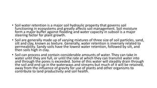
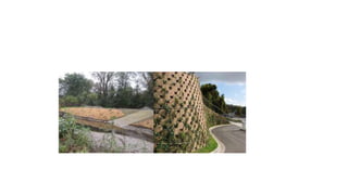
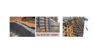
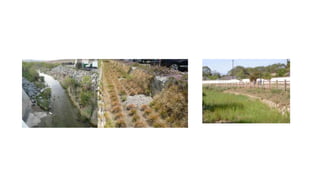
SOIL RETENTION
• Soil water retention is a major soil hydraulic property that governs soil
functioning in ecosystems and greatly affects soil management. Soil moisture
form a major buffer against flooding and water capacity in subsoil is a major
steering factor for plant growth.
• Soil are generally made up of varying mixtures of three size of soil particles, sand,
silt and clay, known as texture. Generally, water retention is inversely related to
permeability. Sandy soils have the lowest water retention, followed by silt, and
then soils high in clay.
• Soil can process and contain considerable amounts of water. They can take in
water until they are full, or until the rate at which they can transmit water into
and through the pores is exceeded. Some of this water will steadily drain through
the soil and end up in the waterways and streams but much of it will be retained,
away from the influence of gravity for use of plants and other organisms to
contribute to land productivity and soil health.
• The maximum amount of water that a given soil can retain is called field capacity,
whereas a soil so dry that the plants cannot liberate the remaining moisture from
the soil particles is said to be at wilting point.
• The process by which soil absorbs water and water goes down is called
percolation.
ROLES OF SOIL WATER RETENTION
A) Soil water retention and organism.
• Soil water retention is essential to life. It provides an ongoing supply of
water to plants between periods of replenishment (infiltration), so as to
allow their continued growth and survival.
B)Soil retention and climate.
• Soil moisture has an effect on the thermal properties of a soil profile,
including conductance and heat capacity.
• The association of soil moisture and soil thermal properties has a
significant effect on temperature-related biological triggers, including
flowering.
C)Soil water retention, water balance and other influences
• The role of soils in retaining water is significant in terms of the hydrological cycle;
including the relative ability of soil to hold moisture and changes in soil moisture over
time:
Soil water that is not retained or used by plants may continue downwards
through the profile and contribute to the water table; this is termed ‘recharge’.
Soils that is at field capacity may preclude infiltration so to increase overland
flow. Both effects are associated with ground and surface water supplies,
erosion and salinity
Soil water can affect the structural integrity or coherence of a soil; saturated soils
can become unstable and result in structural failure and mass movement. Soil
water, its changes over time and management are of interest to geo technicians
and soil conservationists with an interest in maintaining soil stability
SOIL RETENTION SYSTEMS
• Deep excavations for basements and cut and cover structures require
Secure Earth Groundwater Retention Technique used will depend on
method of substructure construction.
Categories
• Open excavation with face of excavation unsupported
• Open excavation with face of excavation supported
• Bottom up excavation
• Top down excavation
• Open Excavation - Used where sufficient space on site and possible to put safe
slope on soil. Retention method is to put embankment at gradient of 45◦ - Soil
must then be assessed - If space restricted, support may need to be considered
Soil Nailing Gabion Walls Toe Walls.
• Bottom Up Excavation - where excavation is temporarily support laterally as
excavation proceeds. Support is not part of the final structure. Methods
Permanent or temporary retaining walls Steel sheet piling with temporary
propping Retaining walls using ground anchors Flying shore props and frame
installed once excavation is complete .
• Top Down Excavation – uses permanent walls and floors progressively to maintain
retention of soil and groundwater.
Advantages
- Reduces temporary works.
- Allows simultaneous substructure and superstructure construction.
- Also has better control of lateral movement and settlement.
A. SOIL NAILING
• Soil nailing is a construction technique that can be used as a remedial measure to
treat unstable natural soil slopes or as a construction technique that allows the
safe over-steepening of new or existing soil slopes.
• The technique involves the insertion of relatively slender reinforcing elements
into the slope – often general purpose reinforcing bars (rebar) although
proprietary solid or hollow-system bars are also available.
• Solid bars are usually installed into pre-drilled holes and then grouted into place
using a separate grout line, whereas hollow bars may be drilled and grouted
simultaneously by the use of a sacrificial drill bit and by pumping grout down the
hollow bar as drilling progresses.
• Bars installed using drilling techniques are usually fully grouted and installed at a
slight downward inclination with bars installed at regularly spaced points across
the slope face. Alternatively a flexible reinforcing mesh may be held against the
soil face beneath the head plates.
• Soil nailing is an earth retention technique using grouted tension-resisting
steel elements (nails) that can be design for permanent or temporary
support. The walls are generally constructed from the top down.
• Near-horizontal holes are drilled into the exposed face at typically 3 to 6
foot centers. Tension-resisting steel bars are inserted into the holes and
grouted. A drainage system is installed on the exposed face, followed by
the application of reinforced shot Crete facing. Precast face panels have
also been used instead of shot Crete. Bearing plates are then fixed to the
heads of the soil nails. The soil at the base of this first stage is then
removed to a depth of about 3 to 6 feet.
• The installation process is repeated until the design wall depth is reached.
The finished soil nails produce a zone of reinforced ground.
• Soil nail components may also be used to stabilize retaining walls or
existing fill slopes embankments and levees); this is normally undertaken as
a remedial measure.
• Factors considered in determining if soil nailing would be an effective
retention technique are as follows.
 The existing ground conditions should be examined.
 The advantages and disadvantages for a soil nail wall should be
assessed for the particular application being considered. Then
other systems should be considered for the particular application.
Cost of the soil nail wall should be considered.
• Soil nailing equipment is small enough that it can easily negotiate
restricted access. For existing steep slopes, such as bluffs or existing
retaining walls, the soil nails can be installed from crane-suspended
working platforms. Soil nails can also be installed directly beneath
existing structures adjacent to excavations.
• Soil nailing has been used to stabilize slopes and landslides, provide
earth retention for excavations for buildings, plants, parking
structures, tunnels, deep cuts, and repair existing retaining walls.
• Soil nailing is a construction technique used to reinforce soil to make
it more stable.
• It is just an alternate to retaining wall structures.
• As the excavation proceeds, the shot Crete, concrete or other grouting
materials are applied on the excavation face to grout the reinforcing steel
or nails. These provide stability to the steep soil slope.
• The first application of soil nailing was implemented in 1972 for a railroad
widening project near Versailles, France. Soil nails were used to stabilize an
18 m high slope consisting of sandy soil. This method proved to be more
cost-effective, while at the same time cut down the construction time
when compared to other conventional support methods.
• Soil nailing technique is used for slopes or excavations alongside highways,
railway lines etc. Following figure shows soil nailing in railway construction:
Types of Soil Nailing
• There are various types of soil nailing techniques:
• 1. Grouted Soil Nailing:
• In this type of soil nailing, the holes are drilled in walls or slope face and then nails are inserted in
the pre-drilled holes. Then the hole is filled with grouting materials such as concrete, shotcrete
etc.
• 2. Driven Nails:
• Driven nailing is used for temporary stabilization of soil slopes. In this method, the nails are driven
in the slope face during excavation. This method is very fast, but does not provide corrosion
protection to the reinforcement steel or nails.
• 3. Self-drilling Soil Nail:
• In this method, the hollow bars are used. Hollow bars are drilled into the slope surface and grout
is injected simultaneously during the drilling process. This method of soil nailing is faster than
grouted nailing. This method provides more corrosion resistance to nails than driven nails.
Fig: Soil nailing Details (Image source: contechsystems.
4. Jet Grouted Soil Nail:
• In this method, jets are used for eroding the soil for creating holes in
the slope surface. Steel bars are then installed in this hole and
grouted with concrete. It provides good corrosion protection for the
steel bars (nails).
5. Launched Soil Nail:
• In this method of soil nailing, the steel bars are forced into the soil
with very high speed using compressed air mechanism. The
installation of soil nails are fast, but control over length of bar
penetrating the ground is difficult.
B. RETAINING WALL
• Retaining walls are structures designed to restrain soil to unnatural slopes.
They are used to bound soils between two different elevations often in
areas of terrain possessing undesirable slopes or in areas where the
landscape needs to be shaped severely and engineered for more specific
purposes like hillside farming or roadway overpasses
• A retaining wall is a structure designed and constructed to resist the lateral
pressure of soil when there is a desired change in ground elevation that
exceeds the angle of repose of the soil.
• A basement wall is thus one kind of retaining wall. But the term usually
refers to a cantilever retaining wall, which is a freestanding structure
without lateral support at its top. These are cantilevered from a footing
and rise above the grade on one side to retain a higher level grade on the
opposite side. The walls must resist the lateral pressures generated by
loose soils or, in some cases, water pressures
• Every retaining wall supports a “wedge” of soil. The wedge is defined as the
soil which extends beyond the failure plane of the soil type present at the
wall site, and can be calculated once the soil friction angle is known. As the
setback of the wall increases, the size of the sliding wedge is reduced. This
reduction lowers the pressure on the retaining wall.
• The most important consideration in proper design and installation of
retaining walls is to recognize and counteract the tendency of the retained
material to move downslope due to gravity. This creates lateral earth
pressure behind the wall which depends on the angle of internal friction
(phi) and the cohesive strength (c) of the retained material, as well as the
direction and magnitude of movement the retaining structure undergoes.
• Lateral earth pressures are zero at the top of the wall and – in
homogenous ground – increase proportionally to a maximum value at
the lowest depth. Earth pressures will push the wall forward or
overturn it if not properly addressed. Also, any groundwater behind
the wall that is not dissipated by a drainage system causes hydrostatic
pressure on the wall. The total pressure or thrust may be assumed to
act at one-third from the lowest depth for lengthwise stretches of
uniform height.
Various types of retaining walls.
C. GABION BASKETS
• A gabion wall is a retaining wall made of stacked stone-filled gabions
tied together with wire. Gabion walls are usually battered(angled
back towards the slope), or stepped back with the slope, rather than
stacked vertically
• Gabions are rectangular galvanized wire baskets filled with stones
used as pervious, semi flexible building blocks for slope and channel
stabilization. Live rooting branches may be placed between the rock-
filled baskets.
• Gabions protect slopes and stream banks from the erosive forces of moving
water. Rock filled gabion baskets or mattresses can be used as retaining
walls for slopes, to armor the bed and/or banks of channels, or to divert
flow away from eroding channel sections. Rock-filled or vegetated rock
gabions are used on stream bank sections subject to excessive erosion due
to increased flows or disturbance during construction.
• Gabions can be specified where flow velocities exceed 6 ft. /sec and where
vegetative stream bank protection alone is not sufficient.
• Gabions can be used to construct deflectors or groins intended to divert
flow away from eroding stream bank sections. Gabions are also used to
construct retaining walls and grade control structures. Gabion walls are
appropriate where:
 The vertical integrity of a soil bank needs a higher tensile strength to reduce sloughing of the
stream bank.
There is moderate to excessive sub-surface water movements that may be creating erosion and
damaging other types of non-permeable structures.
 An excessively steep stream bank must be stabilized and vegetative or extreme mechanical
means of stabilization (i.e., pulling back bank) are not feasible due to site conditions.
 Where slope must be modified while heavy machinery is unavailable to the site.
 Fill must be disposed of along an eroding stream bank (fill can be placed behind gabion to
modify slope).
 A retaining or toe wall is needed to stabilize the slope.
 Rock riprap is an appropriate practice but the available or desired rock size (smaller) is not
sufficient alone to resist the expected shear stress exerted on the revetment. Gabions allow the
use of a smaller size rock than would be possible without the wire baskets because the rock is
bound by the wire mesh, creating a more monolithic structure.
• This type of soil strengthening, often also used without an outside
wall, consists of wire mesh "boxes", which are filled with roughly cut
stone or other material. The mesh cages reduce some internal
movement and forces, and also reduce erosive forces. Gabion walls
are free-draining retaining structures and as such are often built in
locations where ground water is present. However, management and
control of the ground water in and around all retaining walls is
important
Using gabion baskets for retaining walls.
• A “dry” retaining wall, which means that they have no mortar and are incredibly
well draining (no water build up)
• Can effectively stabilize a slope and control erosion on your property
• Rectangle wire baskets are formed onsite; arrive like a flat pack
• A range of standard and custom made sizes are available to accommodate
projects of all shapes and sizes
• Suitable for residential and commercial use; we have worked on retaining walls
for backyard patios and train stations
• Are incredibly long lasting, whether you grow vegetation on them or not
• Steel mesh is incredibly strong and designed to withstand all conditions
• Any stones can be chosen to fill the baskets, but selection is usually made based
on colour, availability and price
PRODUCTS
I. DRIVABLE GRASS
• This is a permeable, flexible and plantable concrete pavement system. This
product is made of wet cast, low moisture absorption concrete.
• Drivable Grass is cast with holes to allow for infiltration and root penetration.
• It’s environmentally friendly and a beautiful alternative to poured concrete and
asphalt. Applications for Drivable Grass include pathways, access roads, green
roofs, RV and boat storage, golf card paths, drainage channels, driveways and
more
Competitive advantages
Strength and durability
• Drivable grass has a concrete compressive strength of 5000 psi and low water absorption that
limits wear and cracking. It’s a proven real-life testing for extreme loading.
Flexibility
• Reinforcing grid and grooves in Drivable Grass give it the ability to conform to uneven
contours
Permeability
• Reduces site run-off, promoting ground water recharge and onsite storage.
Lower runoff coefficient
• Helps to reduce storm drain and inlet size.
Quick and easy installation
• Installs in half the time of conventional pavers. Flexibility and design of the product offers
significantly more forgiving placement compared to large rigid blocks.
II. VERDURA
• Verdura retaining wall system is the most plantable, versatile and strongest
Mechanically Stabilized Earth retaining wall on the market today.
• It’s designed with a positive mechanical connection between the block and the
geosynthetic reinforcement. This mechanical connection provides a uniform
distribution of tensional strength that doesn’t rely solely upon frictional forces
generated from a stack-height of the block units or point load from pins or clips.
• Applications for Verdura include garden walls, borders, tiered walls, channel
walls, detention basin walls, screen walls and more.
Competitive advantages
• Easy to curve
• High shear strength
• Low porosity concrete
• High wall approvals
• Lasts a lifetime
• Not sensitive to compaction
• Low impact
• Backfill with scrapers
III. ENVIROFLEX
• This is a tapered, vertically interlocking articulating concrete block system
designed for erosion control use in riverine, channels, or other areas with high
velocity flows that are subjected to scour.
• Each block vertically interlocks with an overlapping connection, eliminating the
block’s ability to protrude relative to other blocks.
• It’s manufactured from fiber reinforced concrete for added tensile strength.
Openings in the block allows for infiltration and groundwater recharge to help
mitigate flooding and storm water pollution. The openings also allow for
vegetation to establish which promotes bio filtration and results in green, natural
and environmentally pleasing appearance
• Applications for Enviroflex include channel lining, retention basins, wetland traffic
crossings, pipeline protection, bridge pier protection, access roads, culvert outlets
and access ramps.
Competitive advantages
• Vertical interlock
• 0’ protrusion
• Easy installation- can be delivered to the installation site and is easily
placed with small track equipment in location where cranes would find it
difficult to reach.
• No cranes needed
• No cables required
TUNNELING
• A tunnel is an underground or underwater passageway, dug through
the surrounding soil/earth/rock and enclosed except for the entrance
and exit.
• Uses of tunnels
• It may be for pedestrians and/or cyclists
• General road traffic
• Motor vehicles
• Rail traffic
• For a canal
• Some tunnels are constructed purely for carrying water (for consumption,
hydroelectric purposes or as sewers)
• Others carry services such as telecommunications cables
• Special tunnels, such as wildlife crossings, are built to allow wildlife to cross
human-made barriers safely
Construction
Tunnels are dug in types of materials varying from soft clay to hard rock.
The method of tunnel construction depends the following factors:
• The ground conditions
• The ground water conditions
• The length and diameter of the tunnel drive
• The depth of the tunnel
• The logistics of supporting the tunnel excavation
• The final use and shape of the tunnel and
• Appropriate risk management.
There are three basic types of tunnel construction in common use:
• Mountain Tunnel
• Shallow-buried Tunnel or Soft Soil Tunnel
• Underwater Tunnel
Mountain Tunnel
• Drilling and blasting (D&B) method
The advancement of long tunnels through hard rock well before
tunnel boring machines (TBMs) were invented relied entirely on the
drill-and-blast method.
1. Drill holes in tunnel surface and install explosives.
2. Detonate the explosive.
3. Remove spoil from tunnel.
4. Install support to the tunnel and prepare for the next blast.
• NATM (New Austrian Tunneling Method)
This method is applied effectively to sections with appropriate
deployment of the terrain and limited water flow. It involves working on
small sections of the face chamber stage by stage, then a primary
construction /lining/ with reinforced cement solution is deployed above it
and after that at certain distance a secondary construction /panelling/ of
the tunnel is being reinforced and covered with concrete by means of a
special movable formwork.
The essence of the “New Austrian tunnelling method” implies
transforming rock masses into support elements. It relies on the inherent
strength of the surrounding rock mass being conserved as the main
component of tunnel support.
• Tunnel Boring Machine (TBM) method
TMB is used as an alternative to drilling and blasting (D&B) methods.
TBMs are used to excavate tunnels with a circular cross section
through a variety of subterranean matter; hard rock, sand or almost
anything in between. Examples of TBMs are listed below:
• AVN Machine
• Earth Pressure Balance Shield Tunneling Machine
• Fluid Supported Mix Shield Tunneling Machine
• Gripper TBM (Both Single and Double)
• HDD Rig
2. Shallow-buried Tunnel or Soft Soil Tunnel
• Shallow tunnels are of a cut-and-cover type (if under water of the
immersed-tube Type). Deep tunnels are excavated, often using a
tunneling shield. For intermediate levels, both methods are possible.
• Cut-and-cover method
1. Sheet piles / diaphragm wall / pipe pile walls are installed to support the excavation.
2. While the excavation continues to the bottom of the tunnel, temporary road decks are placed on the existing
road surface to ensure smooth vehicular and pedestrian traffic flow.
3. Construction of station concourse and platforms continues underneath the temporary road decks.
4. The road surface is reinstated after construction of the station concourse and platform is completed.
• Bottom-up method: A trench is excavated, with ground support as
necessary, and the tunnel is constructed in it. The tunnel may be of in
situ concrete, precast concrete, precast arches, or corrugated steel
arches; in early days brickwork was used. The trench is then carefully
back-filled and the surface is reinstated.
• Top-down method: Side support walls and capping beams are
constructed from ground level by such methods as slurry walling or
contiguous bored piling. Then a shallow excavation allows making the
tunnel roof of precast beams or in situ concrete. The surface is then
reinstated except for access openings. This allows early reinstatement
of roadways, services and other surface
• Shield method
The mechanized shield method is applied in the construction of
tunnels in the central part of the city, where the tunnels are of
considerable length; where archaeological sites are present, as well as
to avoid open excavation works of considerable length along the
major boulevards.
The machine is pushed forward by a system of hydraulic jacks, stuck
in the tunnel construction in the back part of the shieldThe Shield
method uses one or two shields (large metal cylinder) to cut out a
tunnel through the soft ground. A rotating cutting wheel is located at
the front end of the shield.
• Underwater Tunnel
• Immersed-tube method
The immersed tube tunnel technique uses hollow box sectioned
tunnel elements that have been prefabricated in reinforced concrete.
These are floated out into the harbor and placed into a trench that
was pre-dredged in the harbor bed. When in position, the elements
are joined together to form a tunnel. The trench is then refilled and
the harbor bed returned to its original level.
CULVERTS
• Culverts are structures that allow the flow of water under a trail,
road, railroad thus helping to direct unwanted water away, minimize
erosion and buildup of stagnant water.
• If a section of a road lies in a depressed area of ground or a region
subject to flooding, a culvert should be installed to facilitate drainage.
• Technically, only an enclosed tunnel under a road can be classified as
a culvert.
• Culverts are a vital part of the system used to drain roads and drives,
keeping them safe and extending their lifetimes
Difference between bridges and culverts
• Culverts differ from bridges in that bridges allow for the passage of
people and cars over waer bodies while culverts allow for the passage
of water below pavements and roads.
Materials used in culvert construction
• Culverts are generally constructed out of:- Concrete
- Galvanized steel
- Aluminium or
- PVC
• The material used in a project depends on cost, span, discharge
quantity, topography, soil chemistry or any existing policies.
• Type of Culverts
• 1. Pipe Culvert
• 2. Pipe Arch Culvert
• 3. Box Culvert
• 4. Bridge Culvert
• 5. Arch Culvert
Pipe culverts
• Pipe culverts are made of smooth steel, corrugated metal, or concrete
material. Their primary purpose is to convey water under roads.
Round culverts are best suited to medium and high stream banks
Pipe Arch Culverts
• Pipe-arch culverts provide low clearance, openings suitable for large
waterways, and are more aesthetic. They may also provide a greater
hydraulic advantage to fishes at low flows
Box Culvert
• Box culverts are used to transmit water during brief runoff periods.
Theses are usually used by wildlife because they remain dry most of
the year. They can have an artificial floor such as concrete. Box
culverts generally provide more room for wildlife passage than large
pipe culverts. Box culverts are usually made up of Reinforced
Concrete (RCC)
Arch Culvert
• A pipe arch culvert is a round culvert reshaped to allow a lower
profile while maintaining flow characteristics. It is good for
installations with shallow cover.
• Materials used for arch culverts are RCC, Corrugated Metal or Stone
Masonry.
Design of culverts
• Many Engineering and technical aspects.
 Flood frequency
Site criteria
Design criteria
Culvert materials
Culvert inlets
Wingwalls
Aprons
Protection works
75
Flood frequency
• Culverts must be designed to accommodate the
following
• Design floods for various structures were as
follows:
• Bridges - discharges of 50 year return period
• Box culverts - discharges of 25 year return period
• Pipe culverts - volumes of a 10-year return period
76
Design of culverts
The most difficult aspect is to get an accuratae value
of the discharge
EG a commonly used model for flood estimation is
Q = 0.278CIA m3/sec
 Q = design flood for the crossing
 C is a factor varying from
0.1 for forested catchments
0.5 for heavily tilled land
1.0 for highly paved catchments to near
 I is rainfall intensity from meteorological department
 A is the catchment area from
77
Design of Culverts
• Site criteria and sizing
• This will influence the choice of the culvert for the crossing
• The longitudinal slope will directly affect velocity of the
flood across the culvert
• V = (R2/3S1/2)/n
• V = velocity (m/sec)
• R = Hydraulic radius (A/P)
• A = Cross section area
• P = Wetted perimeter
• S = Longitudinal Slope
78
ACCESS ROADS
ACCESS ROADS
• Each road network has to fulfil three fundamental functions to allow each road user to:
− be able to go from origin to destination (flow function);
− be able to enter and leave an area with scattered destinations (area distributor function);
− be able to access properties alongside a road or street (access function)
• An access road is a road that provides entry into and out of an area, a region of approach
or another road, especially a motorway, a main highway .
• They are used to provide temporary access into and through a construction site.
• Access roads are just that; roads only designed for access to the functions on it, be they
residential properties, retail, schools, or work. They should not carry motor traffic
travelling elsewhere.
• This is also known as a frontage roads which is a local road running parallel to a higher-
speed, limited access road. It is often used to provide way to a property that lies within
another property. For example, to private driveways, shops, houses, industries or farms.
The chosen type of design will depend on, namely:
In situ soil characteristics
Local weather
Load to be supported
If heavy machinery is to be utilized
• LOCATION.
• Access roads should majorly located at points where construction
traffic is heavy, and where there is need to access the site. Avoid
placing access roads in wetlands, flood plains. If such sites are
permitted, careful construction is needed with allowances for
drainage.
• CHARACTERISTICS.
• Compacted roadway with an open aggregate surface.
• Flared entrances near roadways.
Factors to consider before construction of an
access road
Getting to know the property.
–Maps needed are such as:
• Property Ownership Map (Survey Plot) - to locate property lines
• Topographic Maps - to determine elevations and important landscape
features. Using the topographic map, determine the minimum length
for the road.
• Aerial photographs – to obtain a visual image of your land and the
vegetation and structures on it. Available through the county land
office, Recent aerial images, topographical maps, stream data
• Soil Maps - to identify general slopes and “problem areas.” County
libraries
Be prepared to pay the cost of constructing a good road. The cost of constructing a
road will vary greatly from site to site. The cost may increase due to the following
factors:
i. Steep land - costs increase due to more earth-moving on steep slopes.
ii. Winter construction - costs increase because it takes longer to build.
iii.Rocky land - the costs of moving or blasting rock are high.
iv.Drainage needed - surface and subsurface water must be managed.
v. Low stability soils - extra precautions are required on such sites.
vi.Clearing required - wooded areas must be cleared.
https://www.scribd.com/document/83032834/Guide-to-Access-Roads
Characteristics of rural access roads
• The surfaced width of (rural) access roads may vary between 2.5 and 7.5
metres.
• No centre line marking is provided and the lane edges are marked with a
broken white line.
• The effective lane width (between the broken edge line markings) is
between 2.5 and 3.5 metres and this is reserved for motorized traffic in
both directions.
• On wider cross-sections, the space between the road edge and the broken
lane edge line is used as a cycle lane, whereas on very narrow cross-
sections, the shoulders are hardened with some form of grass-penetrable
paving blocks.
• ADVANTAGES
• It is simple in design, easy to install
and remove.
• Ease of access for maintenance
• Materials may include recycled or
reusable concrete, which may later
be used for road works.
• It can be used in all sites with
disturbed soils, providing a defined
entry point for construction plant
and equipment.
• DISADVANTAGES
• Aggregate may be expensive which
adds costs to the project.
• The need to remove it or pave the
road when the project is complete
• In heavy traffic sites, the roads
require maintenance.
• Limited effectiveness on heavy clay
soil
CONSTRUCTION OF ACCESS ROADS
• The Public Roads and Roads of Access Act was enacted
• One requires to place an application to construct a road of access
Act No. 3 of 1951
Act No. 19 of 1954
Sec. 3 L.N. 256/1963
• One would require to gain a right of way. There may be various
challenges such as an existing fence or enclosure.
• Neglecting of an access road may lead to a court case.
• Owner is allowed to use the access road at any time.
• Traditionally, stone has been used at the access road construction
sites. The roads consist of different layers requiring certain gravel size
distribution and certain treatment. This method is laborious, time
consuming and expensive in terms of cost of stone, transportation,
machinery and labour for the stone layout.
• MATERIALS REQUIRED
• Angular or crushed aggregate, 2-3 inch diameter.
• This will increase effectiveness of the sediment removal, increase
road stability and service life of the access road. An increase of
aggregate size and depth is important for heavier plant and
equipment. Aggregate that may wedge or easily wear out tires should
be avoided
DESIGN SPECIFICATIONS
• Determine the location and construction specifications during the
planning stage.
• Locate, size and design for use by all plant and equipment to be used
on site.
• Address and treat all sediment runoff and cart away from the site.
• Construct the entrance on a firm, compacted subgrade thus reducing
the need for constant maintenance.
• Look for the required permits especially when constructing on
wetlands of floodplains. Precautions should be taken to maintain the
water quality.
Cautions to take on
building an access
road
Access roads cut into dispersive soil
can experience severe erosion.
Road safety signs. This is a
precautionary measure applied to
make aware to public pedestrians
and motorists.
CONSTRUCTION GUIDELINES.
• Construct before starting any
earthworks, excavations or earth
disturbances on site.
• Clear, grade and compact the
access road subgrade and
surrounding area according to
the Grade Practices
Specifications.
• Apply the aggregate in layers,
compacting before the
placement of the next layer.
• Install construction barriers to
keep of fallen material and
unprotected soils.
• At the completion of the project,
remove access road and re-use
or dispose the aggregate
• Once the access road has been
removed, ensure that
sedimentation does not occur.
• Construction of access roads and driveways together with temporary
roads is laid to define site circulation routes and/or provide a suitable
surface for plant movements. This is done in:-
Setting out.
Earthworks.
Paving construction
• Setting out the road
• This activity is usually carried out after the top soil has been removed
using the dimensions given on the layout drawing. The layout could
include straight lengths junctions, hammer heads, turning bays and
intersecting curves.
DISTRIBUTOR ROAD
Earthworks
• This will involve the removal of
topsoil together with vegetation,
scraping and grading the
required area down to formation
level plus the formation of any
cuttings or embankments.
• Suitable plant for these
operations would be tractor
shovel or grader
• Shovels fitted with a 4 in 1
bucket, graders and bulldozers.
Paving construction
• Once the subgrade has been prepared and any drainage or other buried
services installed the construction of the paving can be undertaken.
• Paved surfaces can be either flexible or rigid in format.
Rigid paving Flexible paving
MAINTENANCE
• Access roads should be monitored daily during use.
• The aggregate voids should be filled in and any signs of road-bed failure
should be addressed.
• Inspect and maintain any soil runoff and prevent erosion.
• Clean, add aggregate additional layers, replace the aggregate surface
before buildup causing track-out.
• Keep drainage ways for the access roads clear and clean from solid waste.
• Immediately remove all sediment dropped or eroded onto the access roads
by sweeping or shoveling. However do not sweep the material into the
drains.
• Immediately remove any aggregate that has loosened from the bed.
Inspection to access roads
• Any defect or feature likely to cause an obvious danger by encroachment,
visibility obstruction, damage, ill health or trip hazard is recorded and the
appropriate action taken.
• Hedges, trees and shrubs growing on adjacent land which overhang the
road.
• Check for cracks or gaps in the roads, greater than 50mm deep. The
crowning, rutting, edge deterioration, over-riding and depressions will be
classed as safety defects when they are greater than 75mm over a short
distance.
• Kerbing defects. Individual cracked, chipped, rocking, uneven or missing
kerbs will be classed as safety defects where they represent a tripping
hazard, of a height greater than 20mm (but not close to or behind trees,
street furniture and the like) or outwards in excess of 50mm.
Examples of poor access road maintenance
TECHNOLOGY IN ACCESS
ROAD CONSTRUCTION
• A commonly used technology in access ro
ad construction method is matting.
• A number of mats are put on the ground
and interconnected. Some of them can be
made of recycled material, used repeated
ly and be recycled again.
• Matting is used for various reasons:
i. They are easily shaped. It can be cut to
adapt to fit
ii. Its installation is quick. Even after use, it
can be removed quickly.
iii. Non-deformable
iv. Has anti-slip properties
v. Has a very high load-bearing capacity
• Usually mats are made of high density polyethyle
ne, plywood or aluminium. Mats producers and se
llers emphasize environmental contribution based
on the fact that some mats are made of recycled
materials or can be recycled themselves.
• However, recycling of these materials has large dr
awbacks as these processes are energy demandin
g and there are numerous generated pollutants th
at have to be taken care of. These methods are als
o costly and environmentally unfriendly due to hig
h consumption of fuel and high pollution of air ca
used by transportation.
• Old asphalt road beds can be pulverized and mixe
d with other road technology products to produce
new road surfaces.
GEOTEXTILE TECHNOLOGY • Asphalt Overlay. Used in asphalt
overlays to reduce reflective
cracking.
• Separation. Used between two
dissimilar materials, such as an open
graded base and a clay subgrade, in
order to prevent contamination.
• Filtration and Drainage. Used in
place of a graded filter where the
flow of water occurs across
(perpendicular to) the plane of the
geotextile.
Geotextiles are used for many different purposes,
as follows:
• Soil Reinforcement. Used for subgrade
stabilization, slope reinforcement, and
mechanically stabilized earth retaining
walls. Sediment Control. Used as silt fences
to trap sediment on-site.
• Erosion Control. Installed along channels,
under riprap, and used for shore and beach
protection.
Geotextile rolled out to provide separation
Geotextile providing drainage
Bridge Planning
• Traffic Studies –
• give geometrical width and geometry
• Hydrological Studies –
• Provide the bridge opening
• Geotechnical Studies –
• foundation considerations
120
120
Bridge Planning
• Environmental Considerations –
• Not to intrude to the environments
• Alternatives for Bridge Type –
• Several option options some time are available to the designers
• Bridge Selection and Detailed Design
121
121
BRIDGE SPANS AND CLASSIFICATIONS
Small Span Bridges (up to 15m)
Medium Span Bridges (up to 50m)
Large Span Bridges (50-150m)
Extra Large ( Long ) Span Bridges (over 150m)
124
Small Span Bridges (up to 15m)
Culvert Bridge
Slab Bridges
T-Beam Bridge
Wood Beam Bridge
Pre-cast Concrete Box Beam Bridge
Pre-cast Concrete I-Beam Bridge
Rolled Steel Beam Bridge
125
Medium Span Bridges (up to 50m)
Pre-cast Concrete Box Beam & Pre-cast Concrete I-Beam
Composite Rolled Steel Beam Bridge
Composite Steel Plate Girder Bridge
Cast-in-place RCC Box Girder Bridge
Cast-in-place Post-Tensioned Concrete Box Girder
Composite Steel Box Girder
126
Medium Span Bridges (up to 50m)
• Girder Bridge – Globe Cinema Interchange (20-25 m spans – RC
Girders)
127
Large Span Bridges (50 to 150m)
Composite Steel Plate Girder Bridge
Cast-in-place Post-Tensioned concrete Box Girder
Post-Tensioned Concrete Segmental Construction
Concrete Arch and Steel Arch
128
Extra Large (Long) Span Bridges
(Over 150m)
Cable Stayed Bridge
Suspension Bridge
Girder Bridges
• Widely constructed in this country
• Usually used for Short and Medium spans
• Carry load in Shear and Flexural bending
• Economical and long lasting solution for vast
majority of bridges
• Decks and girder usually act together to support the
entire load in highway bridges
Arch Bridge
• Arch action reduces bending moments ( that
is Tensile Stresses )
• Economical as compared to equivalent
straight simply supported Girder or
Truss bridge
• Very suited to a Valley with dry rock slopes
135
• Classic arch form tends to favor Concrete as
a construction material
• Curved shaped is always very pleasing and
arch bridges can be regarded as a beautiful
structures
Arch Bridge
137
Truss Bridge
• The primary member forces are axial loads
• The open web system permits the use of a
greater overall depth than for an
equivalent solid web girder, hence reduced
deflections and rigid structure
• Both these factors lead to Economy in
material and a reduced dead weight
• These advantages are achieved at the
expense of increased fabrication and
maintenance costs
Truss Bridge
• It’s a light weight structure it can be
assembled member by member using
lifting equipment of small capacity.
• For moderate spans its best to provide a
simple and regular structure
• The bridge to Chiromo is a truss bridge
Suspension Bridge
• Major element is a flexible cable, shaped and
supported in such a way that it transfers the loads
to the towers and anchorage
• This cable is commonly constructed from High
Strength wires, either spun in situ or formed from
component, spirally formed wire ropes. In either
case allowable stresses are high of the order of
600 N/mm2 (allowable stress in reinforcing steel
is 230 N/mm2 )
• The deck is hung from the cable by Hangers
constructed of high strength ropes in tension 141
142
Cable-stayed Bridge
• Cables radiate from the support to the bridge
• When the cables are arranged in the single plane, at
the longitudinal center line of the deck, the
appearance of the structure is simplified
• Avoids cable intersections when the bridge is
viewed obliquely
143
FACTORS CONSIDERED IN DECIDING BRIDGE
TYPE
•Geometric Conditions of the Site
•Subsurface Conditions of the Site
•Functional Requirements
•Economics and Ease of Maintenance
•Construction and Erection Consideration
The factors are related to economy, safety
Geometric Conditions of the Site
• The type of bridge selected will always depend on
the horizontal and vertical alignment of the
highway route and on the clearances above and
below the roadway
• Relatively high bridges with larger spans over
navigable waterways will require a different bridge
type than one with medium spans crossing a flood
plain
Subsurface conditions of the soil
 The foundation soils at a site will determine whether
abutments and piers can be founded on spread
footings, driven piles, or drilled shafts
• Drainage conditions on the surface and below ground
must be understood because they influence the
magnitude of earth pressures, movement of
embankments, and stability of cuts or fills
Functional Requirements
• Bridge must function to carry present and future
volumes of traffic.
• Decisions must be made on the number of lanes of
traffic, inclusion of sidewalks and/or bike paths,
whether width of the bridge deck should include
medians, drainage of the surface waters, future
wearing surface.
• In the case of stream and flood plain crossings,
the bridge must continue to function during periods
of high water and not impose a severe
constriction or obstruction to the flow of
water or debris.
• Must accommodate the flood and leave space
at the top known as freeboard
Economic and ease of maintenance
• The initial cost and maintenance cost over the life of the bridge govern
when comparing the economics of different bridge types.
• A general rule is that the bridge with the minimum number of spans,
fewest deck joints, and widest spacing of girders will be the most
economical. Reduce the number of spans in a bridge layout by one span, the
construction cost of one pier is eliminated.
• Deck joints are a high maintenance cost item, so minimizing their number
will reduce the life cycle cost of the bridge.
The Nyali bridge in Mombasa
This is a pre-stressed concrete bridge founded
on seabed which had coral deposits, sand and
clay soils matrix proved to a depth of
100metres below the sea bend.
The designers depended on the skin friction
for the centre piers.
The design consisted of 2.0metre diameter
shafts drilled down to depth of 50 metres.
On plan the piles have a rectangular layout of
3x8 piles per pier.
169
PILE FOUNDATION
DEFINITION
This is a type of foundation constructed by inserting a series of piles
into the ground to transmit load(s) of a structure to a low level of
subsoil. A pile is a long cylinder of a strong material such as concrete
that is pushed into the ground to act as a steady support for structures
built on top of it.
Pile foundations are mainly used where;
• There is a layer of weak soil at the surface which cannot support loading
imposed by the building; especially where loading is concentrated.
• There is a high water table making pumping water from foundations costly.
• The subsoil is subject to moisture movement or plastic failure. Where no
firm stratum exists at a reasonable depth and the loading is uneven making
raft foundation inadvisable.
• In presence of highly compressible subsoil e.g. black cotton soil.
• In soils where deep excavations would lead to damage of existing buildings.
CLASSIFICATION
Piles are classified in the following categories;
1. Basic function
• End bearing or Friction/floating
1. Method of fixing
• Replacement or displacement piles
1. Materials
• Wood, steel H and Pipe section, Concrete
CLASSIFICATION BY BASIC FUNCTION
This classification is based on how the piles transmit their loads to the ground.
a. End Bearing pile
• The bottom end of the pile rests on the stratum. e.g. compact gravel, hard clay or
rock. The piles transfer the loads to the firm bearing stratum below the structure by
acting as an ordinary column. Some of the loads are transferred through friction
thus not being entirely end bearing.
b. Friction pile
• They transfer loads mainly by friction to clay and silts. The entire surface of the
pile is involved. The pile does not reach the firm stratum below the ground. They
are also known as floating foundations because the pile appears to be
suspended/floating on the subsoil rather than lying on the firm stratum.
CLASSIFICATION BY METHOD OF FIXING
a. Displacement piles
• The units are driven into the ground to displace subsoil by machinery, displacing
the earth around it, until a predetermined depth is achieved. Depending on the
amount of soil that is pushed out as a pile is driven in, they can be further
classified into;
- Low displacement piles like H-sections and open ended steel tubes
- High displacement piles which are basically solid section piles.
a. Replacement piles
• They are also called bored piles as holes are predrilled. They are used in cohesive
soils for friction piles and where the foundation is in close proximity to existing
buildings and noise and vibrations level allowed is limited.
a. Timber piles
They were mainly used in the traditional construction to support buildings in weak soil.
Trees with exceptionally straight trunks are required. The pile length is limited to the
length of a single tree, about 20m, since one cannot join together two tree trunks. The
entire city of Venice in Italy is famous for being built on wooden piles over the sea
water. Timber piles are relatively cheap to acquire. They are however vulnerable to
damage while driving in hard stones and hard rock. If not well treated, they are subject
to attack by marine borers, in salty water.
b. Steel piles
They are stronger as compared to timber piles. They are easy to join together and can
penetrate through light obstructions. This type of piles can carry very heavy loads. The
main demerit with steel piles is that they are vulnerable to corrosion. Protective
measure must therefore be conducted while installing them. They are also relatively
more expensive as compared to timber.
c. Concrete piles
• These can be categorized as;
In-situ/ cast in place concrete piles.
• These are the most commonly used type of piles. They are relatively
cheap to construct and can be easily cut or extended to the desired
lengths.
• However, they are time consuming to construct as it involves boring
as well as time for the concrete to gain sufficient strength before they
can be used to support the structure.
Precast concrete piles.
• Precast concrete piles offer a more reliable pile as compared to in-situ as a
higher degree of quality is observed in their manufacture. They can be used
for greater depths and are ready to use upon installation.
• They are however not preferred in already built-up areas due to difficulties
in moving them through narrow streets and may cause nuisance while
driving them into the ground.
Pre-stressed concrete piles.
• Pre- stressing is a technique to reduce cracking in concrete by introducing
tensile forces to a concrete member before actual loading. These piles have
a smaller cross-section area in comparison to the other piles made of
concrete and are more durable.
PILE CAPS
• Piles can be used singly to support the load but often it is more
economical to use piles in groups or clusters linked together. Building
loads can be transferred to piles by a thick reinforced-concrete slab,
called a pile-cap footing.
• The pile cap footing should have a minimum thickness of 12mm. The
designed in different shapes depending on the number of piles
embedded on it.
PILE TESTING
At least one pile per scheme should be tested. It should be overloaded
by at least 50% of its working load, which should be held for a day. The
test pile should not form part of the actual foundation.
Methods used include;
1. Jacking against kentledge placed over test pile.
2. Jacking against a beam fixed to anchor piles driven in on two sides of
the test pile.
The end

soil retention in construction -Group 7 powerpoint

  • 1.
  • 2.
    • Soil waterretention is a major soil hydraulic property that governs soil functioning in ecosystems and greatly affects soil management. Soil moisture form a major buffer against flooding and water capacity in subsoil is a major steering factor for plant growth. • Soil are generally made up of varying mixtures of three size of soil particles, sand, silt and clay, known as texture. Generally, water retention is inversely related to permeability. Sandy soils have the lowest water retention, followed by silt, and then soils high in clay. • Soil can process and contain considerable amounts of water. They can take in water until they are full, or until the rate at which they can transmit water into and through the pores is exceeded. Some of this water will steadily drain through the soil and end up in the waterways and streams but much of it will be retained, away from the influence of gravity for use of plants and other organisms to contribute to land productivity and soil health.
  • 3.
    • The maximumamount of water that a given soil can retain is called field capacity, whereas a soil so dry that the plants cannot liberate the remaining moisture from the soil particles is said to be at wilting point. • The process by which soil absorbs water and water goes down is called percolation.
  • 5.
    ROLES OF SOILWATER RETENTION A) Soil water retention and organism. • Soil water retention is essential to life. It provides an ongoing supply of water to plants between periods of replenishment (infiltration), so as to allow their continued growth and survival. B)Soil retention and climate. • Soil moisture has an effect on the thermal properties of a soil profile, including conductance and heat capacity. • The association of soil moisture and soil thermal properties has a significant effect on temperature-related biological triggers, including flowering.
  • 6.
    C)Soil water retention,water balance and other influences • The role of soils in retaining water is significant in terms of the hydrological cycle; including the relative ability of soil to hold moisture and changes in soil moisture over time: Soil water that is not retained or used by plants may continue downwards through the profile and contribute to the water table; this is termed ‘recharge’. Soils that is at field capacity may preclude infiltration so to increase overland flow. Both effects are associated with ground and surface water supplies, erosion and salinity Soil water can affect the structural integrity or coherence of a soil; saturated soils can become unstable and result in structural failure and mass movement. Soil water, its changes over time and management are of interest to geo technicians and soil conservationists with an interest in maintaining soil stability
  • 7.
    SOIL RETENTION SYSTEMS •Deep excavations for basements and cut and cover structures require Secure Earth Groundwater Retention Technique used will depend on method of substructure construction. Categories • Open excavation with face of excavation unsupported • Open excavation with face of excavation supported • Bottom up excavation • Top down excavation
  • 8.
    • Open Excavation- Used where sufficient space on site and possible to put safe slope on soil. Retention method is to put embankment at gradient of 45◦ - Soil must then be assessed - If space restricted, support may need to be considered Soil Nailing Gabion Walls Toe Walls. • Bottom Up Excavation - where excavation is temporarily support laterally as excavation proceeds. Support is not part of the final structure. Methods Permanent or temporary retaining walls Steel sheet piling with temporary propping Retaining walls using ground anchors Flying shore props and frame installed once excavation is complete . • Top Down Excavation – uses permanent walls and floors progressively to maintain retention of soil and groundwater. Advantages - Reduces temporary works. - Allows simultaneous substructure and superstructure construction. - Also has better control of lateral movement and settlement.
  • 10.
    A. SOIL NAILING •Soil nailing is a construction technique that can be used as a remedial measure to treat unstable natural soil slopes or as a construction technique that allows the safe over-steepening of new or existing soil slopes. • The technique involves the insertion of relatively slender reinforcing elements into the slope – often general purpose reinforcing bars (rebar) although proprietary solid or hollow-system bars are also available. • Solid bars are usually installed into pre-drilled holes and then grouted into place using a separate grout line, whereas hollow bars may be drilled and grouted simultaneously by the use of a sacrificial drill bit and by pumping grout down the hollow bar as drilling progresses. • Bars installed using drilling techniques are usually fully grouted and installed at a slight downward inclination with bars installed at regularly spaced points across the slope face. Alternatively a flexible reinforcing mesh may be held against the soil face beneath the head plates.
  • 11.
    • Soil nailingis an earth retention technique using grouted tension-resisting steel elements (nails) that can be design for permanent or temporary support. The walls are generally constructed from the top down. • Near-horizontal holes are drilled into the exposed face at typically 3 to 6 foot centers. Tension-resisting steel bars are inserted into the holes and grouted. A drainage system is installed on the exposed face, followed by the application of reinforced shot Crete facing. Precast face panels have also been used instead of shot Crete. Bearing plates are then fixed to the heads of the soil nails. The soil at the base of this first stage is then removed to a depth of about 3 to 6 feet. • The installation process is repeated until the design wall depth is reached. The finished soil nails produce a zone of reinforced ground. • Soil nail components may also be used to stabilize retaining walls or existing fill slopes embankments and levees); this is normally undertaken as a remedial measure.
  • 12.
    • Factors consideredin determining if soil nailing would be an effective retention technique are as follows.  The existing ground conditions should be examined.  The advantages and disadvantages for a soil nail wall should be assessed for the particular application being considered. Then other systems should be considered for the particular application. Cost of the soil nail wall should be considered.
  • 13.
    • Soil nailingequipment is small enough that it can easily negotiate restricted access. For existing steep slopes, such as bluffs or existing retaining walls, the soil nails can be installed from crane-suspended working platforms. Soil nails can also be installed directly beneath existing structures adjacent to excavations. • Soil nailing has been used to stabilize slopes and landslides, provide earth retention for excavations for buildings, plants, parking structures, tunnels, deep cuts, and repair existing retaining walls. • Soil nailing is a construction technique used to reinforce soil to make it more stable.
  • 14.
    • It isjust an alternate to retaining wall structures. • As the excavation proceeds, the shot Crete, concrete or other grouting materials are applied on the excavation face to grout the reinforcing steel or nails. These provide stability to the steep soil slope. • The first application of soil nailing was implemented in 1972 for a railroad widening project near Versailles, France. Soil nails were used to stabilize an 18 m high slope consisting of sandy soil. This method proved to be more cost-effective, while at the same time cut down the construction time when compared to other conventional support methods. • Soil nailing technique is used for slopes or excavations alongside highways, railway lines etc. Following figure shows soil nailing in railway construction:
  • 16.
    Types of SoilNailing • There are various types of soil nailing techniques: • 1. Grouted Soil Nailing: • In this type of soil nailing, the holes are drilled in walls or slope face and then nails are inserted in the pre-drilled holes. Then the hole is filled with grouting materials such as concrete, shotcrete etc. • 2. Driven Nails: • Driven nailing is used for temporary stabilization of soil slopes. In this method, the nails are driven in the slope face during excavation. This method is very fast, but does not provide corrosion protection to the reinforcement steel or nails. • 3. Self-drilling Soil Nail: • In this method, the hollow bars are used. Hollow bars are drilled into the slope surface and grout is injected simultaneously during the drilling process. This method of soil nailing is faster than grouted nailing. This method provides more corrosion resistance to nails than driven nails.
  • 17.
    Fig: Soil nailingDetails (Image source: contechsystems.
  • 18.
    4. Jet GroutedSoil Nail: • In this method, jets are used for eroding the soil for creating holes in the slope surface. Steel bars are then installed in this hole and grouted with concrete. It provides good corrosion protection for the steel bars (nails). 5. Launched Soil Nail: • In this method of soil nailing, the steel bars are forced into the soil with very high speed using compressed air mechanism. The installation of soil nails are fast, but control over length of bar penetrating the ground is difficult.
  • 20.
    B. RETAINING WALL •Retaining walls are structures designed to restrain soil to unnatural slopes. They are used to bound soils between two different elevations often in areas of terrain possessing undesirable slopes or in areas where the landscape needs to be shaped severely and engineered for more specific purposes like hillside farming or roadway overpasses • A retaining wall is a structure designed and constructed to resist the lateral pressure of soil when there is a desired change in ground elevation that exceeds the angle of repose of the soil. • A basement wall is thus one kind of retaining wall. But the term usually refers to a cantilever retaining wall, which is a freestanding structure without lateral support at its top. These are cantilevered from a footing and rise above the grade on one side to retain a higher level grade on the opposite side. The walls must resist the lateral pressures generated by loose soils or, in some cases, water pressures
  • 22.
    • Every retainingwall supports a “wedge” of soil. The wedge is defined as the soil which extends beyond the failure plane of the soil type present at the wall site, and can be calculated once the soil friction angle is known. As the setback of the wall increases, the size of the sliding wedge is reduced. This reduction lowers the pressure on the retaining wall. • The most important consideration in proper design and installation of retaining walls is to recognize and counteract the tendency of the retained material to move downslope due to gravity. This creates lateral earth pressure behind the wall which depends on the angle of internal friction (phi) and the cohesive strength (c) of the retained material, as well as the direction and magnitude of movement the retaining structure undergoes.
  • 23.
    • Lateral earthpressures are zero at the top of the wall and – in homogenous ground – increase proportionally to a maximum value at the lowest depth. Earth pressures will push the wall forward or overturn it if not properly addressed. Also, any groundwater behind the wall that is not dissipated by a drainage system causes hydrostatic pressure on the wall. The total pressure or thrust may be assumed to act at one-third from the lowest depth for lengthwise stretches of uniform height.
  • 24.
    Various types ofretaining walls.
  • 26.
    C. GABION BASKETS •A gabion wall is a retaining wall made of stacked stone-filled gabions tied together with wire. Gabion walls are usually battered(angled back towards the slope), or stepped back with the slope, rather than stacked vertically • Gabions are rectangular galvanized wire baskets filled with stones used as pervious, semi flexible building blocks for slope and channel stabilization. Live rooting branches may be placed between the rock- filled baskets.
  • 27.
    • Gabions protectslopes and stream banks from the erosive forces of moving water. Rock filled gabion baskets or mattresses can be used as retaining walls for slopes, to armor the bed and/or banks of channels, or to divert flow away from eroding channel sections. Rock-filled or vegetated rock gabions are used on stream bank sections subject to excessive erosion due to increased flows or disturbance during construction. • Gabions can be specified where flow velocities exceed 6 ft. /sec and where vegetative stream bank protection alone is not sufficient. • Gabions can be used to construct deflectors or groins intended to divert flow away from eroding stream bank sections. Gabions are also used to construct retaining walls and grade control structures. Gabion walls are appropriate where:
  • 28.
     The verticalintegrity of a soil bank needs a higher tensile strength to reduce sloughing of the stream bank. There is moderate to excessive sub-surface water movements that may be creating erosion and damaging other types of non-permeable structures.  An excessively steep stream bank must be stabilized and vegetative or extreme mechanical means of stabilization (i.e., pulling back bank) are not feasible due to site conditions.  Where slope must be modified while heavy machinery is unavailable to the site.  Fill must be disposed of along an eroding stream bank (fill can be placed behind gabion to modify slope).  A retaining or toe wall is needed to stabilize the slope.  Rock riprap is an appropriate practice but the available or desired rock size (smaller) is not sufficient alone to resist the expected shear stress exerted on the revetment. Gabions allow the use of a smaller size rock than would be possible without the wire baskets because the rock is bound by the wire mesh, creating a more monolithic structure.
  • 29.
    • This typeof soil strengthening, often also used without an outside wall, consists of wire mesh "boxes", which are filled with roughly cut stone or other material. The mesh cages reduce some internal movement and forces, and also reduce erosive forces. Gabion walls are free-draining retaining structures and as such are often built in locations where ground water is present. However, management and control of the ground water in and around all retaining walls is important
  • 30.
    Using gabion basketsfor retaining walls. • A “dry” retaining wall, which means that they have no mortar and are incredibly well draining (no water build up) • Can effectively stabilize a slope and control erosion on your property • Rectangle wire baskets are formed onsite; arrive like a flat pack • A range of standard and custom made sizes are available to accommodate projects of all shapes and sizes • Suitable for residential and commercial use; we have worked on retaining walls for backyard patios and train stations • Are incredibly long lasting, whether you grow vegetation on them or not • Steel mesh is incredibly strong and designed to withstand all conditions • Any stones can be chosen to fill the baskets, but selection is usually made based on colour, availability and price
  • 33.
    PRODUCTS I. DRIVABLE GRASS •This is a permeable, flexible and plantable concrete pavement system. This product is made of wet cast, low moisture absorption concrete. • Drivable Grass is cast with holes to allow for infiltration and root penetration. • It’s environmentally friendly and a beautiful alternative to poured concrete and asphalt. Applications for Drivable Grass include pathways, access roads, green roofs, RV and boat storage, golf card paths, drainage channels, driveways and more
  • 35.
    Competitive advantages Strength anddurability • Drivable grass has a concrete compressive strength of 5000 psi and low water absorption that limits wear and cracking. It’s a proven real-life testing for extreme loading. Flexibility • Reinforcing grid and grooves in Drivable Grass give it the ability to conform to uneven contours Permeability • Reduces site run-off, promoting ground water recharge and onsite storage. Lower runoff coefficient • Helps to reduce storm drain and inlet size. Quick and easy installation • Installs in half the time of conventional pavers. Flexibility and design of the product offers significantly more forgiving placement compared to large rigid blocks.
  • 36.
    II. VERDURA • Verduraretaining wall system is the most plantable, versatile and strongest Mechanically Stabilized Earth retaining wall on the market today. • It’s designed with a positive mechanical connection between the block and the geosynthetic reinforcement. This mechanical connection provides a uniform distribution of tensional strength that doesn’t rely solely upon frictional forces generated from a stack-height of the block units or point load from pins or clips.
  • 37.
    • Applications forVerdura include garden walls, borders, tiered walls, channel walls, detention basin walls, screen walls and more.
  • 39.
    Competitive advantages • Easyto curve • High shear strength • Low porosity concrete • High wall approvals • Lasts a lifetime • Not sensitive to compaction • Low impact • Backfill with scrapers
  • 40.
    III. ENVIROFLEX • Thisis a tapered, vertically interlocking articulating concrete block system designed for erosion control use in riverine, channels, or other areas with high velocity flows that are subjected to scour. • Each block vertically interlocks with an overlapping connection, eliminating the block’s ability to protrude relative to other blocks.
  • 41.
    • It’s manufacturedfrom fiber reinforced concrete for added tensile strength. Openings in the block allows for infiltration and groundwater recharge to help mitigate flooding and storm water pollution. The openings also allow for vegetation to establish which promotes bio filtration and results in green, natural and environmentally pleasing appearance • Applications for Enviroflex include channel lining, retention basins, wetland traffic crossings, pipeline protection, bridge pier protection, access roads, culvert outlets and access ramps.
  • 43.
    Competitive advantages • Verticalinterlock • 0’ protrusion • Easy installation- can be delivered to the installation site and is easily placed with small track equipment in location where cranes would find it difficult to reach. • No cranes needed • No cables required
  • 45.
  • 46.
    • A tunnelis an underground or underwater passageway, dug through the surrounding soil/earth/rock and enclosed except for the entrance and exit.
  • 47.
    • Uses oftunnels • It may be for pedestrians and/or cyclists • General road traffic • Motor vehicles • Rail traffic • For a canal • Some tunnels are constructed purely for carrying water (for consumption, hydroelectric purposes or as sewers) • Others carry services such as telecommunications cables • Special tunnels, such as wildlife crossings, are built to allow wildlife to cross human-made barriers safely
  • 48.
    Construction Tunnels are dugin types of materials varying from soft clay to hard rock. The method of tunnel construction depends the following factors: • The ground conditions • The ground water conditions • The length and diameter of the tunnel drive • The depth of the tunnel • The logistics of supporting the tunnel excavation • The final use and shape of the tunnel and • Appropriate risk management.
  • 49.
    There are threebasic types of tunnel construction in common use: • Mountain Tunnel • Shallow-buried Tunnel or Soft Soil Tunnel • Underwater Tunnel
  • 50.
    Mountain Tunnel • Drillingand blasting (D&B) method The advancement of long tunnels through hard rock well before tunnel boring machines (TBMs) were invented relied entirely on the drill-and-blast method.
  • 51.
    1. Drill holesin tunnel surface and install explosives. 2. Detonate the explosive. 3. Remove spoil from tunnel. 4. Install support to the tunnel and prepare for the next blast.
  • 52.
    • NATM (NewAustrian Tunneling Method) This method is applied effectively to sections with appropriate deployment of the terrain and limited water flow. It involves working on small sections of the face chamber stage by stage, then a primary construction /lining/ with reinforced cement solution is deployed above it and after that at certain distance a secondary construction /panelling/ of the tunnel is being reinforced and covered with concrete by means of a special movable formwork. The essence of the “New Austrian tunnelling method” implies transforming rock masses into support elements. It relies on the inherent strength of the surrounding rock mass being conserved as the main component of tunnel support.
  • 53.
    • Tunnel BoringMachine (TBM) method TMB is used as an alternative to drilling and blasting (D&B) methods. TBMs are used to excavate tunnels with a circular cross section through a variety of subterranean matter; hard rock, sand or almost anything in between. Examples of TBMs are listed below:
  • 54.
    • AVN Machine •Earth Pressure Balance Shield Tunneling Machine • Fluid Supported Mix Shield Tunneling Machine • Gripper TBM (Both Single and Double) • HDD Rig
  • 55.
    2. Shallow-buried Tunnelor Soft Soil Tunnel • Shallow tunnels are of a cut-and-cover type (if under water of the immersed-tube Type). Deep tunnels are excavated, often using a tunneling shield. For intermediate levels, both methods are possible.
  • 56.
    • Cut-and-cover method 1.Sheet piles / diaphragm wall / pipe pile walls are installed to support the excavation. 2. While the excavation continues to the bottom of the tunnel, temporary road decks are placed on the existing road surface to ensure smooth vehicular and pedestrian traffic flow. 3. Construction of station concourse and platforms continues underneath the temporary road decks. 4. The road surface is reinstated after construction of the station concourse and platform is completed.
  • 57.
    • Bottom-up method:A trench is excavated, with ground support as necessary, and the tunnel is constructed in it. The tunnel may be of in situ concrete, precast concrete, precast arches, or corrugated steel arches; in early days brickwork was used. The trench is then carefully back-filled and the surface is reinstated. • Top-down method: Side support walls and capping beams are constructed from ground level by such methods as slurry walling or contiguous bored piling. Then a shallow excavation allows making the tunnel roof of precast beams or in situ concrete. The surface is then reinstated except for access openings. This allows early reinstatement of roadways, services and other surface
  • 58.
    • Shield method Themechanized shield method is applied in the construction of tunnels in the central part of the city, where the tunnels are of considerable length; where archaeological sites are present, as well as to avoid open excavation works of considerable length along the major boulevards. The machine is pushed forward by a system of hydraulic jacks, stuck in the tunnel construction in the back part of the shieldThe Shield method uses one or two shields (large metal cylinder) to cut out a tunnel through the soft ground. A rotating cutting wheel is located at the front end of the shield.
  • 59.
    • Underwater Tunnel •Immersed-tube method The immersed tube tunnel technique uses hollow box sectioned tunnel elements that have been prefabricated in reinforced concrete. These are floated out into the harbor and placed into a trench that was pre-dredged in the harbor bed. When in position, the elements are joined together to form a tunnel. The trench is then refilled and the harbor bed returned to its original level.
  • 62.
  • 63.
    • Culverts arestructures that allow the flow of water under a trail, road, railroad thus helping to direct unwanted water away, minimize erosion and buildup of stagnant water. • If a section of a road lies in a depressed area of ground or a region subject to flooding, a culvert should be installed to facilitate drainage. • Technically, only an enclosed tunnel under a road can be classified as a culvert. • Culverts are a vital part of the system used to drain roads and drives, keeping them safe and extending their lifetimes
  • 64.
    Difference between bridgesand culverts • Culverts differ from bridges in that bridges allow for the passage of people and cars over waer bodies while culverts allow for the passage of water below pavements and roads.
  • 65.
    Materials used inculvert construction • Culverts are generally constructed out of:- Concrete - Galvanized steel - Aluminium or - PVC • The material used in a project depends on cost, span, discharge quantity, topography, soil chemistry or any existing policies.
  • 66.
    • Type ofCulverts • 1. Pipe Culvert • 2. Pipe Arch Culvert • 3. Box Culvert • 4. Bridge Culvert • 5. Arch Culvert
  • 67.
    Pipe culverts • Pipeculverts are made of smooth steel, corrugated metal, or concrete material. Their primary purpose is to convey water under roads. Round culverts are best suited to medium and high stream banks
  • 69.
  • 70.
    • Pipe-arch culvertsprovide low clearance, openings suitable for large waterways, and are more aesthetic. They may also provide a greater hydraulic advantage to fishes at low flows
  • 71.
  • 72.
    • Box culvertsare used to transmit water during brief runoff periods. Theses are usually used by wildlife because they remain dry most of the year. They can have an artificial floor such as concrete. Box culverts generally provide more room for wildlife passage than large pipe culverts. Box culverts are usually made up of Reinforced Concrete (RCC)
  • 73.
    Arch Culvert • Apipe arch culvert is a round culvert reshaped to allow a lower profile while maintaining flow characteristics. It is good for installations with shallow cover. • Materials used for arch culverts are RCC, Corrugated Metal or Stone Masonry.
  • 75.
    Design of culverts •Many Engineering and technical aspects.  Flood frequency Site criteria Design criteria Culvert materials Culvert inlets Wingwalls Aprons Protection works 75
  • 76.
    Flood frequency • Culvertsmust be designed to accommodate the following • Design floods for various structures were as follows: • Bridges - discharges of 50 year return period • Box culverts - discharges of 25 year return period • Pipe culverts - volumes of a 10-year return period 76
  • 77.
    Design of culverts Themost difficult aspect is to get an accuratae value of the discharge EG a commonly used model for flood estimation is Q = 0.278CIA m3/sec  Q = design flood for the crossing  C is a factor varying from 0.1 for forested catchments 0.5 for heavily tilled land 1.0 for highly paved catchments to near  I is rainfall intensity from meteorological department  A is the catchment area from 77
  • 78.
    Design of Culverts •Site criteria and sizing • This will influence the choice of the culvert for the crossing • The longitudinal slope will directly affect velocity of the flood across the culvert • V = (R2/3S1/2)/n • V = velocity (m/sec) • R = Hydraulic radius (A/P) • A = Cross section area • P = Wetted perimeter • S = Longitudinal Slope 78
  • 80.
  • 81.
    ACCESS ROADS • Eachroad network has to fulfil three fundamental functions to allow each road user to: − be able to go from origin to destination (flow function); − be able to enter and leave an area with scattered destinations (area distributor function); − be able to access properties alongside a road or street (access function) • An access road is a road that provides entry into and out of an area, a region of approach or another road, especially a motorway, a main highway . • They are used to provide temporary access into and through a construction site. • Access roads are just that; roads only designed for access to the functions on it, be they residential properties, retail, schools, or work. They should not carry motor traffic travelling elsewhere. • This is also known as a frontage roads which is a local road running parallel to a higher- speed, limited access road. It is often used to provide way to a property that lies within another property. For example, to private driveways, shops, houses, industries or farms.
  • 82.
    The chosen typeof design will depend on, namely: In situ soil characteristics Local weather Load to be supported If heavy machinery is to be utilized
  • 85.
    • LOCATION. • Accessroads should majorly located at points where construction traffic is heavy, and where there is need to access the site. Avoid placing access roads in wetlands, flood plains. If such sites are permitted, careful construction is needed with allowances for drainage. • CHARACTERISTICS. • Compacted roadway with an open aggregate surface. • Flared entrances near roadways.
  • 86.
    Factors to considerbefore construction of an access road Getting to know the property. –Maps needed are such as: • Property Ownership Map (Survey Plot) - to locate property lines • Topographic Maps - to determine elevations and important landscape features. Using the topographic map, determine the minimum length for the road. • Aerial photographs – to obtain a visual image of your land and the vegetation and structures on it. Available through the county land office, Recent aerial images, topographical maps, stream data • Soil Maps - to identify general slopes and “problem areas.” County libraries
  • 87.
    Be prepared topay the cost of constructing a good road. The cost of constructing a road will vary greatly from site to site. The cost may increase due to the following factors: i. Steep land - costs increase due to more earth-moving on steep slopes. ii. Winter construction - costs increase because it takes longer to build. iii.Rocky land - the costs of moving or blasting rock are high. iv.Drainage needed - surface and subsurface water must be managed. v. Low stability soils - extra precautions are required on such sites. vi.Clearing required - wooded areas must be cleared. https://www.scribd.com/document/83032834/Guide-to-Access-Roads
  • 89.
    Characteristics of ruralaccess roads • The surfaced width of (rural) access roads may vary between 2.5 and 7.5 metres. • No centre line marking is provided and the lane edges are marked with a broken white line. • The effective lane width (between the broken edge line markings) is between 2.5 and 3.5 metres and this is reserved for motorized traffic in both directions. • On wider cross-sections, the space between the road edge and the broken lane edge line is used as a cycle lane, whereas on very narrow cross- sections, the shoulders are hardened with some form of grass-penetrable paving blocks.
  • 90.
    • ADVANTAGES • Itis simple in design, easy to install and remove. • Ease of access for maintenance • Materials may include recycled or reusable concrete, which may later be used for road works. • It can be used in all sites with disturbed soils, providing a defined entry point for construction plant and equipment. • DISADVANTAGES • Aggregate may be expensive which adds costs to the project. • The need to remove it or pave the road when the project is complete • In heavy traffic sites, the roads require maintenance. • Limited effectiveness on heavy clay soil
  • 91.
    CONSTRUCTION OF ACCESSROADS • The Public Roads and Roads of Access Act was enacted • One requires to place an application to construct a road of access Act No. 3 of 1951 Act No. 19 of 1954 Sec. 3 L.N. 256/1963 • One would require to gain a right of way. There may be various challenges such as an existing fence or enclosure. • Neglecting of an access road may lead to a court case. • Owner is allowed to use the access road at any time.
  • 92.
    • Traditionally, stonehas been used at the access road construction sites. The roads consist of different layers requiring certain gravel size distribution and certain treatment. This method is laborious, time consuming and expensive in terms of cost of stone, transportation, machinery and labour for the stone layout.
  • 94.
    • MATERIALS REQUIRED •Angular or crushed aggregate, 2-3 inch diameter. • This will increase effectiveness of the sediment removal, increase road stability and service life of the access road. An increase of aggregate size and depth is important for heavier plant and equipment. Aggregate that may wedge or easily wear out tires should be avoided
  • 96.
    DESIGN SPECIFICATIONS • Determinethe location and construction specifications during the planning stage. • Locate, size and design for use by all plant and equipment to be used on site. • Address and treat all sediment runoff and cart away from the site. • Construct the entrance on a firm, compacted subgrade thus reducing the need for constant maintenance. • Look for the required permits especially when constructing on wetlands of floodplains. Precautions should be taken to maintain the water quality.
  • 97.
    Cautions to takeon building an access road Access roads cut into dispersive soil can experience severe erosion. Road safety signs. This is a precautionary measure applied to make aware to public pedestrians and motorists.
  • 98.
    CONSTRUCTION GUIDELINES. • Constructbefore starting any earthworks, excavations or earth disturbances on site. • Clear, grade and compact the access road subgrade and surrounding area according to the Grade Practices Specifications. • Apply the aggregate in layers, compacting before the placement of the next layer. • Install construction barriers to keep of fallen material and unprotected soils. • At the completion of the project, remove access road and re-use or dispose the aggregate • Once the access road has been removed, ensure that sedimentation does not occur.
  • 99.
    • Construction ofaccess roads and driveways together with temporary roads is laid to define site circulation routes and/or provide a suitable surface for plant movements. This is done in:- Setting out. Earthworks. Paving construction
  • 100.
    • Setting outthe road • This activity is usually carried out after the top soil has been removed using the dimensions given on the layout drawing. The layout could include straight lengths junctions, hammer heads, turning bays and intersecting curves.
  • 101.
  • 102.
    Earthworks • This willinvolve the removal of topsoil together with vegetation, scraping and grading the required area down to formation level plus the formation of any cuttings or embankments. • Suitable plant for these operations would be tractor shovel or grader • Shovels fitted with a 4 in 1 bucket, graders and bulldozers.
  • 103.
    Paving construction • Oncethe subgrade has been prepared and any drainage or other buried services installed the construction of the paving can be undertaken. • Paved surfaces can be either flexible or rigid in format.
  • 105.
  • 106.
    MAINTENANCE • Access roadsshould be monitored daily during use. • The aggregate voids should be filled in and any signs of road-bed failure should be addressed. • Inspect and maintain any soil runoff and prevent erosion. • Clean, add aggregate additional layers, replace the aggregate surface before buildup causing track-out. • Keep drainage ways for the access roads clear and clean from solid waste. • Immediately remove all sediment dropped or eroded onto the access roads by sweeping or shoveling. However do not sweep the material into the drains. • Immediately remove any aggregate that has loosened from the bed.
  • 107.
    Inspection to accessroads • Any defect or feature likely to cause an obvious danger by encroachment, visibility obstruction, damage, ill health or trip hazard is recorded and the appropriate action taken. • Hedges, trees and shrubs growing on adjacent land which overhang the road. • Check for cracks or gaps in the roads, greater than 50mm deep. The crowning, rutting, edge deterioration, over-riding and depressions will be classed as safety defects when they are greater than 75mm over a short distance. • Kerbing defects. Individual cracked, chipped, rocking, uneven or missing kerbs will be classed as safety defects where they represent a tripping hazard, of a height greater than 20mm (but not close to or behind trees, street furniture and the like) or outwards in excess of 50mm.
  • 108.
    Examples of pooraccess road maintenance
  • 109.
    TECHNOLOGY IN ACCESS ROADCONSTRUCTION • A commonly used technology in access ro ad construction method is matting. • A number of mats are put on the ground and interconnected. Some of them can be made of recycled material, used repeated ly and be recycled again. • Matting is used for various reasons: i. They are easily shaped. It can be cut to adapt to fit ii. Its installation is quick. Even after use, it can be removed quickly. iii. Non-deformable iv. Has anti-slip properties v. Has a very high load-bearing capacity
  • 110.
    • Usually matsare made of high density polyethyle ne, plywood or aluminium. Mats producers and se llers emphasize environmental contribution based on the fact that some mats are made of recycled materials or can be recycled themselves. • However, recycling of these materials has large dr awbacks as these processes are energy demandin g and there are numerous generated pollutants th at have to be taken care of. These methods are als o costly and environmentally unfriendly due to hig h consumption of fuel and high pollution of air ca used by transportation. • Old asphalt road beds can be pulverized and mixe d with other road technology products to produce new road surfaces.
  • 111.
    GEOTEXTILE TECHNOLOGY •Asphalt Overlay. Used in asphalt overlays to reduce reflective cracking. • Separation. Used between two dissimilar materials, such as an open graded base and a clay subgrade, in order to prevent contamination. • Filtration and Drainage. Used in place of a graded filter where the flow of water occurs across (perpendicular to) the plane of the geotextile. Geotextiles are used for many different purposes, as follows: • Soil Reinforcement. Used for subgrade stabilization, slope reinforcement, and mechanically stabilized earth retaining walls. Sediment Control. Used as silt fences to trap sediment on-site. • Erosion Control. Installed along channels, under riprap, and used for shore and beach protection.
  • 112.
    Geotextile rolled outto provide separation Geotextile providing drainage
  • 120.
    Bridge Planning • TrafficStudies – • give geometrical width and geometry • Hydrological Studies – • Provide the bridge opening • Geotechnical Studies – • foundation considerations 120 120
  • 121.
    Bridge Planning • EnvironmentalConsiderations – • Not to intrude to the environments • Alternatives for Bridge Type – • Several option options some time are available to the designers • Bridge Selection and Detailed Design 121 121
  • 124.
    BRIDGE SPANS ANDCLASSIFICATIONS Small Span Bridges (up to 15m) Medium Span Bridges (up to 50m) Large Span Bridges (50-150m) Extra Large ( Long ) Span Bridges (over 150m) 124
  • 125.
    Small Span Bridges(up to 15m) Culvert Bridge Slab Bridges T-Beam Bridge Wood Beam Bridge Pre-cast Concrete Box Beam Bridge Pre-cast Concrete I-Beam Bridge Rolled Steel Beam Bridge 125
  • 126.
    Medium Span Bridges(up to 50m) Pre-cast Concrete Box Beam & Pre-cast Concrete I-Beam Composite Rolled Steel Beam Bridge Composite Steel Plate Girder Bridge Cast-in-place RCC Box Girder Bridge Cast-in-place Post-Tensioned Concrete Box Girder Composite Steel Box Girder 126
  • 127.
    Medium Span Bridges(up to 50m) • Girder Bridge – Globe Cinema Interchange (20-25 m spans – RC Girders) 127
  • 128.
    Large Span Bridges(50 to 150m) Composite Steel Plate Girder Bridge Cast-in-place Post-Tensioned concrete Box Girder Post-Tensioned Concrete Segmental Construction Concrete Arch and Steel Arch 128
  • 129.
    Extra Large (Long)Span Bridges (Over 150m) Cable Stayed Bridge Suspension Bridge
  • 134.
    Girder Bridges • Widelyconstructed in this country • Usually used for Short and Medium spans • Carry load in Shear and Flexural bending • Economical and long lasting solution for vast majority of bridges • Decks and girder usually act together to support the entire load in highway bridges
  • 135.
    Arch Bridge • Archaction reduces bending moments ( that is Tensile Stresses ) • Economical as compared to equivalent straight simply supported Girder or Truss bridge • Very suited to a Valley with dry rock slopes 135
  • 136.
    • Classic archform tends to favor Concrete as a construction material • Curved shaped is always very pleasing and arch bridges can be regarded as a beautiful structures Arch Bridge
  • 137.
  • 138.
    Truss Bridge • Theprimary member forces are axial loads • The open web system permits the use of a greater overall depth than for an equivalent solid web girder, hence reduced deflections and rigid structure • Both these factors lead to Economy in material and a reduced dead weight • These advantages are achieved at the expense of increased fabrication and maintenance costs
  • 140.
    Truss Bridge • It’sa light weight structure it can be assembled member by member using lifting equipment of small capacity. • For moderate spans its best to provide a simple and regular structure • The bridge to Chiromo is a truss bridge
  • 141.
    Suspension Bridge • Majorelement is a flexible cable, shaped and supported in such a way that it transfers the loads to the towers and anchorage • This cable is commonly constructed from High Strength wires, either spun in situ or formed from component, spirally formed wire ropes. In either case allowable stresses are high of the order of 600 N/mm2 (allowable stress in reinforcing steel is 230 N/mm2 ) • The deck is hung from the cable by Hangers constructed of high strength ropes in tension 141
  • 142.
  • 143.
    Cable-stayed Bridge • Cablesradiate from the support to the bridge • When the cables are arranged in the single plane, at the longitudinal center line of the deck, the appearance of the structure is simplified • Avoids cable intersections when the bridge is viewed obliquely 143
  • 162.
    FACTORS CONSIDERED INDECIDING BRIDGE TYPE •Geometric Conditions of the Site •Subsurface Conditions of the Site •Functional Requirements •Economics and Ease of Maintenance •Construction and Erection Consideration The factors are related to economy, safety
  • 163.
    Geometric Conditions ofthe Site • The type of bridge selected will always depend on the horizontal and vertical alignment of the highway route and on the clearances above and below the roadway • Relatively high bridges with larger spans over navigable waterways will require a different bridge type than one with medium spans crossing a flood plain
  • 164.
    Subsurface conditions ofthe soil  The foundation soils at a site will determine whether abutments and piers can be founded on spread footings, driven piles, or drilled shafts • Drainage conditions on the surface and below ground must be understood because they influence the magnitude of earth pressures, movement of embankments, and stability of cuts or fills
  • 165.
    Functional Requirements • Bridgemust function to carry present and future volumes of traffic. • Decisions must be made on the number of lanes of traffic, inclusion of sidewalks and/or bike paths, whether width of the bridge deck should include medians, drainage of the surface waters, future wearing surface.
  • 166.
    • In thecase of stream and flood plain crossings, the bridge must continue to function during periods of high water and not impose a severe constriction or obstruction to the flow of water or debris. • Must accommodate the flood and leave space at the top known as freeboard
  • 167.
    Economic and easeof maintenance • The initial cost and maintenance cost over the life of the bridge govern when comparing the economics of different bridge types. • A general rule is that the bridge with the minimum number of spans, fewest deck joints, and widest spacing of girders will be the most economical. Reduce the number of spans in a bridge layout by one span, the construction cost of one pier is eliminated. • Deck joints are a high maintenance cost item, so minimizing their number will reduce the life cycle cost of the bridge.
  • 169.
    The Nyali bridgein Mombasa This is a pre-stressed concrete bridge founded on seabed which had coral deposits, sand and clay soils matrix proved to a depth of 100metres below the sea bend. The designers depended on the skin friction for the centre piers. The design consisted of 2.0metre diameter shafts drilled down to depth of 50 metres. On plan the piles have a rectangular layout of 3x8 piles per pier. 169
  • 171.
  • 172.
    DEFINITION This is atype of foundation constructed by inserting a series of piles into the ground to transmit load(s) of a structure to a low level of subsoil. A pile is a long cylinder of a strong material such as concrete that is pushed into the ground to act as a steady support for structures built on top of it.
  • 173.
    Pile foundations aremainly used where; • There is a layer of weak soil at the surface which cannot support loading imposed by the building; especially where loading is concentrated. • There is a high water table making pumping water from foundations costly. • The subsoil is subject to moisture movement or plastic failure. Where no firm stratum exists at a reasonable depth and the loading is uneven making raft foundation inadvisable. • In presence of highly compressible subsoil e.g. black cotton soil. • In soils where deep excavations would lead to damage of existing buildings.
  • 174.
    CLASSIFICATION Piles are classifiedin the following categories; 1. Basic function • End bearing or Friction/floating 1. Method of fixing • Replacement or displacement piles 1. Materials • Wood, steel H and Pipe section, Concrete
  • 175.
    CLASSIFICATION BY BASICFUNCTION This classification is based on how the piles transmit their loads to the ground. a. End Bearing pile • The bottom end of the pile rests on the stratum. e.g. compact gravel, hard clay or rock. The piles transfer the loads to the firm bearing stratum below the structure by acting as an ordinary column. Some of the loads are transferred through friction thus not being entirely end bearing. b. Friction pile • They transfer loads mainly by friction to clay and silts. The entire surface of the pile is involved. The pile does not reach the firm stratum below the ground. They are also known as floating foundations because the pile appears to be suspended/floating on the subsoil rather than lying on the firm stratum.
  • 179.
  • 180.
    a. Displacement piles •The units are driven into the ground to displace subsoil by machinery, displacing the earth around it, until a predetermined depth is achieved. Depending on the amount of soil that is pushed out as a pile is driven in, they can be further classified into; - Low displacement piles like H-sections and open ended steel tubes - High displacement piles which are basically solid section piles. a. Replacement piles • They are also called bored piles as holes are predrilled. They are used in cohesive soils for friction piles and where the foundation is in close proximity to existing buildings and noise and vibrations level allowed is limited.
  • 182.
    a. Timber piles Theywere mainly used in the traditional construction to support buildings in weak soil. Trees with exceptionally straight trunks are required. The pile length is limited to the length of a single tree, about 20m, since one cannot join together two tree trunks. The entire city of Venice in Italy is famous for being built on wooden piles over the sea water. Timber piles are relatively cheap to acquire. They are however vulnerable to damage while driving in hard stones and hard rock. If not well treated, they are subject to attack by marine borers, in salty water. b. Steel piles They are stronger as compared to timber piles. They are easy to join together and can penetrate through light obstructions. This type of piles can carry very heavy loads. The main demerit with steel piles is that they are vulnerable to corrosion. Protective measure must therefore be conducted while installing them. They are also relatively more expensive as compared to timber.
  • 183.
    c. Concrete piles •These can be categorized as; In-situ/ cast in place concrete piles. • These are the most commonly used type of piles. They are relatively cheap to construct and can be easily cut or extended to the desired lengths. • However, they are time consuming to construct as it involves boring as well as time for the concrete to gain sufficient strength before they can be used to support the structure.
  • 184.
    Precast concrete piles. •Precast concrete piles offer a more reliable pile as compared to in-situ as a higher degree of quality is observed in their manufacture. They can be used for greater depths and are ready to use upon installation. • They are however not preferred in already built-up areas due to difficulties in moving them through narrow streets and may cause nuisance while driving them into the ground. Pre-stressed concrete piles. • Pre- stressing is a technique to reduce cracking in concrete by introducing tensile forces to a concrete member before actual loading. These piles have a smaller cross-section area in comparison to the other piles made of concrete and are more durable.
  • 185.
    PILE CAPS • Pilescan be used singly to support the load but often it is more economical to use piles in groups or clusters linked together. Building loads can be transferred to piles by a thick reinforced-concrete slab, called a pile-cap footing. • The pile cap footing should have a minimum thickness of 12mm. The designed in different shapes depending on the number of piles embedded on it.
  • 187.
    PILE TESTING At leastone pile per scheme should be tested. It should be overloaded by at least 50% of its working load, which should be held for a day. The test pile should not form part of the actual foundation. Methods used include; 1. Jacking against kentledge placed over test pile. 2. Jacking against a beam fixed to anchor piles driven in on two sides of the test pile.
  • 188.