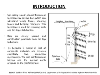
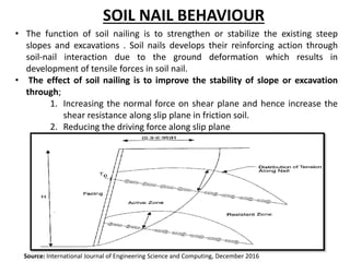
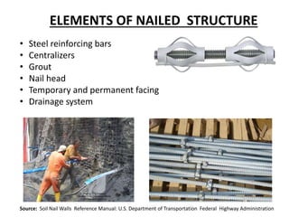
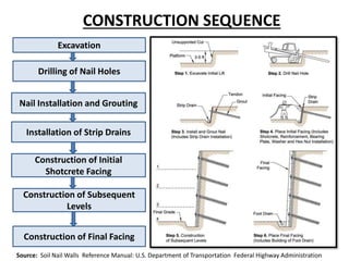
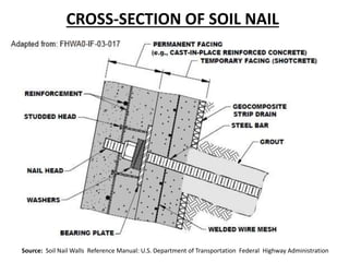
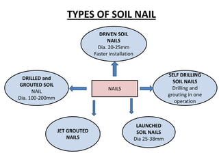
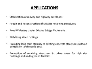
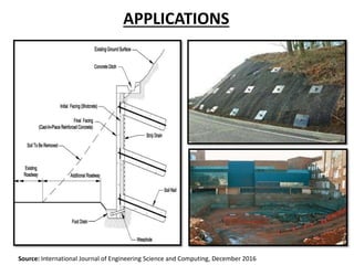
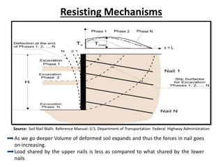
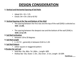
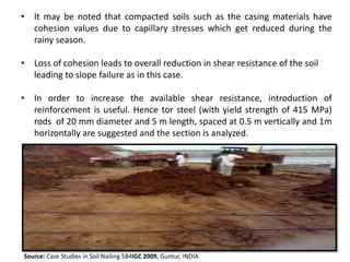
The document discusses the soil nailing technique for slope stabilization. Soil nailing involves installing reinforcing bars called nails into the slope using drilling and grouting. The nails strengthen the slope by increasing shear resistance along potential slip planes and reducing driving forces. Key elements of a nailed structure include steel nails, centralizers, grout, nail heads, and facings. Construction involves excavating and drilling nail holes before installing and grouting nails. Soil nailing is used to stabilize slopes, excavations, and retaining walls, offering advantages like rapid construction and flexibility. Design considerations include nail spacing, inclination, length, and pattern. A case study describes using soil nailing to stabilize an embankment slope at a reservoir.

![7.Maximum tensile forces
• In upper two third
• In lower one third value reduces to 50% of above.
8. Tensile force at wall facing
9. Pullout Resistance
q = nominal bond strength of the nail-grout-soil interface (force/unit area)
D= diameter of the drill hole
L= pullout development length
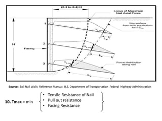
10.Nail Tensile Resistance
A = cross-sectional area of nail tendon
F = nominal yield resistance of nail tendon
Tmax = 0.50 Ka γs H SV SH to Tmax = 1.1 Ka γs H SV SH.
To= Tmax[0.6+.057(Smax-3)])]
Rp = πqDL
Rt = Af](https://image.slidesharecdn.com/soilnailing-181107171129/85/Soil-nailing-14-320.jpg)


![Soil Nailing (1) [Autosaved] (1).pptx](https://cdn.slidesharecdn.com/ss_thumbnails/soilnailing1autosaved1-221222041240-7deb4f00-thumbnail.jpg?width=640&height=640&fit=bounds)


