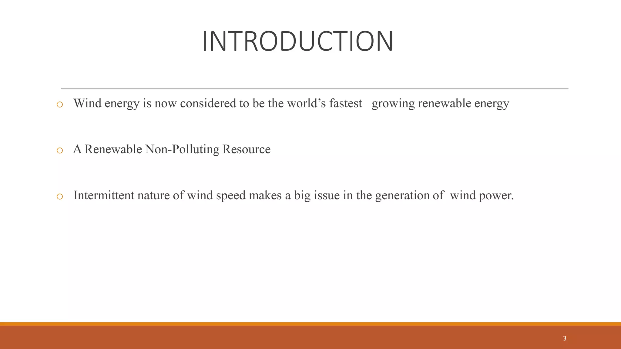
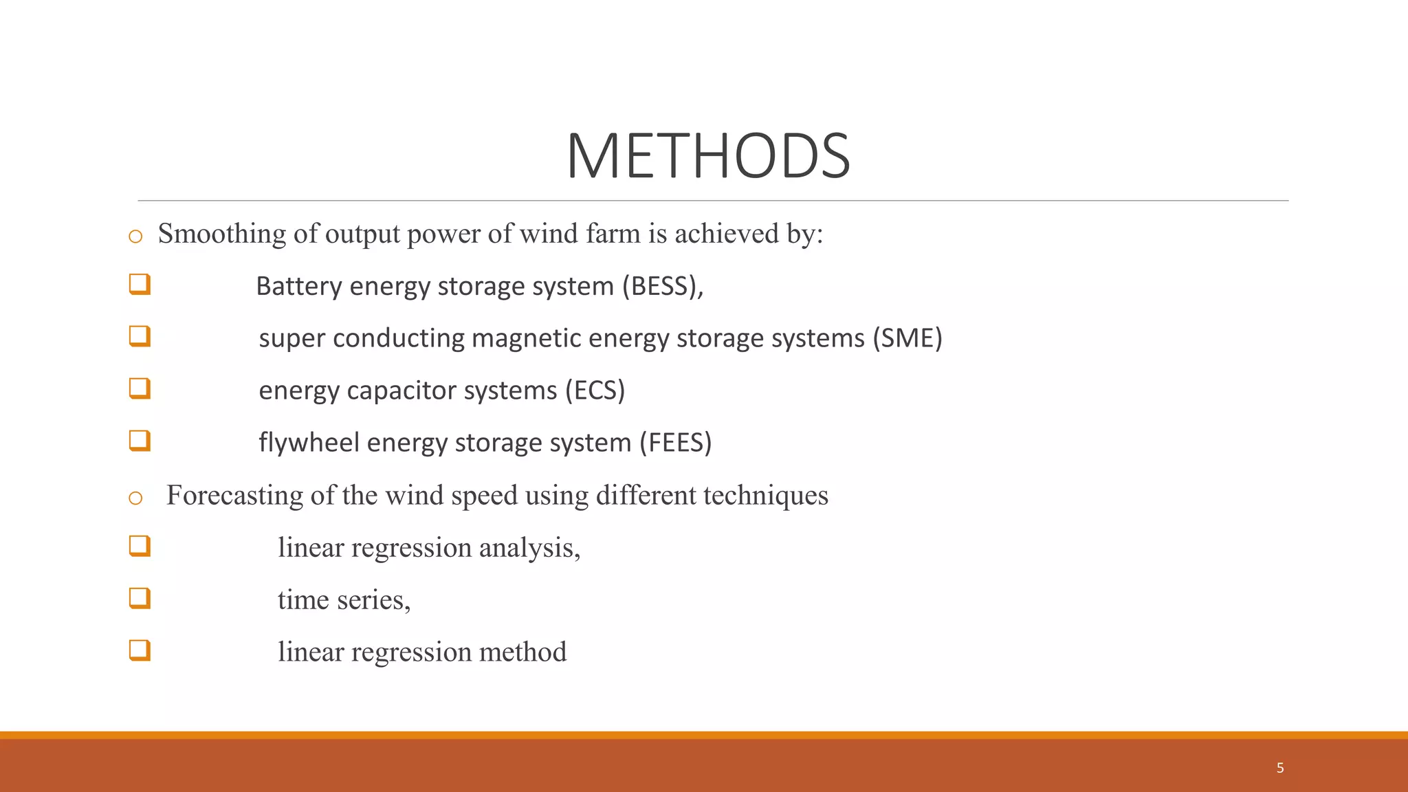
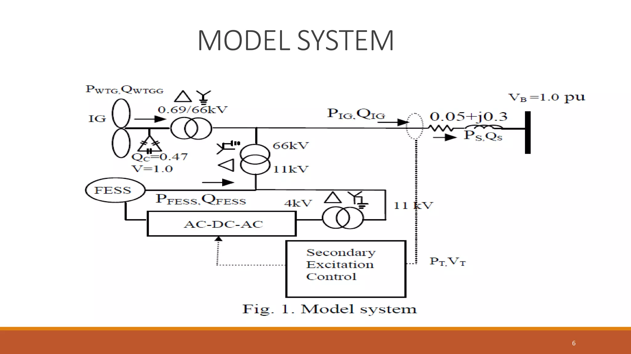
chaitra-1.pptx fake news detection using machine learning
Smoothing of Wind Farm Output using Short-Term ahead Wind Speed Prediction and Flywheel Energy Storage System
1. Smoothing of Wind Farm Output
using Short-Term ahead Wind Speed
Prediction and Flywheel Energy
Storage System
ROHITH PAUL
S7 F
ROLL NO: 46
1
2. CONTENTS
o INTRODUCTION
o NEED FOR SMOOTHING
o MODEL SYSTEM
o DIFFERENT MODELS OF SYSTEM
o SMOOTHING OF OUTPUT POWER
o WIND SPEED PREDICTION
o CONCLUSION
o REFRENCE
2
3. INTRODUCTION
o Wind energy is now considered to be the world’s fastest growing renewable energy
o A Renewable Non-Polluting Resource
o Intermittent nature of wind speed makes a big issue in the generation of wind power.
3
4. NEED FOR SMOOTHING
o Beneficial for power grid management
o Stabilization of power system
o Matching demand and supply
o To reduce frequency deviation in the grid
o Remove restrictions to install new wind farms.
4
5. METHODS
o Smoothing of output power of wind farm is achieved by:
Battery energy storage system (BESS),
super conducting magnetic energy storage systems (SME)
energy capacitor systems (ECS)
flywheel energy storage system (FEES)
o Forecasting of the wind speed using different techniques
linear regression analysis,
time series,
linear regression method
5
7. DIFFERENT MODELS OF SYSTEM
1. A. Wind Turbine model
2. Double Fed Induction Generator Model
3. FESS
4. Rotor Side Converter(RSC)
5. Grid Side Converter(GSC)
7
8. WIND TURBINE MODEL
o Consists of an Induction Generator and a wind turbine
o The reference power of the WF is adjusted according to the availability of the stored energy in
the FESS
o Wind turbines produce electricity by using the power of the wind to drive an electrical
generator
o Wind turbine extracts kinetic energy from the swept area of the blades
o Generated power is fed to the supply system when the IG is run above synchronous speed
o Generated power is 𝑃 𝑀=0.5∗ 𝜌 ∗ 𝐶 𝑃 ∗ 𝜋 ∗ 𝑅2 ∗ 𝑉 ∗ 𝑊3 ∗ 𝛼
8
9. DOUBLE FED INDUCTION GENERATOR
MODEL
o Modelled in the direct (d) and quadrature (q) axis reference frame,
FIG 2.
9
10. Contd…
o DFIG supplies the real power and it can compensate reactive power
o when rotor speed is greater than rotating magnetic field from stator, the stator induces a
strong current in the rotor
o power will be transferred as an electromagnetic force to the stator
o converted to electricity which is fed to the electric grid
10
11. ROTOR SIDE CONVERTER(RSC)
o Control the active and reactive power control of the stator side
o control the wind turbine output power and the voltage measured at the grid terminals
11
12. GRID SIDE CONVERTER(GSC)
o keep the DC link voltage constant at 1 p.u
o Supply additional reactive power into the grid
12
13. FESS
o DFIG with secondary excitation system is considered as FESS
o mechanical energy storage system where energy is stored in the form of kinetic energy.
o maximum and minimum energy that can be stored in the FESS is limited to ± 30% of
the rated energy
o The reference of the output power for the secondary excitation circuit is adjusted
according to the availability of the stored energy in FESS and predicted wind speed data.
13
16. Contd…
o reference output (P_ref_1) is generated using low pass filter function
o When the output of the IG is higher than the final output power reference, FESS is in
charging mode and absorbs the active power from the grid.
o when the generated output is lower than the final output power reference, FESS is in
discharging mode and supplies active power to the grid.
o By controlling the rotor speed of FESS in different operating regions, the stored energy in
FESS is utilized to smooth the output power fluctuation
16
17. WIND SPEED PREDICTION BY USING
LINEAR REGRESSION MODEL
o Wind speed data is predicted using short-term ahead linear regression model
o The prediction model has been implemented using MATLAB.
o Predicted power is given by:
𝑃𝑝𝑟𝑒𝑑𝑖𝑐𝑡𝑒𝑑=0.5∗ 𝜌 ∗ 𝐶 𝑃 ∗ 𝜋 ∗ 𝑅2
∗ 𝑉 ∗ 𝑉 ∗ 𝑉 ∗ 𝑊 ∗ 𝛼
17
18. Contd…
o If predicted power (P_Predict) - actual power (P_IG) is small output power reference remain
unchanged
o P_ref_2 is corrected if the actual stored energy of FESS is not in a range of (45-85)%
o this control scheme will prevent the system from reaching instability
18
20. Contd…
o Flowchart is used to modify the final output reference (P_ref_final)
o if the rotor speed of the FESS (W) is ≥1.3 p.u. or it is ≤ 0.7 p.u ,no power will be absorbed or
supplied by the FESS.
20
21. CONCLUSION
o Proposed a new control strategy of FESS to mitigate the fluctuation in the output power of the
grid
o It has been shown that prediction of the wind speed and modification of the output power
reference accordingly makes the FESS more effective and reduces the fluctuation of output
power efficiently.
o The system cost can also be kept minimum by optimum use of small capacity flywheel energy
storage system
21
22. REFRENCES
o “ A New Control Strategy for Smoothing of Wind Farm Output using Short-Term Ahead Wind Speed Prediction
and Flywheel Energy Storage System” Farzana Islam1, Hany. Hasanien2, Ahmed Al-Durra1, S.M.Muyeen1
o X. Wang, G. Siderators, N. Hatziargyrion and L. H. Tsoakalas, “Wind Speed Forecasting for Power System
Operational Planning,” International Conference on Probabilistic Methods applied to Power System, pp 470-474,
o S.M. Muyeen, M.H. Ali, R. Takahashi, T. Murata and J. Tamura,“Wind Generator Output Power Smoothing and
Terminal Voltage Regulation by Using STATCOM/ESS
22