Downloaded 110 times
![REFERENCES
[1]Jinsung Byun,Insung Hong,Byoungjoo Lee,Sehyun
Park, "Intelligent Household LED Lighting System
Considering Energy Efficiency and User
Satisfaction,” IEEE Trans. on Consumer
Electron.,Vol .59 , No.1, Feb.2013
[2] S. Matta and S. M. Mahmud, "An intelligent light
control system for power saving," in Proceedings of
the Annual Conference of the IEEE Industrial
Electronics Society, pp. 3316-3321, 2010
23](https://image.slidesharecdn.com/priya-160617114413/75/Energy-Efficient-Intelligent-LED-Lighting-System-25-2048.jpg)


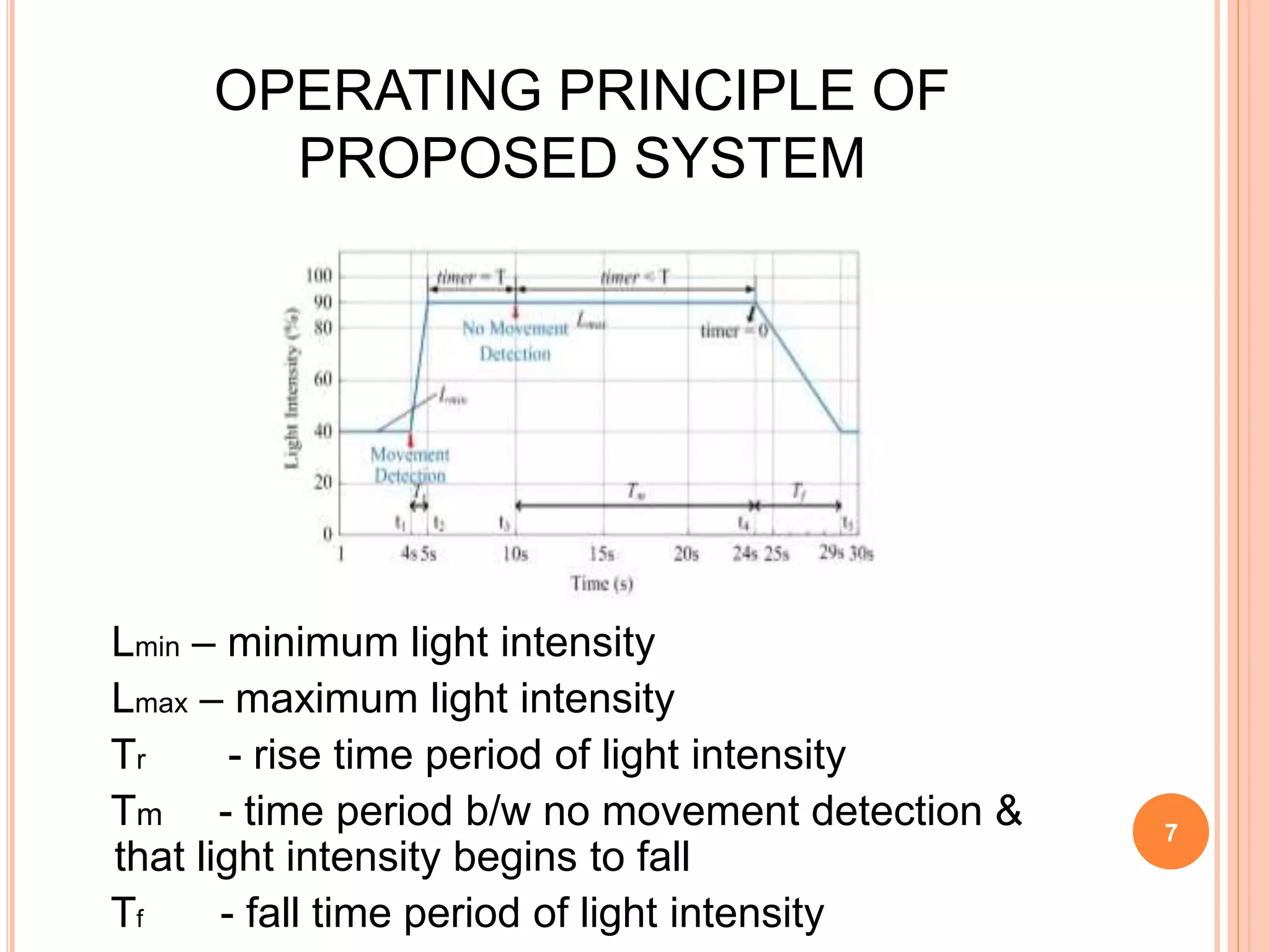
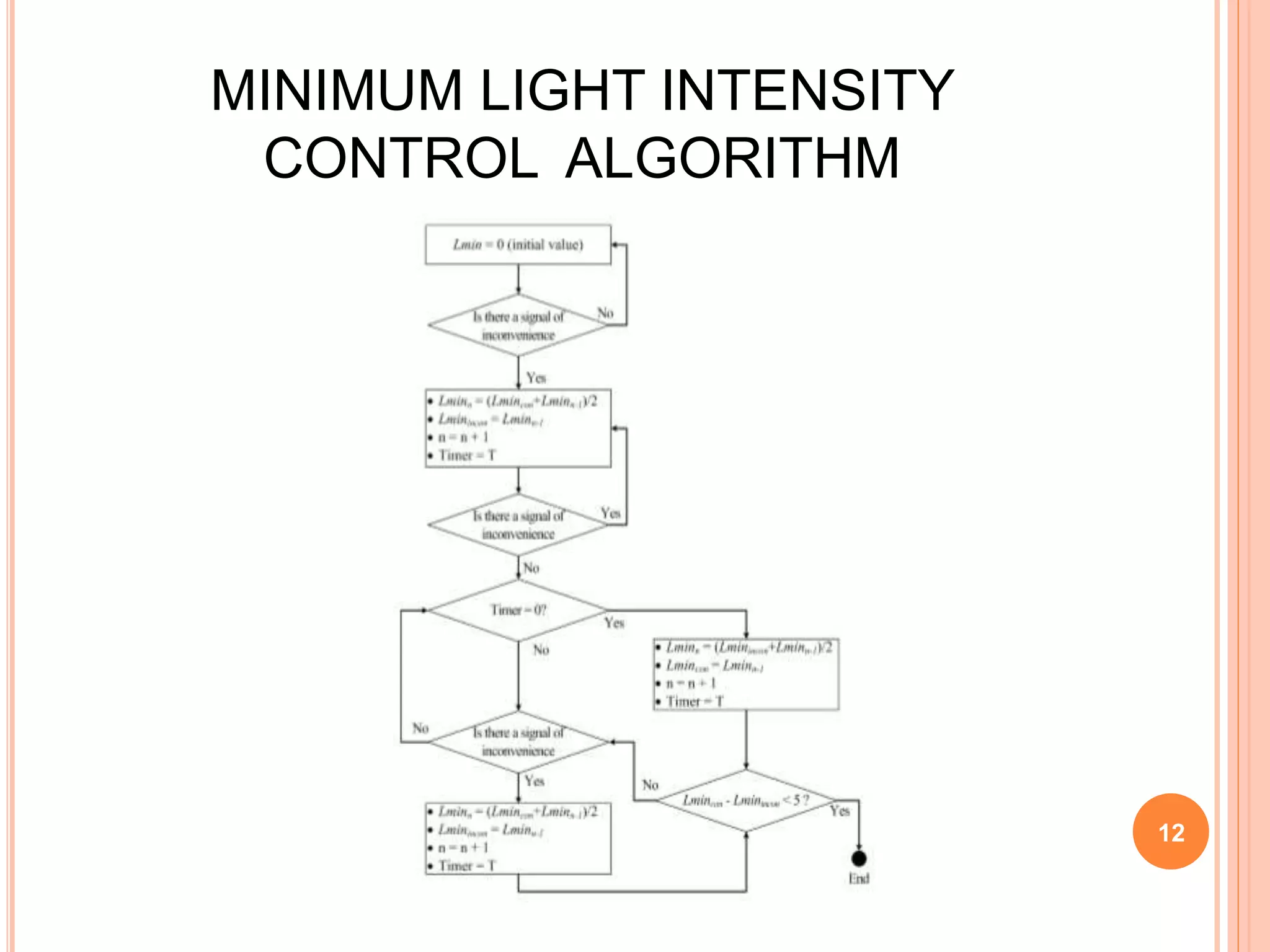
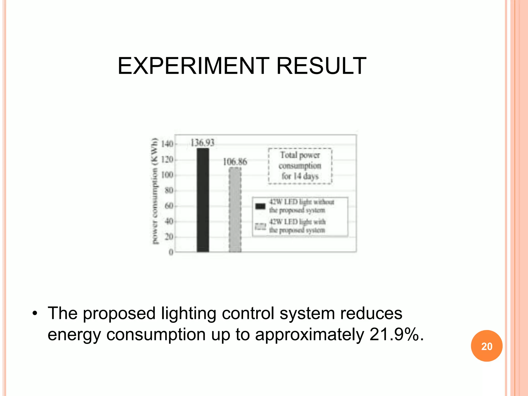
The document proposes an energy efficient intelligent LED lighting system that uses sensors and wireless communication to automatically control LED light intensity based on user presence and surroundings. The system aims to maximize energy savings while maintaining user satisfaction. It uses sensors to detect movement and light levels, and can adjust the minimum light intensity setting over time based on feedback from users through a mobile app. An experiment showed the system can reduce total energy consumption by up to 21.9% compared to traditional lighting.