Downloaded 858 times
![Smart Shopping System
Department of Computer Science and Engineering,JCE,Belagavi Page 1
Chapter 1
INTRODUCTION
1.1 OVERVIEW
According to present scenario, Now a day’s shopping at big malls is becoming a daily
activity in metro cities. The huge rush at malls on holidays and weekends. After purchase,
at the billing counter the cashier prepare the bill using bar code reader which is a time
consuming process and results in long queues..Considering all this ,we have
implemented a system that can be used in shopping malls to solve the rush at billing
counter using RFID based trolley.
1.2 INTRODUCTION
During the last decade the commercial use of RFID has been growing rapidly all
over the world. Furthermore, it is projected that the RFID market will reach an estimated
US$18.7 billion by the year 2017 (GIAI, 2012). Everywhere retailers are increasingly
embedding RFID technology into their supermarket products in order to improve the
customers’ shopping experience, customer support and develop new services for
customers.
RFID is a technology that uses radio waves to track, capture, identify and transfer
data efficiently and without human intervention. [2] RFID-based system gathers data
about a certain object without touching it or seeing it stag and forwards the information to
a host computer. The data on the tag include pointer to the central database within an
RFID system. RFID-Readers are able to establish a Channel of communication, read the
tags and trace the movement of these objects within the coverage area. RFID is a
promising technology which can improve operational efficiency specially a considerable
amount of reduction in transaction costs. Tag detection does not require human
intervention therefore reduces employment costs and eliminates human errors during data
collection. Due to its flexibility and business efficiency, the RFID technology has been
widely adopted in a wide range of applications such as supply chain management and
inventory, libraries, equipment and parts maintenance, vehicle identification, tracking
people, access control, reliable car tracking, manufacturing line control, automated](https://image.slidesharecdn.com/smartshoppingsystem-170703131526/85/Smart-shopping-system-1-320.jpg)
![Smart Shopping System
Department of Computer Science and Engineering,JCE,Belagavi Page 1
Chapter 1
INTRODUCTION
1.1 OVERVIEW
According to present scenario, Now a day’s shopping at big malls is becoming a daily
activity in metro cities. The huge rush at malls on holidays and weekends. After purchase,
at the billing counter the cashier prepare the bill using bar code reader which is a time
consuming process and results in long queues..Considering all this ,we have
implemented a system that can be used in shopping malls to solve the rush at billing
counter using RFID based trolley.
1.2 INTRODUCTION
During the last decade the commercial use of RFID has been growing rapidly all
over the world. Furthermore, it is projected that the RFID market will reach an estimated
US$18.7 billion by the year 2017 (GIAI, 2012). Everywhere retailers are increasingly
embedding RFID technology into their supermarket products in order to improve the
customers’ shopping experience, customer support and develop new services for
customers.
RFID is a technology that uses radio waves to track, capture, identify and transfer
data efficiently and without human intervention. [2] RFID-based system gathers data
about a certain object without touching it or seeing it stag and forwards the information to
a host computer. The data on the tag include pointer to the central database within an
RFID system. RFID-Readers are able to establish a Channel of communication, read the
tags and trace the movement of these objects within the coverage area. RFID is a
promising technology which can improve operational efficiency specially a considerable
amount of reduction in transaction costs. Tag detection does not require human
intervention therefore reduces employment costs and eliminates human errors during data
collection. Due to its flexibility and business efficiency, the RFID technology has been
widely adopted in a wide range of applications such as supply chain management and
inventory, libraries, equipment and parts maintenance, vehicle identification, tracking
people, access control, reliable car tracking, manufacturing line control, automated](https://image.slidesharecdn.com/smartshoppingsystem-170703131526/75/Smart-shopping-system-1-2048.jpg)
![Smart Shopping System
Department of Computer Science and Engineering,JCE,Belagavi Page 2
reading and receipt of goods at end sale points, e-passport and much more (Owunwanne
and Goel,2010). Implementation of RFID based applications has become an objective of
many Organizations, partially as a result of the decision made by Wal-Mart, the world’s
biggest retailer, to implement the RFID technology to monitor flow of pallets and
packaging in its supply chain and ask their top 100 vendors deploy RFID. The US
Department of Defence, Proctor and Gamble and the European retailer Metro Group
require their larger suppliers to implement RFID on every box and pallet shipped to them.
The grocery industry is a prime candidate for RFID implementation. On-hand shelf
inventory system in the supermarket will be linked to the store’s information system, thus
maintaining real time product information and automatic inventory tracking to keeping
the correct inventory levels. [2]Using RFID technology in supermarkets can also provide
detailed information on customer purchase behaviour. Currently most of the
supermarkets use a barcode-based system whereby an item is assigned a serial number
printed on the barcode label attached to an item and the item related information is stored
in the database of the back-end system. To perform inventory control, someone has to
scan the barcode label of each item and compare them with existing inventory list. This is
a lengthy and error prone process; as a result it’s done less frequently and hence often is
not up-to-date. The capabilities of the barcode technology are limited in term of
functionalities that businesses require (Bendavid et al.,2006). RFID technology offers a
solution to the above mentioned problem.
1.3 CHALLENGES OF THE PROPOSED SYSTEM
Some common problems with RFID are reader collision and tag collision. Reader
collision occurs when the signals from two or more readers overlap. The tag is unable to
respond to simultaneous queries. Systems must be carefully set up to avoid this problem.
Tag collision occurs when many tags are present in a small area; but since the read time is
very fast, it is easier for vendors to develop systems that ensure that tags respond one at
a time.
1.4 PROBLEM STATEMENT
An innovative product with societal acceptance is the one that aids the comfort,
convenience and efficiency in everyday life. Purchasing and shopping at big malls is
becoming daily activity in metro cities. There will be rush at these malls on holidays and
weekends. People purchase different items and put them in trolley. After completion of
purchases, one needs to go to billing counter for payments. At billing counter the cashier](https://image.slidesharecdn.com/smartshoppingsystem-170703131526/85/Smart-shopping-system-2-320.jpg)
![Smart Shopping System
Department of Computer Science and Engineering,JCE,Belagavi Page 3
prepare the bill using bar code reader which is very time consuming process and results
in long queue at billing counter.
In this Project, we are implementing a system “RFID Based Automatic Shopping
Cart” being developed to assist a person in everyday shopping in terms of reduced time
spent while purchasing. The main objective of proposed system is to provide a
technology oriented, low-cost, easily scalable, and rugged system for assisting shopping
in person.
1.5 PROPOSED SYSTEM
The main objective of proposed system is to provide a technology oriented, low-
cost, easily scalable, and rugged system for assisting shopping in person.[5] The RFID
powered electronic shopping cart is built to enhance the overall shopping experience for
electronics store consumers. Upon placing an item in the shopping cart, the consumer can
access an array of product information, advanced product specifications, product features,
consumer reviews, and combination deals with other store products. If a consumer is not
sure of the physical location of an item, they will be able to search for the item and view
a direct map of the store to find it. Other features include a live total of all items in the
cart, being able to view the weekly in-store specials and ready for pick up.
1.6 ORGANIZATION OF THE REPORT
Chapter 1 explains the overview, introduction, problem statement and proposed system.
Chapter 2 discusses about the literature survey about the existing system.
Chapter 3 gives the details of the requirement analysis and specification such as
functional, non-functional requirements, hardware and software requirements.
Chapter 4 explains the system design and implementation with the module description,
architecture diagram and data flow.
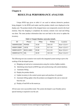
Chapter 5 discusses about the various System Testing..
Chapter 6 gives the results and detailed analysis of the results obtained.](https://image.slidesharecdn.com/smartshoppingsystem-170703131526/85/Smart-shopping-system-3-320.jpg)
![Smart Shopping System
Department of Computer Science and Engineering,JCE,Belagavi Page 4
Chapter 2
LITERATURE SURVEY
2.1 OVERVIEW
Literature Survey is an important phase in the system development life cycle as
we collect and acquire the necessary information to handle or develop a project during
this phase. A literature review is a description of the literature relevant to particular field
or topic. It gives an overview of what has been said, who the key writers are, what are the
prevailing theories and hypothesis and what methods and what methodologies are
appropriate and useful.
In this chapter research is done prior to taking up the project and understanding
the various methods that were used previously. A detailed analysis of the existing systems
was performed. This study helped to identify the benefits and drawbacks of the existing
systems.
Dr. Suryaprasad J in "A Novel Low-Cost Intelligent Shopping Cart“[1] proposed
to develop a low cost intelligent shopping aid that assists the customer to search and
select products and inform the customer on any special deals available on the products as
they move around in the shopping complex.
Amine Karmouche in "Aisle-level Scanning for Pervasive RFID-based Shopping
Applications" [2] proposed to develop a system that is able to scan dynamic and static
products in the shopping space using RFID Reader antennas. Instead of conducting the
RFID observations at the level of individual carts, aisle-level scanning is performed.
Mr. P. Chandrasekar in "Smart Shopping Cart with Automatic billing System
through RFID and ZigBee" [3] proposed to develop a shopping cart with a Product
Identification Device (PID) which will contain a microcontroller, a LCD, an RFID reader,
EEPROM, and ZigBee module. Purchasing product information will be read through a
RFID reader on shopping cart, meanwhile product information will be stored into
EEPROM attached to it and this EEPROM data will be send to Central Billing System
through ZigBee module. The central billing system gets the cart information and](https://image.slidesharecdn.com/smartshoppingsystem-170703131526/85/Smart-shopping-system-4-320.jpg)
![Smart Shopping System
Department of Computer Science and Engineering,JCE,Belagavi Page 5
EEPROM data, it access the product database and calculates the total amount of
purchasing for that particular cart.
Satish Kamble in "Developing a Multitasking Shopping Trolley Based on RFID
Technology" [4] proposed to develop a product to assist a person in everyday shopping in
terms of reduced time spent while purchasing. The main aim of proposed system is to
provide a technology oriented, low-cost, easily scalable, and rugged system for assisting
shopping in person.
Since this project itself is an application based on RFID Technology, we have
done a literature survey on some of the papers regarding our components and some
methodologies or techniques. In these papers we found the information required for our
project.
The paper has a generalised information to develop this project and even some of
the information about developing the communication between the devices that we use in
our project. The block diagram from the above paper is given bellow.
Fig.2.1 Generalized block diagram of Existing System.
From this block diagram we studied that they are using number of RFID readers
at the checkout points and in whole Super market to provide the network for updating the
cart information to the Back-end server. When the customer starts shopping and starts](https://image.slidesharecdn.com/smartshoppingsystem-170703131526/85/Smart-shopping-system-5-320.jpg)
![Smart Shopping System
Department of Computer Science and Engineering,JCE,Belagavi Page 6
collecting the items to purchase, the cart will communicate with RFID reader nearer to it
and updates the carts information. But by doing so the complexity is increased in
hardware and as well as detecting the tags.
To collect information about single cart is easy but if the number of carts
increased then it will be very difficult to collect information about all the carts
simultaneously. Since they are using RFID only for both reading the tags and sending the
information to the server from the cart. This will create a huge disturbance
2.2 NEED OF ZIGBEE
Zigbee is a wireless communication technology which supports for multi-node
communication. This will help us to prevent the Data interference while collecting the
data from the cart to the server. [3]Here it can even reduce the amount of Hardware
required and complexity in information collection. By this the system will become
cheaper. Even though the cost required for the individual components is high, but cost
will become less for huge production.
Table 2.1Difference between Existing system and Proposed system
EXISTING SYSTEM PROPOSED SYSTEM
1. Manual billing 1.Automatic billing
2. Use Barcode for billing 2.Use RFID TAG for billing
3. Human staff is needed for billing 3.No need of any staff for billing
4. Low product cost but over all
expenses are much high.
4.Product is little expensive but
over all expense is much low
5. Difficult to track the product 5.Easy to locate or track the product
6. Getting product information is
difficult & time consuming
6. Getting product information is
easy and no extra time needed
7. It does not disclose any automatic
way of indicating to shopper how
the total bill is affected as the
objects are added or removed from
7.LCD Display is present which
will show the updated bill every
time the shopper add or remove any
object from the cart.](https://image.slidesharecdn.com/smartshoppingsystem-170703131526/85/Smart-shopping-system-6-320.jpg)
![Smart Shopping System
Department of Computer Science and Engineering,JCE,Belagavi Page 9
3.4 HARDWARE REQUIREMENT
3.4.1 RFID tag
An RFID tag is comprised of a microchip containing identifying information and
an antenna that transmits this data wirelessly to a reader. At its most basic, the chip will
contain a serialized identifier, or license plate number, that uniquely identifies that item,
similar to the way many bar codes are used today. A key difference, however is that [2]
RFID tags have a higher data capacity than their bar code counterparts. This increases the
options for the type of information that can be encoded on the tag, including the
manufacturer, batch or lot number, weight, ownership, destination and history (such as
the temperature range to which an item has been exposed). In fact, an unlimited list of
other types of information can be stored on RFID tags, depending on application needs.
An RFID tag can be placed on individual items, cases or pallets for identification
purposes, as well as on fixed assets such as trailers, containers, totes, etc.
Fig 3.4.1 RFID TAGS
Passive versus Active
“Passive” tags have no battery and "broadcast" their data only when energized by
a reader. That means they must be actively polled to send information. "Active" tags are
capable of broadcasting their data using their own battery power. In general, this means
that the read ranges are much greater for active tags than they are for passive tags perhaps
a read range of 100 feet or more, versus 15 feet or less for most passive tags. The extra
capability and read ranges of active tags, however, come with a cost; they are several
times more expensive than passive tags. Today, active tags are much more likely to be](https://image.slidesharecdn.com/smartshoppingsystem-170703131526/85/Smart-shopping-system-9-320.jpg)
![Smart Shopping System
Department of Computer Science and Engineering,JCE,Belagavi Page 10
used for high-value items or fixed assets such as trailers, where the cost is minimal
compared to item value, and very long read ranges are required. Most traditional supply
chain applications, such as the RFID-based tracking and compliance programs emerging
in the consumer goods retail chain, will use the less expensive passive tags.
3.4.2 RFID reader
RFID reader is used to read the data’s present in the RFID tag. RFID readers or
receivers are composed of a radio frequency module, a control unit and an antenna to
interrogate electronic tags via radio frequency (RF) communication. Many also include
an interface that communicates with an application. Readers can be hand-held or mounted
in strategic locations so as to ensure they are able to read the tags as the tags pass through
an “interrogation zone.”
Fig 3.4.2 RFID reader.
An RFID reader’s function is to interrogate RFID tags. The means of
interrogation is wireless and because the distance is relatively short; line of sight between
the reader and tags is not necessary.[2] A reader contains an RF module, which acts as
both a transmitter and receiver of radio frequency signals. The transmitter consists of an
oscillator to create the carrier frequency; a modulator to impinge data commands upon
this carrier signal and an amplifier to boost the signal enough to awaken the tag. The
receiver has a demodulator to extract the returned data and also contains an amplifier to
strengthen the signal for processing. A microprocessor forms the control unit, which](https://image.slidesharecdn.com/smartshoppingsystem-170703131526/85/Smart-shopping-system-10-320.jpg)

![Smart Shopping System
Department of Computer Science and Engineering,JCE,Belagavi Page 20
Working
The module has simple Protocol for working. the Using ilabs CC transreceiver GUI, the
module can be configured data communication through hyper terminal. [3] This modules
basically take TTL data & send it to receiver(receiver whose ID is send along with data).
Modules can also broadcast the data (broadcast id (0xff).A single module can
communicate with number of modules at run time. as receiver ID needs to send every
time, So one can send different receiver id every time to communicate with different
modules. This feature makes it best suited for swarm robotics.
As modules has capability of analog to digital conversion (ADC). So user has to
just configure the module once for ADC, & the module will send the data to the
respective receiver, at the given interval of time. This feature (of reading ADC value &
sending to the respective receiver module) makes it standalone for WSN. So it reduces
the need of separate controller. The GUI interface makes it easy for user to configure
module as well as to send data & test modules for different settings.
PIN CONNECTIONS
Ilabs CC2500 transreceiver module is having 3 connector headers (P1, P2 & P3as
shown in picture). P1 is having 4 pins GND (V-), VCC (V+), Rx, Tx. Where Jumper 2 is
having 6 pins A0 to A5 (ADC 0 to ADC 5).
Fig3.4.7(b) Pin diagram of ZIGBEE.
Configuring ilabs CC2500 Module
Ilabs cc2500 module can configure for various things like Self ID (self address or
SID), Channel ID (CID), Baud Rate (max 38400bps) and ADC values.](https://image.slidesharecdn.com/smartshoppingsystem-170703131526/85/Smart-shopping-system-20-320.jpg)

![Smart Shopping System
Department of Computer Science and Engineering,JCE,Belagavi Page 24
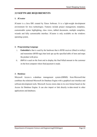
The model features a cart equipped with an RFID reader, a ZigBee transceiver
and an LCD display[5]. The cart is initially deactivated. Upon entering in the specific
area, the store’s main reader would trigger the respective passive RFID tag on the cart
that entered, thus activating it, and turning ON all the components such as RFID reader,
micro controller and ZigBee The reader on the cart sends the tagID of the item being
dropped into or removed from the cart and price against it to the main reader which
updates the bill for the respective cart. It scans products when customer picks up from the
shelf and puts in the cart. The cartID, tagID of the item and the corresponding price is
transmitted by the cart’s reader to the main reader using the IEEE 802.15.4 (ZigBee
Protocol). This smart shopping cart keeps an account of the bill made by keeping running
total of their purchases. LCD screen will show the total bill of the items present in the
cart.
The main reader is consistently connected with the database via server and is
equipped with ZigBee transceiver to receive from the cart’s reader cartID, tagID and
price of the data item which is being put into or removed from the cart. This main reader
is also in communication with reader on the exit door which detects a particular cart at
the checkout time. This exit door reader has a ZigBee transceiver so as to send the
information of detected cart to the main reader . It also communicates with the server via
the main reader, which is being constantly updated by the main reader for every cart that
entered the store area. The server is connected to the database. All the changes intended
to be made in the database are made with help of the server via main reader
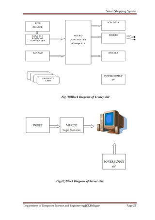
Fig (A) Smart Trolley](https://image.slidesharecdn.com/smartshoppingsystem-170703131526/85/Smart-shopping-system-24-320.jpg)
![Smart Shopping System
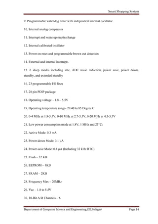
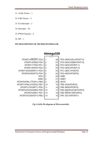
Department of Computer Science and Engineering,JCE,Belagavi Page 26
Figure A, B and C depicts a block diagram containing the subsystems of
intelligent trolley. Each subsystem is interfaced carefully to form a whole unit. This
system consists of a micro controller interfaced with RFID, ZigBee, RFID Tags, LCD
20x4 display, forming the hardware unit and ZigBee interfaced to the server making up
the software unit. When any product containing RFID tag is placed in the trolley, it is
detected and information is collected. The RFID tags have a unique ID number. RFID
tags are used to uniquely identify products. This information is then sent to the main
server using the wireless ZigBee unit. The data sent is the unique number. At the server
end, the database is queried based on the unique number. All the products and their
respective details stored in that particular database are retrieved and sent back to the
shopping trolley. The information received from the server is temporarily stored in the
shopping trolley memory and then displayed on the display unit affixed on the trolley.
The customer can then select the product with the information being shown on the display
unit. Every product is uniquely identified using RFID tags. As the products are selected
and added into the cart, the RFID reader will identify the product and the price will be
added to the temporary bill. If a customer chooses to drop a selected product, it needs to
be done by selecting the appropriate button (“Add/Remove”) on the display unit. After
completing the shopping, the customer has to select the “Complete” button. This enables
the total bill being generated after confirmed purchase of all the selected products in the
shopping trolley. This generated bill is sent to billing side computer to get the
computerized bill. At the same time, this information is sent to the database server
through the wireless ZigBee unit. The integrated system is built around AT89S52 micro
controller and 20x4 LCD display unit and miscellaneous circuit including power supply.
4.1 RFID (RADIO FREQUENCY IDENTIFICATION)
RFID (radiofrequency identification) technology offers the ability to provide
many new services and convenience in the retail environment. Radio-frequency
identification (RFID) is an automatic identification method, relying on storing and
remotely retrieving data using devices called RFID tags or transponders. [2]The
technology requires some extent of cooperation of an RFID reader and an RFID tag. An
RFID tag is an object that can be applied to or incorporated into a product, animal, or
person for the purpose of identification and tracking using radio waves. Some tags can be
read from several meters away and beyond the line of sight of the reader](https://image.slidesharecdn.com/smartshoppingsystem-170703131526/85/Smart-shopping-system-26-320.jpg)
![Smart Shopping System
Department of Computer Science and Engineering,JCE,Belagavi Page 45
REFERENCES
[1] Dr. Suryaprasad J, Praveen Kumar B O, Roopa D & Arjun A K "A Novel Low-Cost
......Intelligent Shopping Cart", 2014 IEEE.
[2] Amine Karmouche, Yassine Salih-Alj, "Aisle-level Scanning for Pervasive RFID-
......based Shopping Applications", 2013 IEEE.
[3] Mr. P. Chandrasekar, Ms. T. Sangeetha, "Smart Shopping Cart with Automatic Central
......Billing System through RFID and ZigBee", 2014 IEEE.
[4] Satish Kamble, Sachin Meshram, Rahul Thokal & Roshan Gakre, "Developing a
......Multitasking Shopping Trolley based on RFID Technology", January 2014
......International Journal of Soft Computing and Engineering (IJSCE).
[5] Raju Kumar, K. Gopalakrishna, K. Ramesha,"Intelligent Shopping Cart" International
.....Journal of Engineering Science and Innovative Technology (IJESIT) Volume 2, Issue
.....4, July 2013.
[6] Janhavi Iyer, Harshad Dhabu, Sudeep K. Mohanty, "Smart Trolley System for
......Automated Billing using RFID and ZIGBEE" International Journal of Emerging
......Technology and Advanced Engineering Volume 5, Issue 10, October 2015.](https://image.slidesharecdn.com/smartshoppingsystem-170703131526/85/Smart-shopping-system-45-320.jpg)

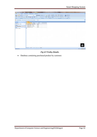
The document outlines a proposed RFID-based automatic shopping cart system designed to enhance the shopping experience by reducing time spent at billing counters in malls. It explains the advantages of RFID technology over traditional barcode systems, such as eliminating the need for human intervention and improving operational efficiency. The system aims to be low-cost, easily scalable, and user-friendly while addressing challenges related to signal interference in dense environments.


