Download to read offline
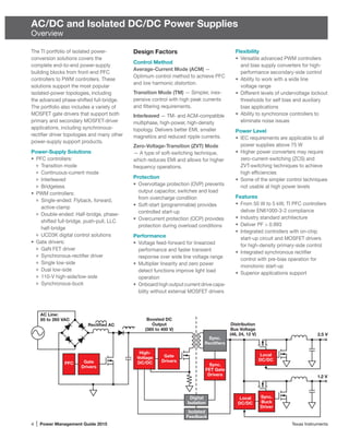
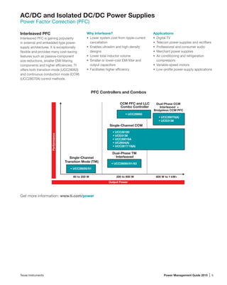
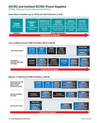
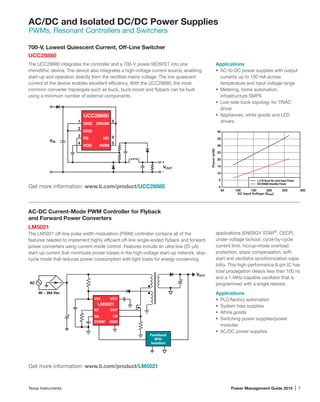
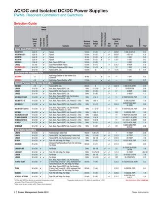
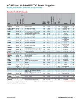
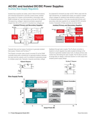
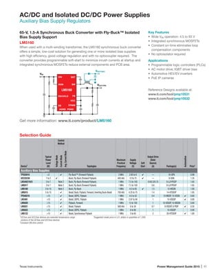
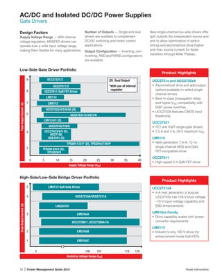

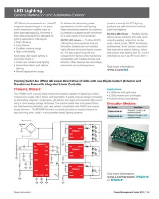
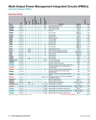
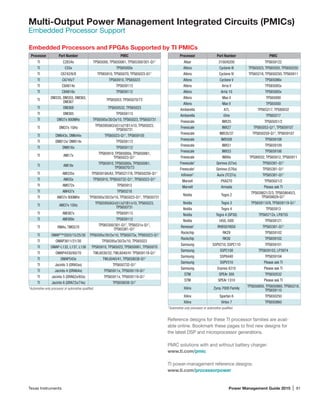
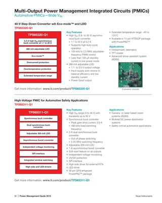
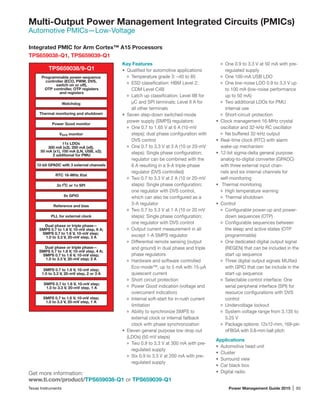
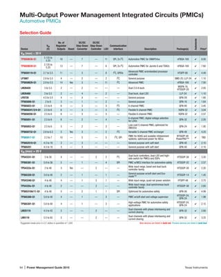
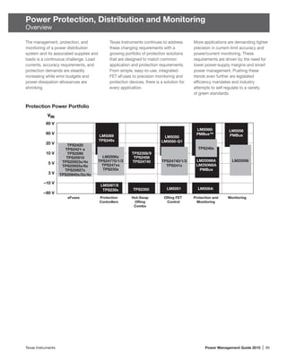
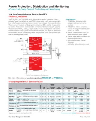
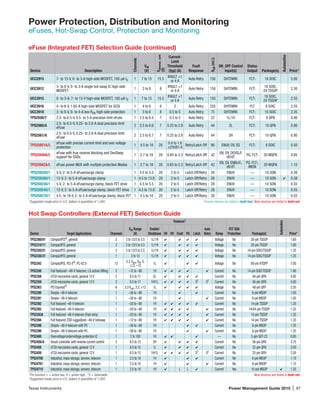
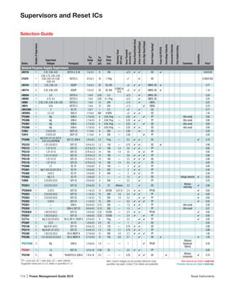
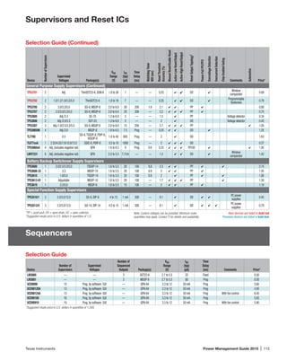
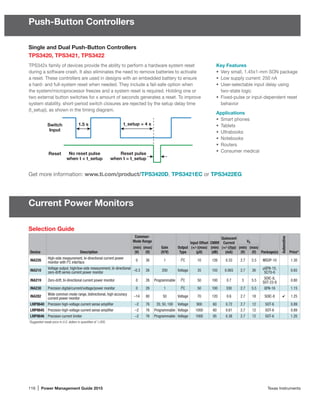
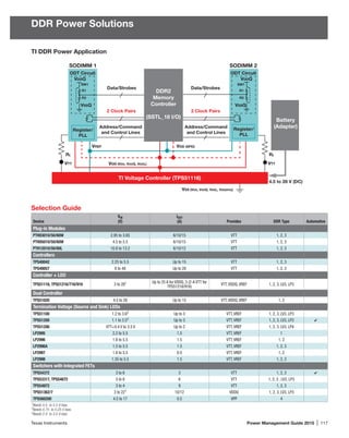

The document provides an overview and selection guide for Texas Instruments' portfolio of isolated AC/DC and DC/DC power supply solutions. It describes various power factor correction, PWM, and isolated DC/DC controller and switcher ICs covering applications from 50W to multi-kilowatt power levels. Design considerations and featured products are highlighted for PFC controllers, PWM controllers, resonant controllers, switchers, and other isolated power solutions.


