This document compares the design of RC slab culverts using the working stress method specified in IRC 21:2000 and the limit state method specified in IRC 112:2011. It analyzes slab culvert spans from 4m to 10m with different L/d ratios for both methods. For the working stress method, an L/d ratio of 13 is found to be optimal. For the limit state method, L/d ratios of 18-20 satisfy design checks but 20 is most economical. The limit state method can save up to 30-35% concrete compared to the working stress method. L/d ratio of 20 under limit state design provides better utilization of limiting moment capacity and satisfies serviceability criteria like deflection and crack
![Comparative Study of Slab Culvert Design using IRC 112:2011 and IRC 21:2000
(IJSRD/Vol. 3/Issue 05/2015/026)
All rights reserved by www.ijsrd.com 108
Finally calculation of area of steel is done by using working
stress method formulas.
5) Calculation of shear stresses
Maximum shear force occurs at the support when the live
load is nearer to a support. Here the design shear is
conservatively taken as that at the support.
Calculation of effective length of dispersion
Calculation of effective width of dispersion
Fig. 4 Position of load for maximum shear
Nominal shear stress = Ʈ = Vu/ bd
k1 = 1.14 -0.7d
k2 = 0.5+ 0.25 ρ where ρ =
Ʈc = permissible shear stress = k1 k2 Ʈco
B. Limit State Method
Calculation of Bending Moments and Shear forces remains
same as per working stress method except 1.5 is multiplied
for final design moments and design shear forces. In this
design moment is checked with limiting moment of
resistance and finally area of steel is calculated using design
bending moment.
1) Design shear reinforcement is calculated as per
I.R.C:112-2011 (clause 10.3.2)
V Rdc = [0.12 K (80 ρ1 fck) 0.33
+ 0.15 ϭcp] bwd
K = 1 + √ ≤ 2.0
ϭcpis limited to 0.2fcd
ρ1 = As1/bwd ≤ 0.02
2) Checks for limit state of serviceability:
Check for Limit State of Deflection:
∆ = ]
W = average intensity
L = Effective length of span
a = Load Effective length
E = Young’s Modulus of concrete = 5000√
I = Moment of Inertia =
Check for limit state of crack width:
Fig. 5: Cross section and strain diagram
Calculation of B.M at service load, Ms
Ec = 5000√ = 5000√ = 25000 N/mm2
Ece = 0.5Ec
M = Es/ Ece
Determination of N.A at working loads
m Ast(d-x)
Ic = + m Ast (d-x)2
Є1 =
Єm = Є1 –
( ) ( )
( )
Crack width = 3 Cmin Єm
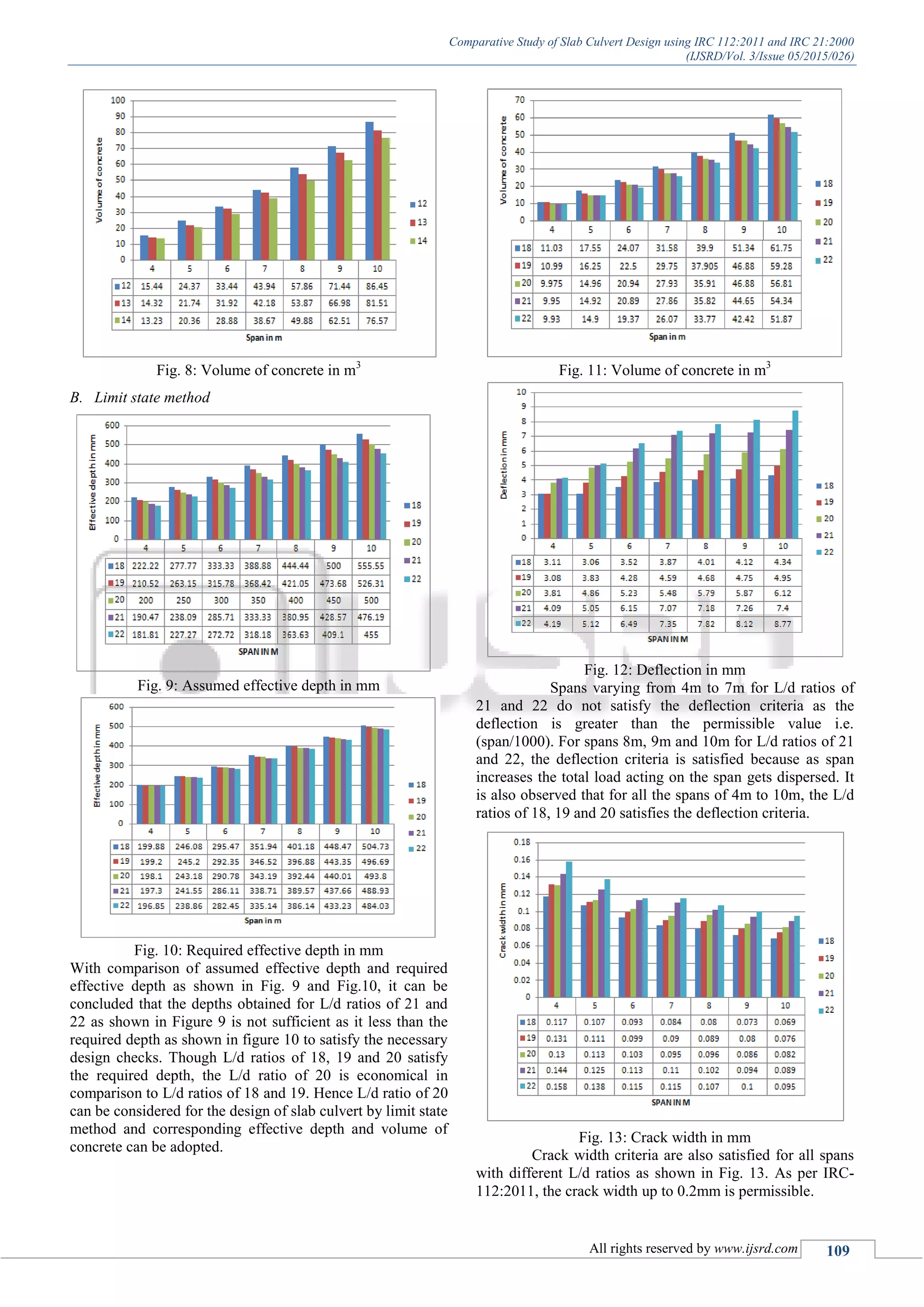
III. RESULTS AND DISCUSSIONS
The slab culvert of span 4m to 10m is analysed for various
IRC loadings as per IRC 21-2000 by working stress method
for L/d ratios 12, 13 and 14 and same spans are analysed as
per IRC 112-2011 by limit state method for L/d ratios 18,
19, 20, 21 and 22. The critical case for loading is tracked
vehicle as compared to wheeled and trained vehicle and
hence taken for all the calculations in arriving effective
depth and bending moment.
A. Working Stress Method
Fig. 6: Assumed effective depth in mm
Fig. 7: Required effective depth in mm
With comparison of assumed effective depth and
required effective depth as shown in Fig. 6 and Fig. 7, it can
be concluded that the depths obtained for L/d ratio of 14 as
shown in figure 6 is not sufficient as it less than the required
depth as shown in figure 7 to satisfy the necessary design
checks.
Though L/d ratios of 12 and 13 satisfy the required
depth, the L/d ratio of 13 is economical in comparison to
L/d ratio of 12. Hence L/d ratio of 13 is preferable for the
design of slab culvert by working stress method and
corresponding effective depth and volume of concrete can
be adopted.](https://image.slidesharecdn.com/slabculvertirc21irc112-200515021229/75/Slabculvert-irc21irc112-3-2048.jpg)
![Comparative Study of Slab Culvert Design using IRC 112:2011 and IRC 21:2000
(IJSRD/Vol. 3/Issue 05/2015/026)
All rights reserved by www.ijsrd.com 110
Fig. 14: Variation of maximum bending moment
Fig. 15: Variation of limiting moment of resistance
In Figures 14 and 15 for L/d ratios of 18 and 19,
there is a less limiting moment utilization capacity in
comparison to L/d ratio of 20. For shorter spans with L/d
ratios of 21 and 22, the limiting moment is less than the
maximum bending moment. Hence L/d ratio 20 can be
considered for safe and economical design of slab culvert by
limit state method.
IV. CONCLUSIONS
1) For design of the slab culvert using working stress
method as per IRC: 21-2000, L/d ratio of 11 to 13 can
be adopted, L/d ratio of 13 is most preferable.
2) For design of the slab culvert using limit state method
as per IRC: 112-2011, L/d ratio of 18 to 20 can be
adopted, L/d ratio of 20 is most preferable.
3) Increase in effective depth with increase in span is
found to be lesser for L/d ratio of 20 when compared to
L/d ratio of 18 and 19. As thickness of slab increases,
the volume of concrete increases and hence dead load
increases.
4) Deflections are within the limiting value as mentioned
in IRC: 112-2011 but this is not a case for L/d ratio
higher than 20.
5) It is observed that in slab culvert for L/d ratio of 20, the
quantity of concrete saved is up to 30 to 35% using
limit state method.
6) In limit state method of design the utilization capacity
of limiting moment will increase with increasing span
which is up to 65%. It is observed that the utilization
capacity for L/d ratio of 18 & 19 is lesser and for L/d
ratio of 21 and 22 it is found to be higher when
compared to L/d ratio of 20.
ACKNOWLEDGEMENTS
The author wishes to thank the Management and Principal
of KLS Gogte Institute of Technology, Belagavi, Karnataka,
India for their continued support in carrying out this
research work.
REFERENCES
[1] “Design of Bridges” by Krishnaraju, Fourth Edition,
Oxford and IBH Publishing Co. Pvt. Ltd., New Delhi,
India, 2012. Page No 86-159.
[2] IRC: 6-2000, “Standard Specifications and Code of
Practice for Road Bridges”, Section II, loads and
stresses, The Indian Roads Congress, New Delhi, India,
2000.
[3] Solanki B.H. and Vakil M.D., “Comparative study for
flexure design using IRC 112:2011 & IRC 21:2000”
International journal of scientific and engineering
research Vol.4 issue-6 june-2013.
[4] Solanki B.H. and Vakil M.D., “Comparative study for
shear design using IRC 112:2011 & IRC 21:2000”
International journal of scientific and engineering
research Vol.4 issue-6 june-2013.
[5] IRC: 21 –2000 “Standard specification and code of
practice for road bridges (Plain and Reinforced)” Indian
road congress, New Delhi, India, 2000.
[6] IRC: 18 –2000 “Standard specification and code of
practice for road bridges (Plain and Reinforced)” Indian
road congress, New Delhi, India.
View publication statsView publication stats](https://image.slidesharecdn.com/slabculvertirc21irc112-200515021229/75/Slabculvert-irc21irc112-5-2048.jpg)


