Download to read offline
![International Research Journal of Engineering and Technology (IRJET) e-ISSN: 2395 -0056
Volume: 04 Issue: 06 | June -2017 www.irjet.net p-ISSN: 2395-0072
© 2017, IRJET | Impact Factor value: 5.181 | ISO 9001:2008 Certified Journal | Page 1044
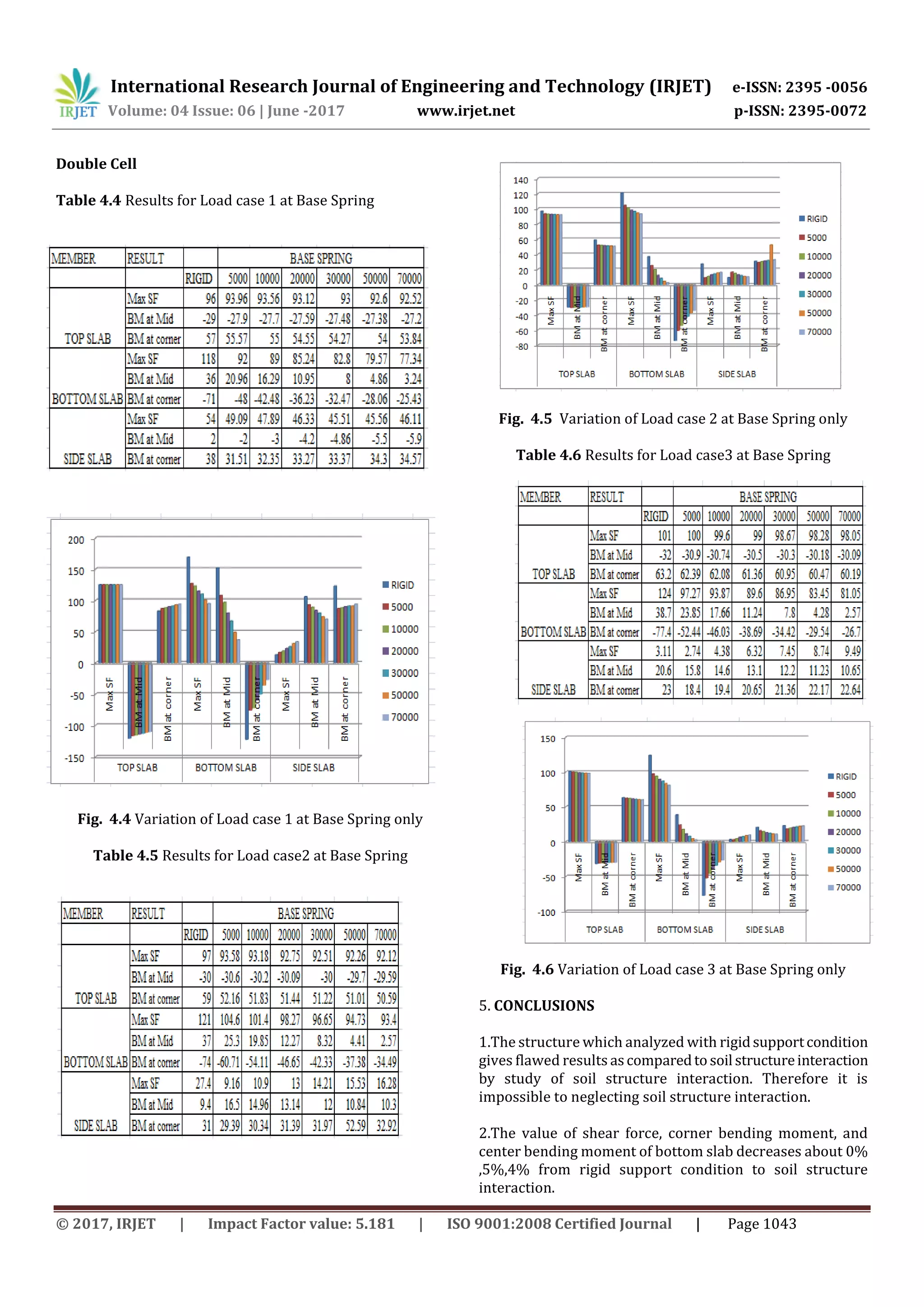
3.The value of SF, corner BM, and center BM of bottom slab
decreases about 24%, 30%, 30% from rigid support to soil
structure interaction
4.The value of SF, corner BM, and center BM of side wall
decreases about 20%, 30%, 13% from rigid support to soil
structure interaction.
5. For load combination 3 (Dead load+ earth pressure+
water pressure ) SF and BM gives considerably results as
compared to other load combination.
6.There for SF and BM values are lesser with soil structure
interaction .
6. REFERENCES
[1] Mohankar.R.H,Ronghe.G.N, _Analysis and Design of
Underpass RCC Bridge International Journal Of Civil And
Structural Engineering Volume 1, No 3, 2010
[2]VinayakDemane,“Soilstructure interaction of underpass
R.C.C Bridge” International journal of engineering research
and technology (IJERT) volume1 issue 4 2013 ISSN (e):
2321-3418.
[3] Mr. Afzal Hanif Sharif, “Review paper on analysis and
design of railway box bridge” Volume 1, Issue 7, july 2016
JSDR ,ISSN:2455-2631.
[4] D.Vamshee Krishna, “ RCC underpass Design, Modeling
and Analysis using Parametric study of soil structure
interactions” International Journal of Advance Research,
IJOAR .org Volume 3, Issue 8, August 2015, Online: ISSN
2320-9100.
[5] Dr. B.C. Punmia, “RCC Designs” (Reinforced concrete
Structures)
[7]N.KrishnaRaju,“Design of Bridges”(2009), Oxford & IBH
publishing Pvt. Ltd. New Delhi.
[8]IRC: 21:2000, “Standard Specifications And Code Of
Practice Road Bridges” The Indian Road Congress.
[9] IRC: 6:2000, “Standard Specifications And Code Of
Practice Road Bridges” TheIndian Road Congress.](https://image.slidesharecdn.com/irjet-v4i6193-180129093330/75/Assessment-of-Soil-Structure-Interaction-on-RCC-Underpass-Bridge-5-2048.jpg)

This document analyzes the soil-structure interaction of reinforced concrete underpass bridges. It presents a case study of single cell and double cell underpass bridge models analyzed using finite element software. Three foundation conditions are considered: rigid supports, springs at the base only, and springs at the base and sidewalls. Results for bending moment, shear force, and axial thrust are presented for different load combinations and subgrade modulus values. The study found that accounting for soil-structure interaction reduces stresses in the structure compared to assuming rigid supports. Stresses were lowest for the load combination of dead load, earth pressure, and water pressure.


