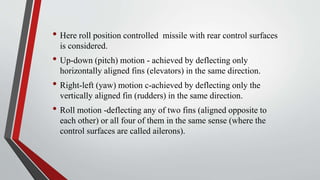
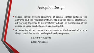
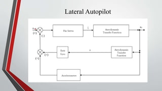
- Guided missiles use autopilots and control surfaces like elevators and rudders to adjust their trajectory in flight. Autopilots help control the missile's roll, pitch, and yaw motions.
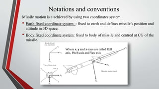
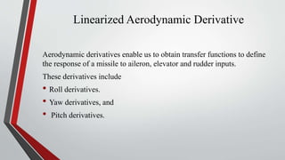
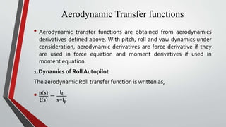
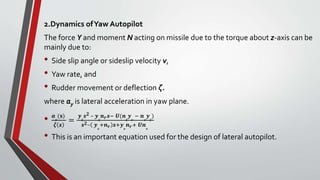
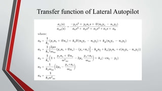
- Aerodynamic derivatives describe the missile's response to control surface deflections, and are used to develop transfer functions for the roll, pitch, and yaw autopilots.
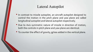
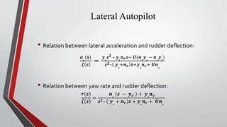
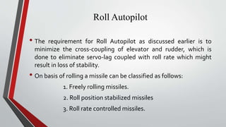
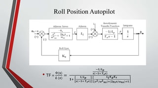
- Lateral and roll autopilots are designed to control motion in the yaw and roll planes respectively. The lateral autopilot relates lateral acceleration and yaw rate to rudder deflection using aerodynamic derivatives. The roll autopilot minimizes cross-coupling between controls.