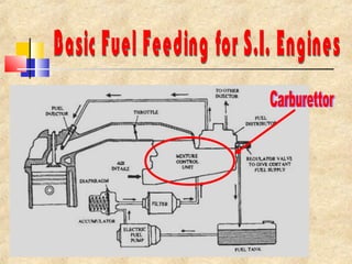
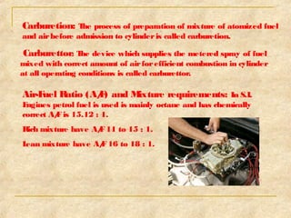
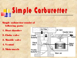
By, 
Parikshit Purandare 
S.E. Mechanical Engg 
VACOE, Ahmednagar
Carburetion: The process of preparation of mixture of atomized fuel 
and air before admission to cylinder is called carburetion. 
Carburettor: The device which supplies the metered spray of fuel 
mixed with correct amount of air for efficient combustion in cylinder 
at all operating conditions is called carburettor. 
Air-Fuel Ratio (A/F) and Mixture requirements: In S.I. 
Engines petrol fuel is used is mainly octane and has chemically 
correct A/F is 15.12 : 1. 
Rich mixture have A/F 11 to 15 : 1. 
Lean mixture have A/F 16 to 18 : 1.
Speed 
Temperature of inlet air 
Volatility of fuel 
Design of intake manifolds
Simple carburettor consist of 
following parts: 
1. Float chamber 
2. Choke valve 
3. Throttle valve 
4. Venturi 
5.Main nozzle
1. Starting Choke: At the time of starting of engine rich mixture should 
be provided during cold conditions and it is achieved by butterfly valve 
called choke. 
2. Main metering and Idling System: At no load running of the 
engine, the engine requires rich mixture throttle valve is almost closed 
airflow at venturi is greatly reduced so idling port is required. 
3. Acceleration: Opening of throttle valve suddenly requires more fuel 
and this is done by acceleration arrangement. 
4. Meter Pin Method: In order to run the engine in maximum 
economy meter pin method is used.
(continued) 
Diagrams: 
Acceleration 
Idling 
System
1.Side draught carburettors 
2.Updraught carburettors 
3.Downdraught carburettors
1.Compensating jet method: For maintaining constant 
A/F ratio this method is used. 
2.Air bleed method: For maintaining A/F ratio at all 
speeds this method is used. 
3.Auxiliary air valve method: By auxiliary air valve 
constant A/F ratio is maintained. 
4.Auxiliary port method: Extra port is provided for 
maintaining constant A/F ratio.
(continued) 
Air bleed 
method
1. Ice Formation: 
 During atomization and vaporization process latent heat of vaporization 
from the incoming air result in lower the temperature leads to formation 
of ice at throttle valve. 
 It can be avoided by heating intake air or by introduction of alcohol 
which mixes with water and lowers is freezing point. 
2. Vapour lock: 
 Vaporization of fuel in pipes, fuel pump or in float chamber may cause 
problem of vapour lock. 
 If fuel pipe is of small cross-section and fuel flow is large, results high 
velocity pressure drop formation of vapour bubbles at highest point and it 
may interrupt the gasoline flow from fuel tank
To improve engine performance at 
full power, the trend in automotive 
design is to adopt more than one 
carburettor on the same engine so 
that each carburettor or barrel feeds 
a limited number of cylinders, or 
even a single cylinder: in this way, 
volumetric efficiency (or combustion 
chamber charge) is improved with 
the added advantage that the fuel 
feed to each cylinder, or group of 
cylinders, is unaffected by the 
intake stroke of the others, thus 
ensuring a more uniformly blended 
mixture distribution.
S.I.Engines

S.I.Engines

  • 1.
    By, Parikshit Purandare S.E. Mechanical Engg VACOE, Ahmednagar
  • 3.
    Carburetion: The processof preparation of mixture of atomized fuel and air before admission to cylinder is called carburetion. Carburettor: The device which supplies the metered spray of fuel mixed with correct amount of air for efficient combustion in cylinder at all operating conditions is called carburettor. Air-Fuel Ratio (A/F) and Mixture requirements: In S.I. Engines petrol fuel is used is mainly octane and has chemically correct A/F is 15.12 : 1. Rich mixture have A/F 11 to 15 : 1. Lean mixture have A/F 16 to 18 : 1.
  • 4.
    Speed Temperature ofinlet air Volatility of fuel Design of intake manifolds
  • 5.
    Simple carburettor consistof following parts: 1. Float chamber 2. Choke valve 3. Throttle valve 4. Venturi 5.Main nozzle
  • 6.
    1. Starting Choke:At the time of starting of engine rich mixture should be provided during cold conditions and it is achieved by butterfly valve called choke. 2. Main metering and Idling System: At no load running of the engine, the engine requires rich mixture throttle valve is almost closed airflow at venturi is greatly reduced so idling port is required. 3. Acceleration: Opening of throttle valve suddenly requires more fuel and this is done by acceleration arrangement. 4. Meter Pin Method: In order to run the engine in maximum economy meter pin method is used.
  • 7.
  • 8.
    1.Side draught carburettors 2.Updraught carburettors 3.Downdraught carburettors
  • 9.
    1.Compensating jet method:For maintaining constant A/F ratio this method is used. 2.Air bleed method: For maintaining A/F ratio at all speeds this method is used. 3.Auxiliary air valve method: By auxiliary air valve constant A/F ratio is maintained. 4.Auxiliary port method: Extra port is provided for maintaining constant A/F ratio.
  • 10.
  • 11.
    1. Ice Formation:  During atomization and vaporization process latent heat of vaporization from the incoming air result in lower the temperature leads to formation of ice at throttle valve.  It can be avoided by heating intake air or by introduction of alcohol which mixes with water and lowers is freezing point. 2. Vapour lock:  Vaporization of fuel in pipes, fuel pump or in float chamber may cause problem of vapour lock.  If fuel pipe is of small cross-section and fuel flow is large, results high velocity pressure drop formation of vapour bubbles at highest point and it may interrupt the gasoline flow from fuel tank
  • 12.
    To improve engineperformance at full power, the trend in automotive design is to adopt more than one carburettor on the same engine so that each carburettor or barrel feeds a limited number of cylinders, or even a single cylinder: in this way, volumetric efficiency (or combustion chamber charge) is improved with the added advantage that the fuel feed to each cylinder, or group of cylinders, is unaffected by the intake stroke of the others, thus ensuring a more uniformly blended mixture distribution.