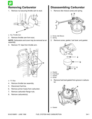
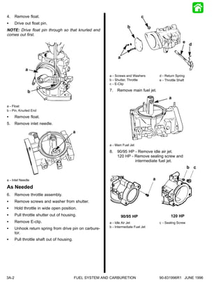
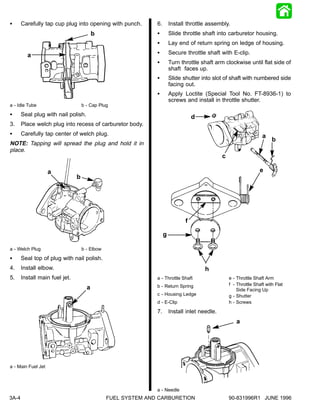
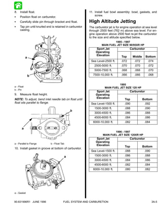
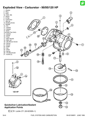
FUEL SYSTEM &
CARBURETION


                                                      3
                                                      A


 CARBURETOR


90-831996R1 JUNE 1996   FUEL SYSTEM AND CARBURETION   3A-–1
Table Of Contents
                                                                    Page
Removing Carburetor . . . . . . . . . . . . . . . . . . . . .       3A-1
Disassembling Carburetor . . . . . . . . . . . . . . . . .          3A-1
Assembling Carburetor . . . . . . . . . . . . . . . . . . .         3A-3
High Altitude Jetting . . . . . . . . . . . . . . . . . . . . . .   3A-5
Exploded View -
   Carburetor - 90/95/120 HP . . . . . . . . . . . . .              3A-6


3A-0                                                 FUEL SYSTEM AND CARBURETION   90-831996R1 JUNE 1996
Removing Carburetor                                  Disassembling Carburetor
1.   Remove nut securing throttle cam to stud.       1.       Remove idle mixture screw and spring.
                                                                                     a b


                a
a - Nut, Throttle Cam
                                                     a - Screw, Idle Mixture
2.   Remove throttle cam form stud.                  b - Spring

NOTE: Carburetors and cover may be removed as an     2.       Remove screw, gasket, fuel bowl, and gasket.
assembly.
3.   Remove “E” clips from throttle arm.


                                                                                             a


                                                 a                                               b

                                                                                             c
                                                                                         d
                                                     a   -   Gasket
                                                     b   -   Fuel Bowl
                                                     c   -   Gasket
                                                     d   -   Screw

a - “E” Clips                                        3.       Remove fuel bowl gasket from groove in carbure-
                                                              tor.
4.   Remove throttle bar assembly.
5.   Disconnect fuel line.                                                                   a
6.   Remove primer hoses from carburetor.
7.   Remove carburetor flange nuts.
8.   Remove carburetor(s).


                                                     a - Gasket


90-831996R1 JUNE 1996                 FUEL SYSTEM AND CARBURETION                                       3A-1
4.     Remove float.                                                              c
S      Drive out float pin.
                                                                        b
NOTE: Drive float pin through so that knurled end
comes out first.
                                                                                                            e
                                                                                                                 d

                                                                 a

             a
                                                            a - Screws and Washers          d - Return Spring
                                                            b - Shutter, Throttle           e - Throttle Shaft
                                                            c - E-Clip

              b                                             7.   Remove main fuel jet.
                                                                                                  a
a - Float
b - Pin, Knurled End
S      Remove float.
5.     Remove inlet needle.

                                             a

                                                            a - Main Fuel Jet

                                                            8.   90/95 HP - Remove idle air jet.
                                                                 120 HP - Remove sealing screw and
                                                                          intermediate fuel jet.
                                                                                                                 b c

a - Inlet Needle                                                                        a
As Needed
6.     Remove throttle assembly.
S      Remove screws and washer from shutter.
S      Hold throttle in wide open position.
S      Pull throttle shutter out of housing.                         90/95 HP                       120 HP
S      Remove E-clip.                                       a - Idle Air Jet                c - Sealing Screw
                                                            b - Intermediate Fuel Jet
S      Unhook return spring from drive pin on carbure-
       tor.
S      Pull throttle shaft out of housing.


3A-2                                         FUEL SYSTEM AND CARBURETION                    90-831996R1 JUNE 1996
9.   Remove elbow.                                         NOTE: In some cases, the position of the idle tube
                                                           may make it necessary to remove the tube prior to re-
                             a
                                                           moving the nozzle.


                                                           13. Inspect the following:
                                                                     Inspect:                     Look For:
                                                           Idle mixture screw           Rings or grooves on point
                                                           Inlet needle                 Rings or grooves on point
                                                           Idle spring                  Compressed spring
                                                           Primer connectors            Clogging
                                                           Body                         Pitting
a - Elbow
                                                           Jets                         Clogging
10. Remove welch plug.
S    Drill hole through welch plug.
IMPORTANT: Do not drill into carburetor body.
S    Insert a small screwdriver in hole and pry plug out
     of housing.


                                                           14. Clean entire carburetor with solvent.
11. Remove idle tube.                                      IMPORTANT: Do not allow non-metal parts to
                                                           come in contact with solvent.
S    Place punch on bottom end of idle tube.
IMPORTANT: Note the depth of the idle tube prior                                     WARNING
to removal. It must be installed to this position.
                                                           Follow solvent manufacturer’s directions for use.
S    Carefully tap on punch until cup plug and idle
     tube come free of body channel.                       Assembling Carburetor
12. Unscrew main nozzle and remove it from body            1.   Thread main nozzle into body channel.
    channel.
                                                           IMPORTANT: Idle tube must contact nozzle in
                                                           front or carburetor will run lean.
                  a                                        NOTE: Be sure nozzle is threaded in completely. Do
                                                           not over tighten nozzle.
                                                           2.   Install idle tube.
                                                           S    Slide idle tube (flanged end up) into body chan-
                                                                nel.
                                                           IMPORTANT: Idle tube must contact nozzle in
                                                           front or engine will run lean.

a - Main Nozzle


90-831996R1 JUNE 1996                   FUEL SYSTEM AND CARBURETION                                           3A-3
S      Carefully tap cup plug into opening with punch.         6.       Install throttle assembly.
                                          b                    S        Slide throttle shaft into carburetor housing.
                                                               S        Lay end of return spring on ledge of housing.

         a                                                     S        Secure throttle shaft with E-clip.
                                                               S        Turn throttle shaft arm clockwise until flat side of
                                                                        shaft faces up.
                                                               S        Slide shutter into slot of shaft with numbered side
                                                                        facing out.
                                                               S        Apply Loctite (Special Tool No. FT-8936-1) to
                                                                        screws and install in throttle shutter.
a - Idle Tube                       b - Cap Plug

S      Seal plug with nail polish.                                                 d
3.     Place welch plug into recess of carburetor body.
S      Carefully tap center of welch plug.                                                                           a
                                                                                                                          b
NOTE: Tapping will spread the plug and hold it in
place.
                                                                                                c

                    a                                                                                               e
                                b


                                                                               f

                                                                    g

a - Welch Plug                      b - Elbow

S      Seal top of plug with nail polish.
4.     Install elbow.                                                                  h
5.     Install main fuel jet.                                  a - Throttle Shaft                   e - Throttle Shaft Arm
                                                               b - Return Spring                    f - Throttle Shaft with Flat
                                      a                                                                 Side Facing Up
                                                               c - Housing Ledge                    g - Shutter
                                                               d - E-Clip                           h - Screws

                                                               7.       Install inlet needle.
                                                                                                       a


a - Main Fuel Jet


                                                               a - Needle
3A-4                                            FUEL SYSTEM AND CARBURETION                         90-831996R1 JUNE 1996
8.   Install float.                                        11. Install fuel bowl assembly: bowl, gaskets, and
                                                               screw.
S    Position float on carburetor.
S    Carefully slide pin through bracket and float.        High Altitude Jetting
S    Tap pin until knurled end is retained in carburetor   The carburetor jet is for engine operation at sea level
     casting.                                              through 2500 feet (762 m) above sea level. For en-
                                                           gine operation above 2500 feet re-jet the carburetor
                                                           to the size and altitude specified below.
                                                                              1995 - 1997
                                                                     MAIN FUEL JET SIZE 90/95XR HP
                                                                Sport Jet                   Carburetor
                                                                Operating
                                                                O    ti
                                                                Elevation            Top      Middle     Bottom
            a
                                                            Sea Level-2500 ft.       .072      .072       .074
                                                               2500-5000 ft.         .070      .070       .072
                                                               5000-7500 ft.         .068      .068       .070
                b                                             7500-10,000 ft.        .066      .066       .068


                                                                                 1995
a - Float                                                              MAIN FUEL JET SIZE 120 HP
b - Pin
                                                                Sport Jet                   Carburetor
9.   Measure float height.                                      Operating
                                                                O    ti
NOTE: To adjust, bend inlet needle tab on float until           Elevation               Top            Bottom
float sits parallel to flange.                              Sea Level-1500 ft.         .090             .092
                                                               1500-3000 ft.           .088             .090
                                              b
                                                               3000-4500 ft.           .086             .088
                                                               4500-6000 ft.           .084             .086
                                                              6000-10,000 ft.          .082             .084

       a
                                                                              1996 - 1997
                                                                      MAIN FUEL JET SIZE 120XR HP
                                                                Sport Jet                   Carburetor
                                                                Operating
                                                                O    ti
a - Parallel to Flange        b - Float Tab
                                                                Elevation               Top            Bottom
10. Install gasket in groove at bottom of carburetor.
                                                            Sea Level-1500 ft.         .088             .090
                                          a                    1500-3000 ft.           .086             .088
                                                               3000-4500 ft.           .084             .086
                                                               4500-6000 ft.           .082             .084
                                                              6000-10,000 ft.          .080             .082


a - Gasket


90-831996R1 JUNE 1996                     FUEL SYSTEM AND CARBURETION                                          3A-5
Exploded View - Carburetor - 90/95/120 HP
 1 - Gasket
 2 - Plug
 3 - Plug                                                                                     4
 3a -Tube, Idle
 4 - Elbow                                                                   3
 5 - E-Clip                                             1
 6 - Carburetor
 7 - Idle Jet
 7a -Sealing Screw                                                       2
 8 - Needle
 10 - Pin                                                                                         5
 11 - Gasket
 12 - Gasket
 13 - Bowl
 13a Bowl (Top Carb)                         27
 14 - Gasket
                                                                                          6
 15 - Screw
 16 - Float                           B            26
 17 - Main Nozzle                                       25
 18 - Main Jet
 19 - Idle Mixture Screw
 20 - Spring
 21 - Screw                           23      24                                                            7
 22 - Roller
 23 - Nut                       22
 24 - Shaft                21
 25 - Spring
 26 - Throttle Shutter
 27 - Screw (2)                                    20                                 8
                                                             18
                                                                    17

                       3                           19


                      3a
                                                             16
                                                                                                       10

                           7
                                 7a

                                                                                                  11


                                                                                 12

                                                              13a
                120 HP
                                                                                              13


                                                                                 14
  Quicksilver Lubrication/Sealant
  Application Points                                                             15

            B       Loctite 271 (92-823089--1)

3A-6                                      FUEL SYSTEM AND CARBURETION             90-831996R1 JUNE 1996

3a carburetor

  • 1.
    FUEL SYSTEM & CARBURETION 3 A CARBURETOR 90-831996R1 JUNE 1996 FUEL SYSTEM AND CARBURETION 3A-–1
  • 2.
    Table Of Contents Page Removing Carburetor . . . . . . . . . . . . . . . . . . . . . 3A-1 Disassembling Carburetor . . . . . . . . . . . . . . . . . 3A-1 Assembling Carburetor . . . . . . . . . . . . . . . . . . . 3A-3 High Altitude Jetting . . . . . . . . . . . . . . . . . . . . . . 3A-5 Exploded View - Carburetor - 90/95/120 HP . . . . . . . . . . . . . 3A-6 3A-0 FUEL SYSTEM AND CARBURETION 90-831996R1 JUNE 1996
  • 3.
    Removing Carburetor Disassembling Carburetor 1. Remove nut securing throttle cam to stud. 1. Remove idle mixture screw and spring. a b a a - Nut, Throttle Cam a - Screw, Idle Mixture 2. Remove throttle cam form stud. b - Spring NOTE: Carburetors and cover may be removed as an 2. Remove screw, gasket, fuel bowl, and gasket. assembly. 3. Remove “E” clips from throttle arm. a a b c d a - Gasket b - Fuel Bowl c - Gasket d - Screw a - “E” Clips 3. Remove fuel bowl gasket from groove in carbure- tor. 4. Remove throttle bar assembly. 5. Disconnect fuel line. a 6. Remove primer hoses from carburetor. 7. Remove carburetor flange nuts. 8. Remove carburetor(s). a - Gasket 90-831996R1 JUNE 1996 FUEL SYSTEM AND CARBURETION 3A-1
  • 4.
    4. Remove float. c S Drive out float pin. b NOTE: Drive float pin through so that knurled end comes out first. e d a a a - Screws and Washers d - Return Spring b - Shutter, Throttle e - Throttle Shaft c - E-Clip b 7. Remove main fuel jet. a a - Float b - Pin, Knurled End S Remove float. 5. Remove inlet needle. a a - Main Fuel Jet 8. 90/95 HP - Remove idle air jet. 120 HP - Remove sealing screw and intermediate fuel jet. b c a - Inlet Needle a As Needed 6. Remove throttle assembly. S Remove screws and washer from shutter. S Hold throttle in wide open position. S Pull throttle shutter out of housing. 90/95 HP 120 HP S Remove E-clip. a - Idle Air Jet c - Sealing Screw b - Intermediate Fuel Jet S Unhook return spring from drive pin on carbure- tor. S Pull throttle shaft out of housing. 3A-2 FUEL SYSTEM AND CARBURETION 90-831996R1 JUNE 1996
  • 5.
    9. Remove elbow. NOTE: In some cases, the position of the idle tube may make it necessary to remove the tube prior to re- a moving the nozzle. 13. Inspect the following: Inspect: Look For: Idle mixture screw Rings or grooves on point Inlet needle Rings or grooves on point Idle spring Compressed spring Primer connectors Clogging Body Pitting a - Elbow Jets Clogging 10. Remove welch plug. S Drill hole through welch plug. IMPORTANT: Do not drill into carburetor body. S Insert a small screwdriver in hole and pry plug out of housing. 14. Clean entire carburetor with solvent. 11. Remove idle tube. IMPORTANT: Do not allow non-metal parts to come in contact with solvent. S Place punch on bottom end of idle tube. IMPORTANT: Note the depth of the idle tube prior WARNING to removal. It must be installed to this position. Follow solvent manufacturer’s directions for use. S Carefully tap on punch until cup plug and idle tube come free of body channel. Assembling Carburetor 12. Unscrew main nozzle and remove it from body 1. Thread main nozzle into body channel. channel. IMPORTANT: Idle tube must contact nozzle in front or carburetor will run lean. a NOTE: Be sure nozzle is threaded in completely. Do not over tighten nozzle. 2. Install idle tube. S Slide idle tube (flanged end up) into body chan- nel. IMPORTANT: Idle tube must contact nozzle in front or engine will run lean. a - Main Nozzle 90-831996R1 JUNE 1996 FUEL SYSTEM AND CARBURETION 3A-3
  • 6.
    S Carefully tap cup plug into opening with punch. 6. Install throttle assembly. b S Slide throttle shaft into carburetor housing. S Lay end of return spring on ledge of housing. a S Secure throttle shaft with E-clip. S Turn throttle shaft arm clockwise until flat side of shaft faces up. S Slide shutter into slot of shaft with numbered side facing out. S Apply Loctite (Special Tool No. FT-8936-1) to screws and install in throttle shutter. a - Idle Tube b - Cap Plug S Seal plug with nail polish. d 3. Place welch plug into recess of carburetor body. S Carefully tap center of welch plug. a b NOTE: Tapping will spread the plug and hold it in place. c a e b f g a - Welch Plug b - Elbow S Seal top of plug with nail polish. 4. Install elbow. h 5. Install main fuel jet. a - Throttle Shaft e - Throttle Shaft Arm b - Return Spring f - Throttle Shaft with Flat a Side Facing Up c - Housing Ledge g - Shutter d - E-Clip h - Screws 7. Install inlet needle. a a - Main Fuel Jet a - Needle 3A-4 FUEL SYSTEM AND CARBURETION 90-831996R1 JUNE 1996
  • 7.
    8. Install float. 11. Install fuel bowl assembly: bowl, gaskets, and screw. S Position float on carburetor. S Carefully slide pin through bracket and float. High Altitude Jetting S Tap pin until knurled end is retained in carburetor The carburetor jet is for engine operation at sea level casting. through 2500 feet (762 m) above sea level. For en- gine operation above 2500 feet re-jet the carburetor to the size and altitude specified below. 1995 - 1997 MAIN FUEL JET SIZE 90/95XR HP Sport Jet Carburetor Operating O ti Elevation Top Middle Bottom a Sea Level-2500 ft. .072 .072 .074 2500-5000 ft. .070 .070 .072 5000-7500 ft. .068 .068 .070 b 7500-10,000 ft. .066 .066 .068 1995 a - Float MAIN FUEL JET SIZE 120 HP b - Pin Sport Jet Carburetor 9. Measure float height. Operating O ti NOTE: To adjust, bend inlet needle tab on float until Elevation Top Bottom float sits parallel to flange. Sea Level-1500 ft. .090 .092 1500-3000 ft. .088 .090 b 3000-4500 ft. .086 .088 4500-6000 ft. .084 .086 6000-10,000 ft. .082 .084 a 1996 - 1997 MAIN FUEL JET SIZE 120XR HP Sport Jet Carburetor Operating O ti a - Parallel to Flange b - Float Tab Elevation Top Bottom 10. Install gasket in groove at bottom of carburetor. Sea Level-1500 ft. .088 .090 a 1500-3000 ft. .086 .088 3000-4500 ft. .084 .086 4500-6000 ft. .082 .084 6000-10,000 ft. .080 .082 a - Gasket 90-831996R1 JUNE 1996 FUEL SYSTEM AND CARBURETION 3A-5
  • 8.
    Exploded View -Carburetor - 90/95/120 HP 1 - Gasket 2 - Plug 3 - Plug 4 3a -Tube, Idle 4 - Elbow 3 5 - E-Clip 1 6 - Carburetor 7 - Idle Jet 7a -Sealing Screw 2 8 - Needle 10 - Pin 5 11 - Gasket 12 - Gasket 13 - Bowl 13a Bowl (Top Carb) 27 14 - Gasket 6 15 - Screw 16 - Float B 26 17 - Main Nozzle 25 18 - Main Jet 19 - Idle Mixture Screw 20 - Spring 21 - Screw 23 24 7 22 - Roller 23 - Nut 22 24 - Shaft 21 25 - Spring 26 - Throttle Shutter 27 - Screw (2) 20 8 18 17 3 19 3a 16 10 7 7a 11 12 13a 120 HP 13 14 Quicksilver Lubrication/Sealant Application Points 15 B Loctite 271 (92-823089--1) 3A-6 FUEL SYSTEM AND CARBURETION 90-831996R1 JUNE 1996