Download to read offline


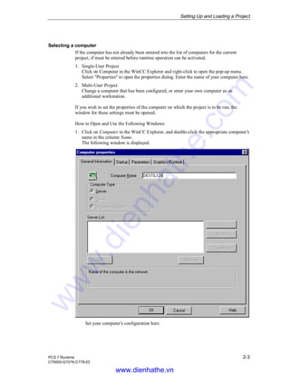
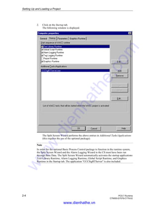


The chapter describes how to select, set up, and load a new WinCC project for runtime operation. This involves selecting the project, assigning a computer to run it, configuring screen settings using the Split Screen Wizard, and setting up the message system using the Alarm Logging Wizard. Loading the project activates it for monitoring and control on the runtime system.