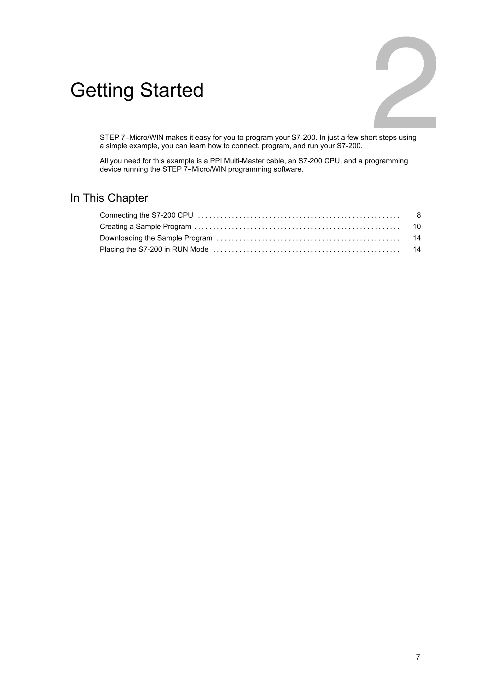
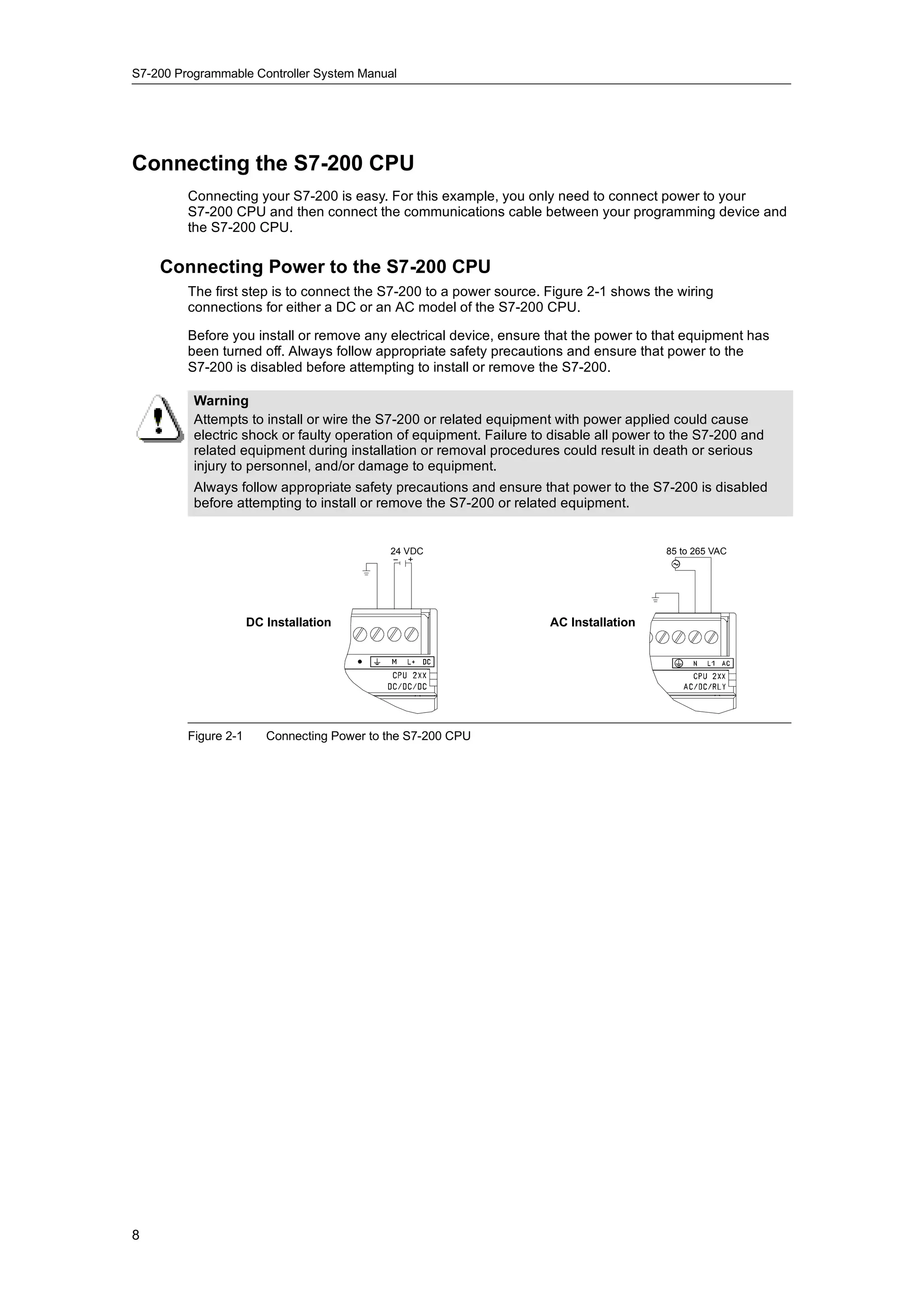
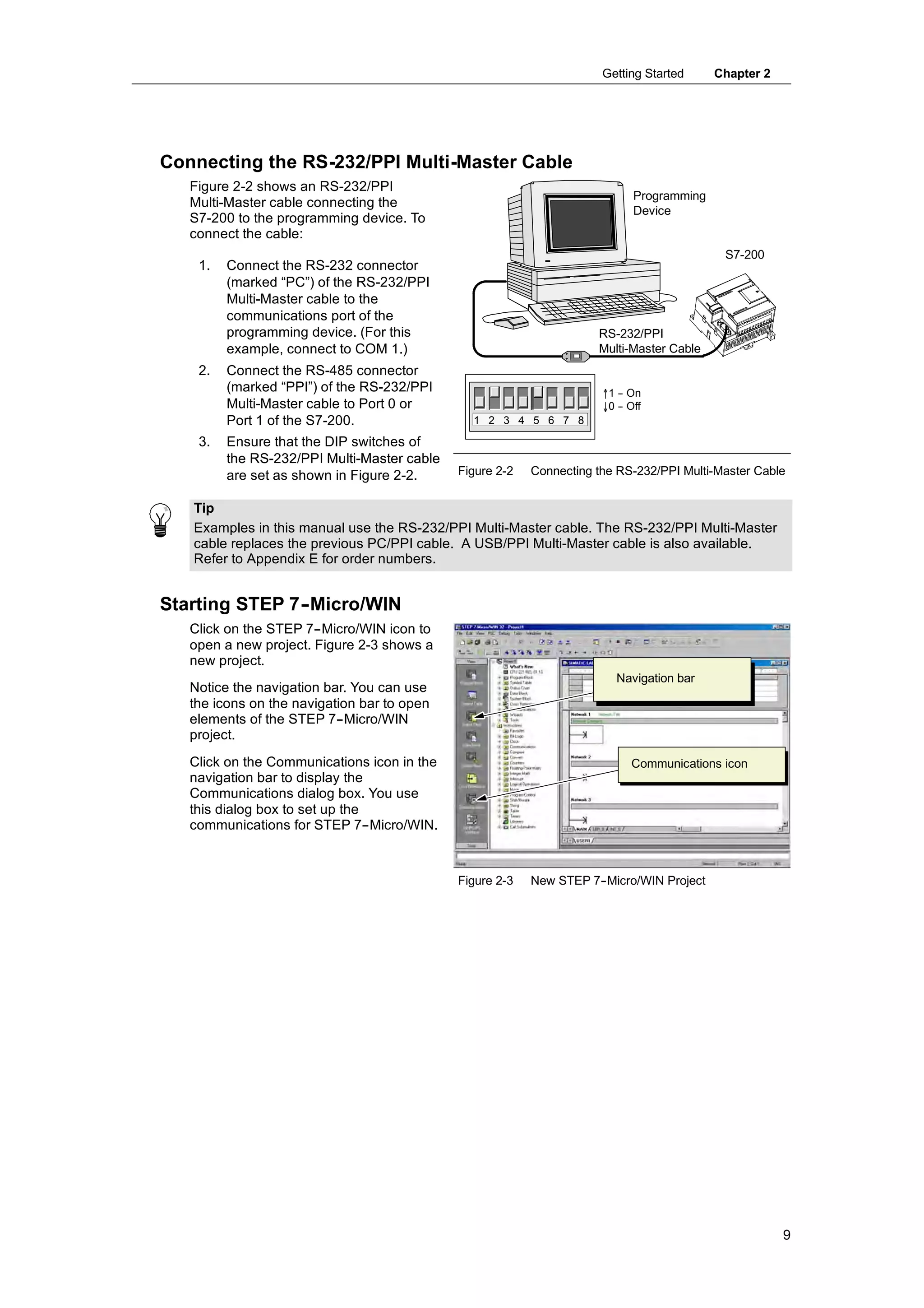
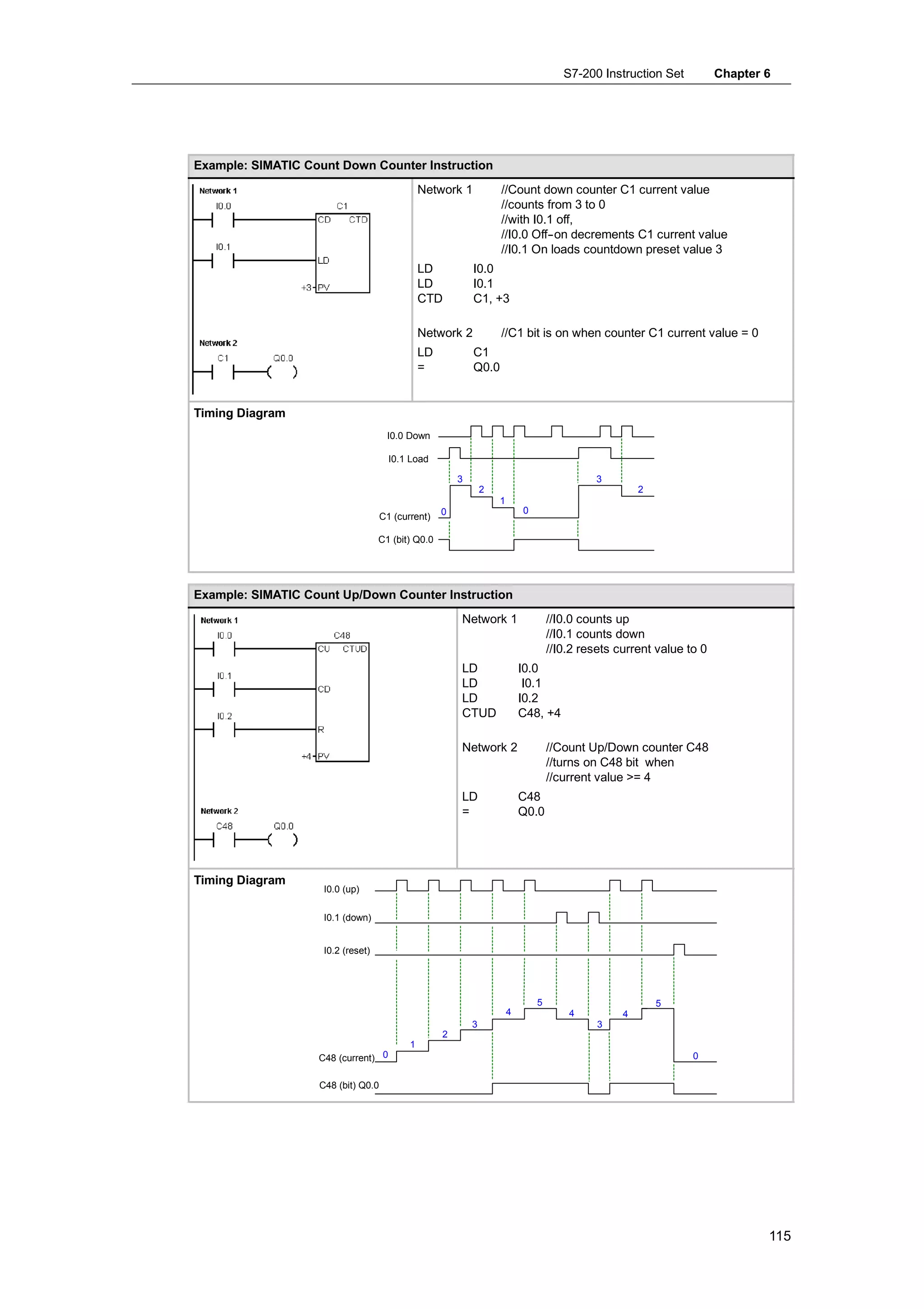
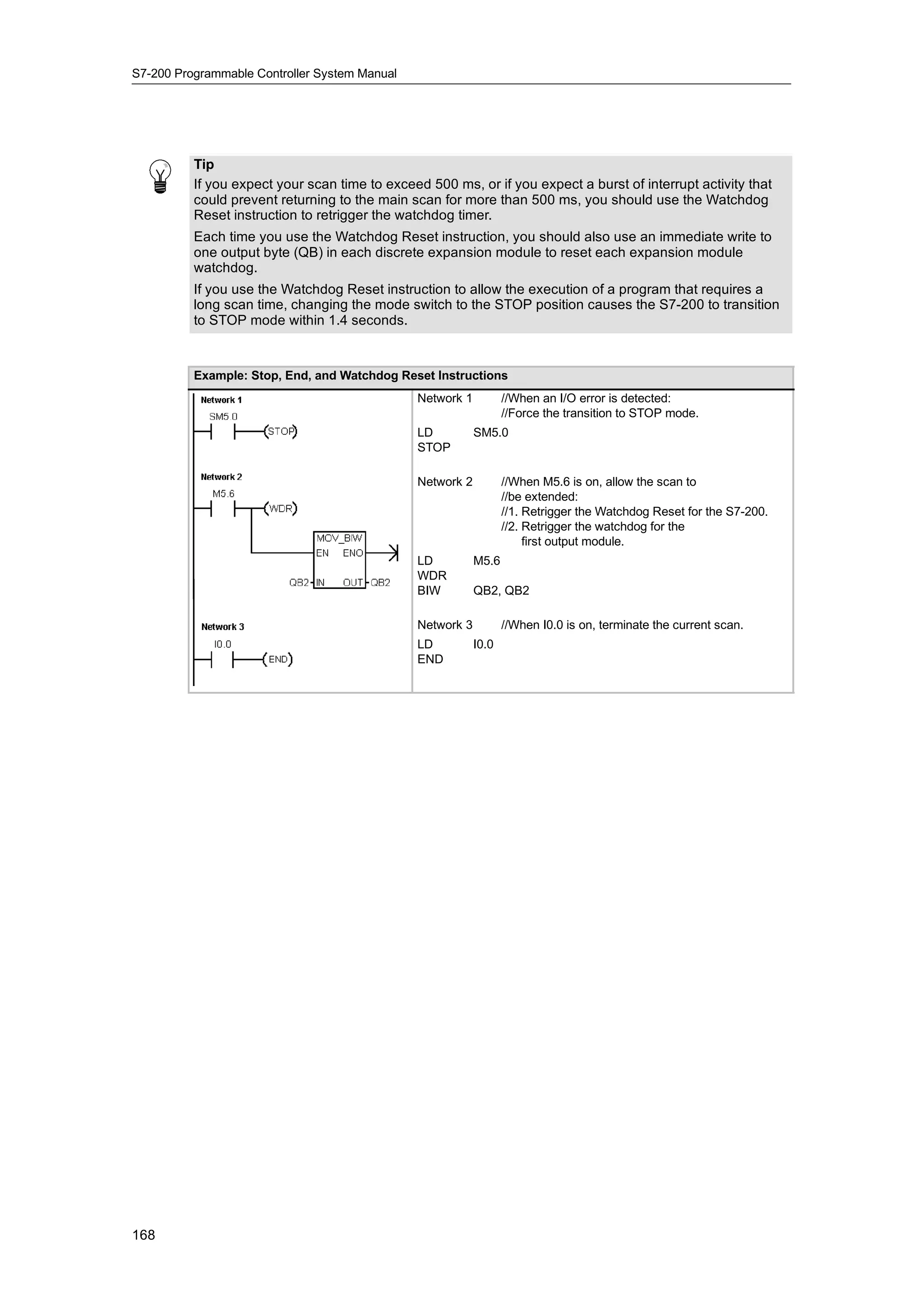
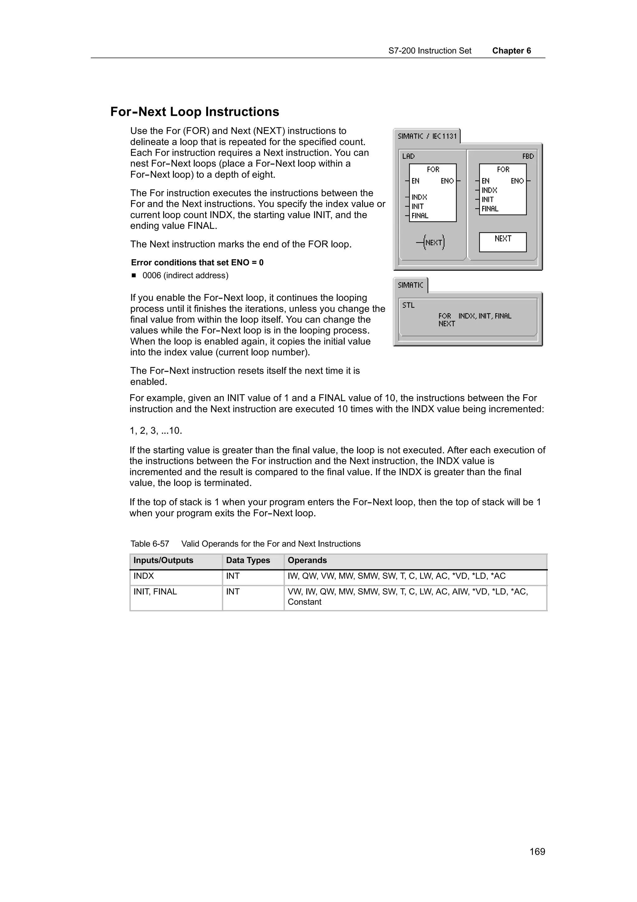
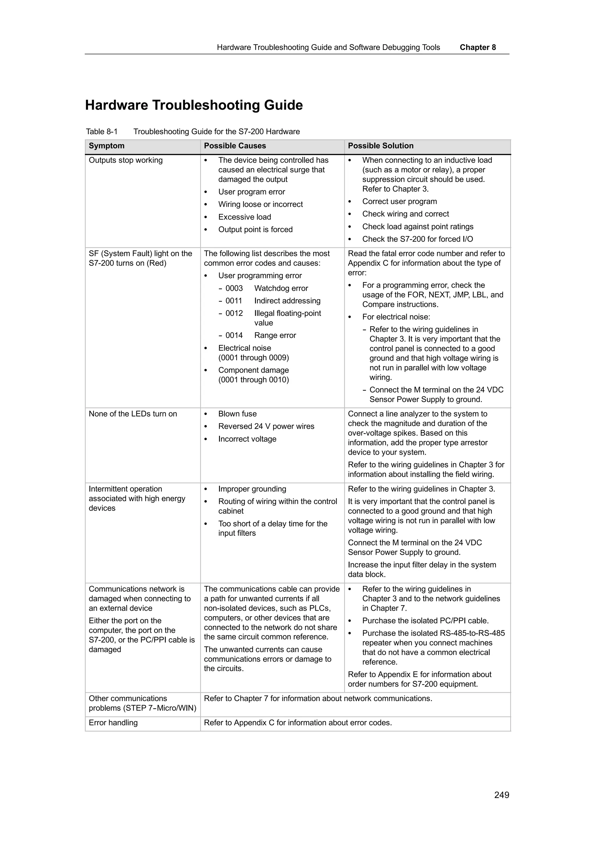
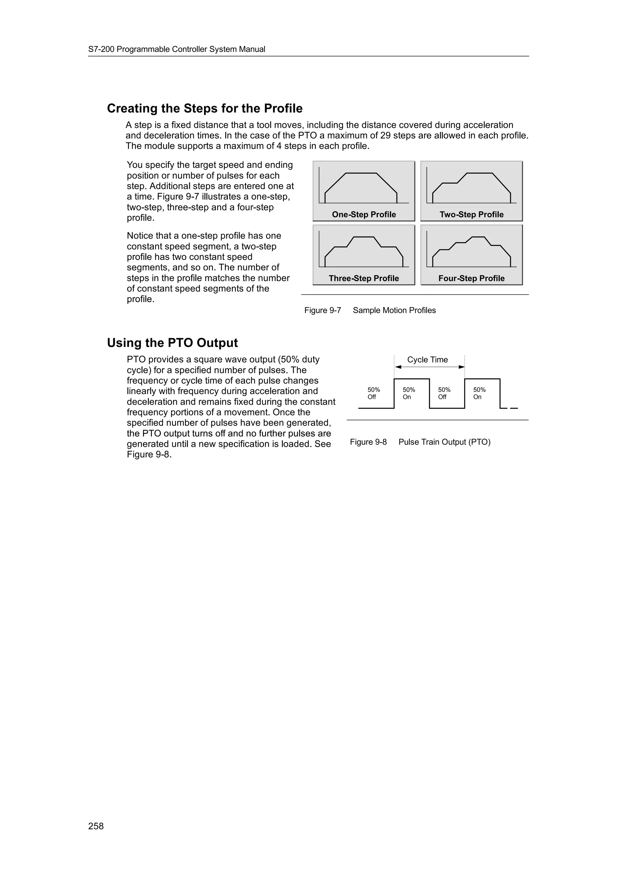
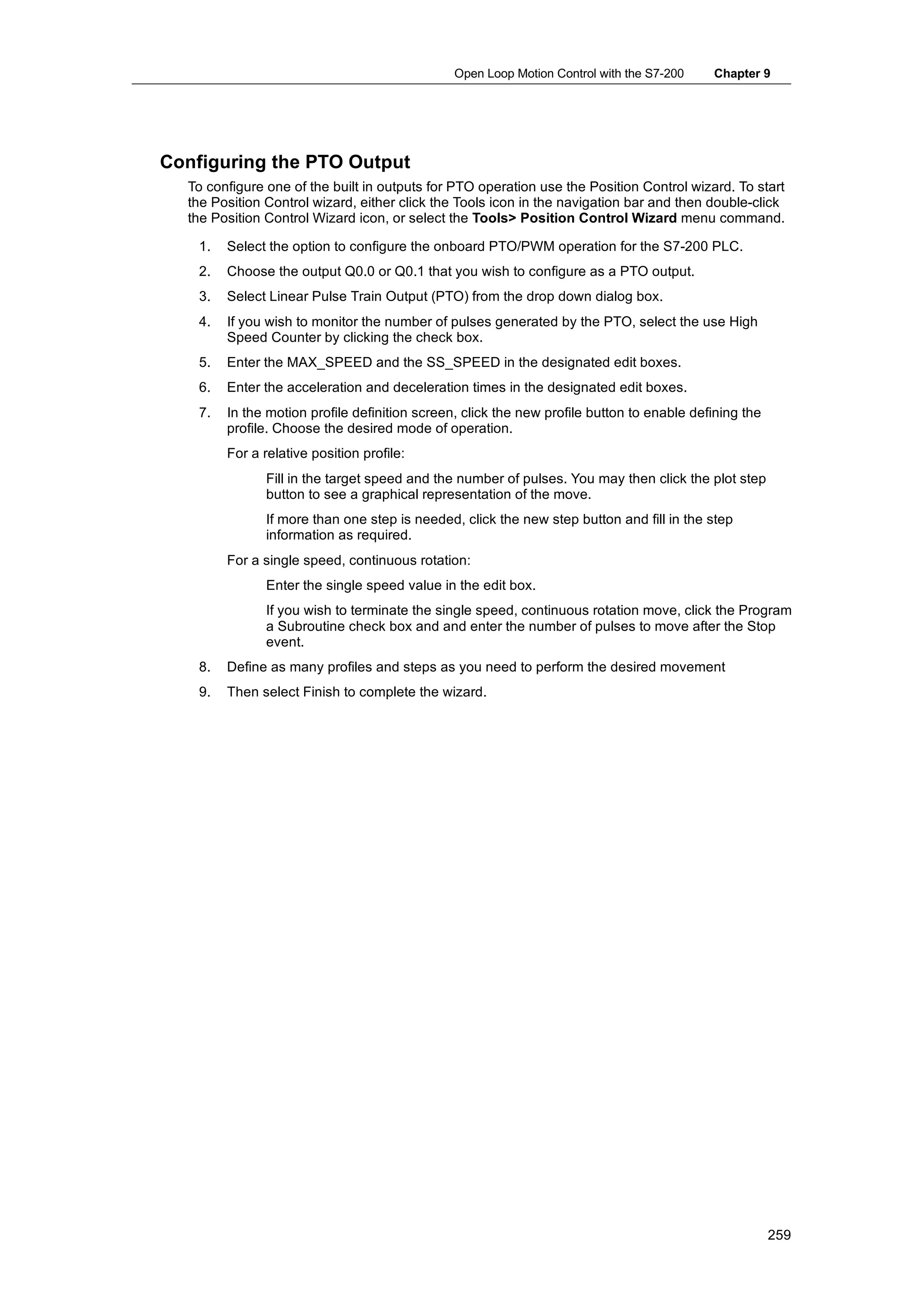
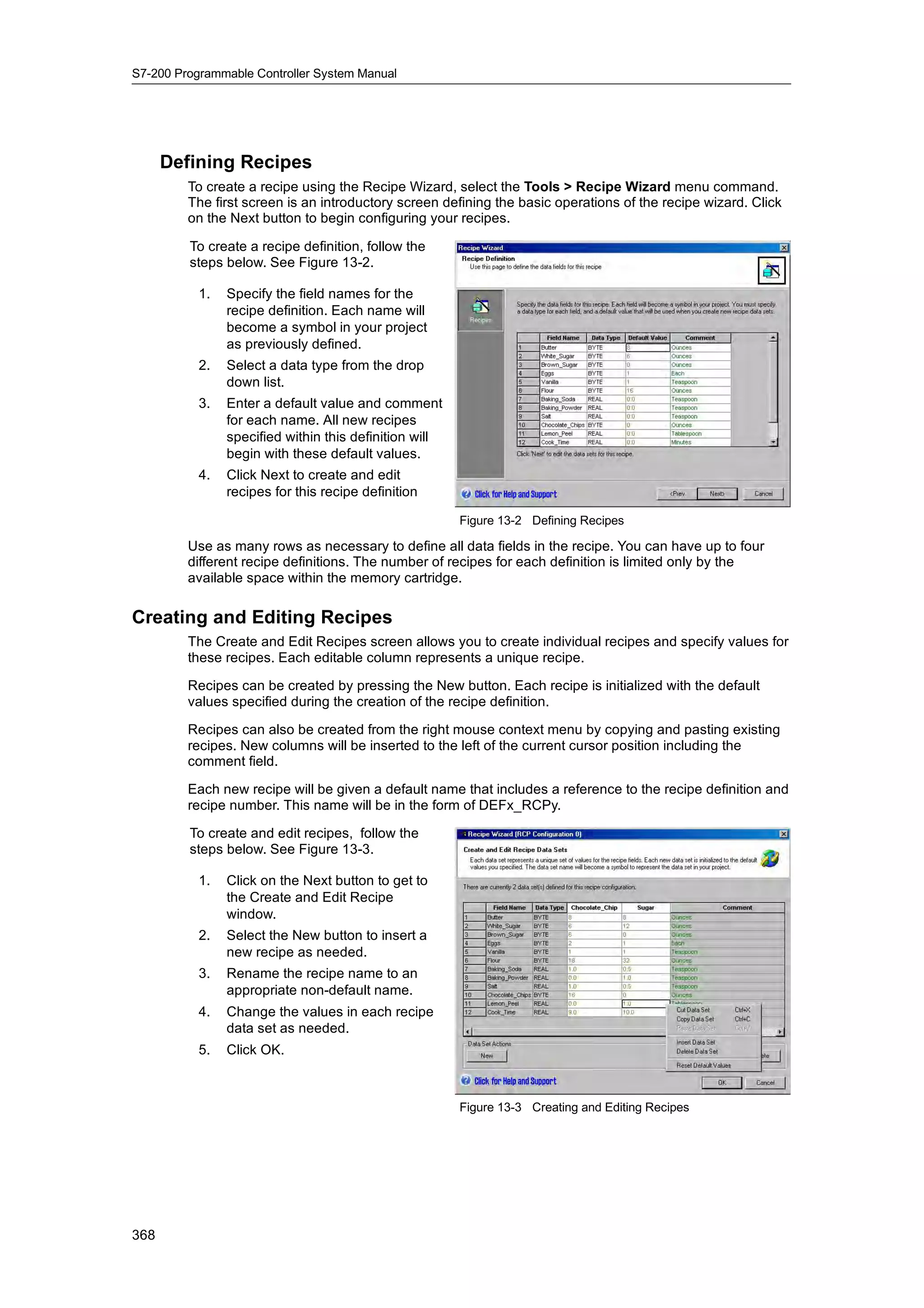
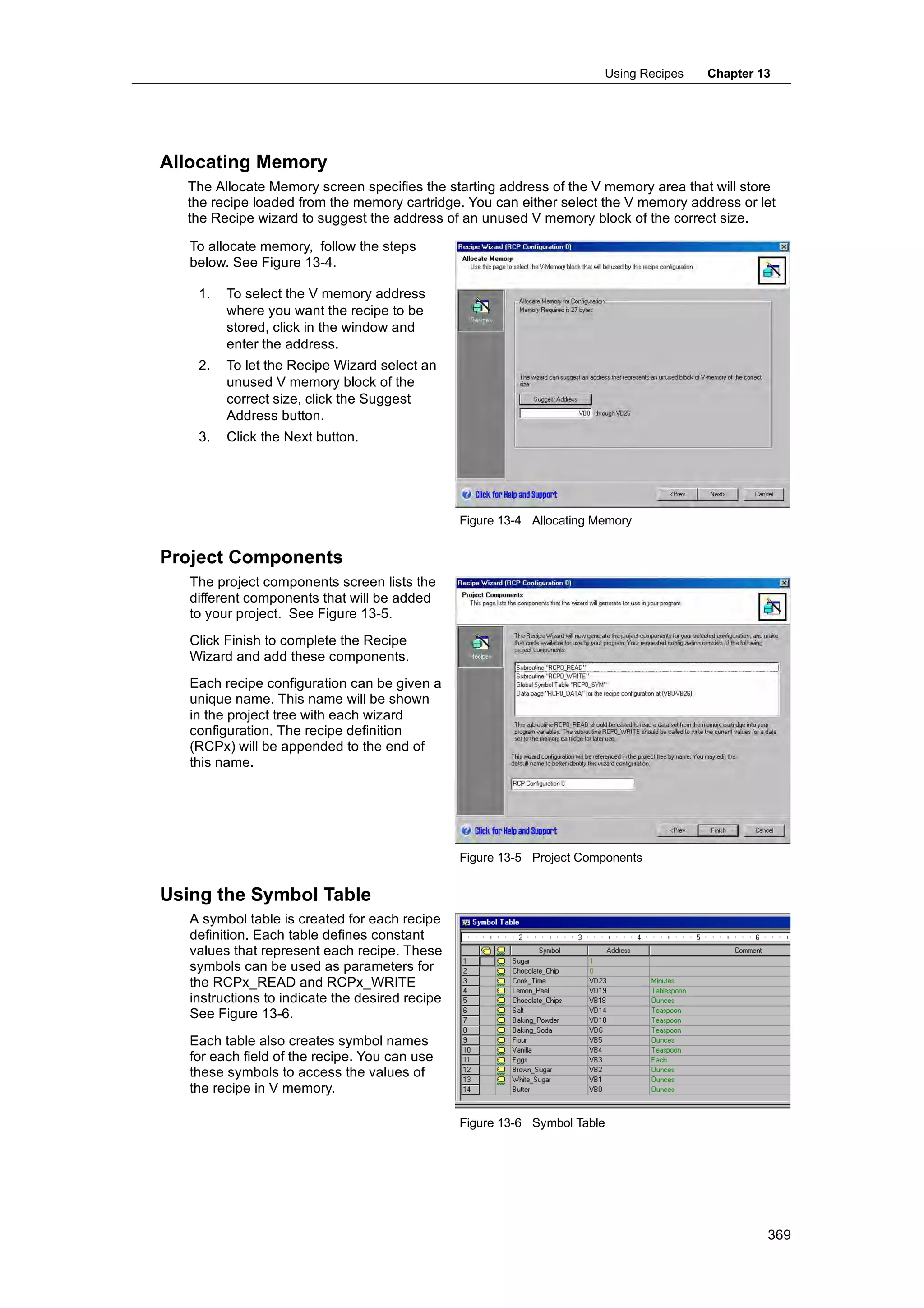
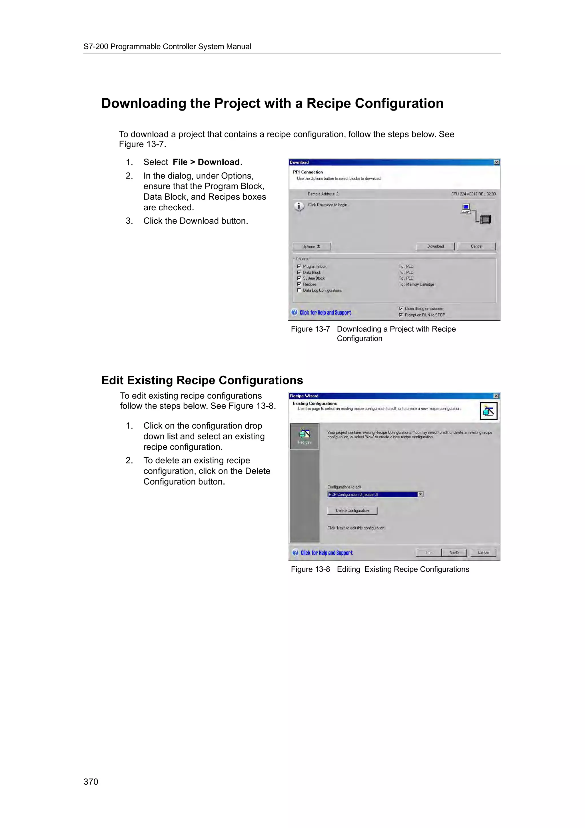
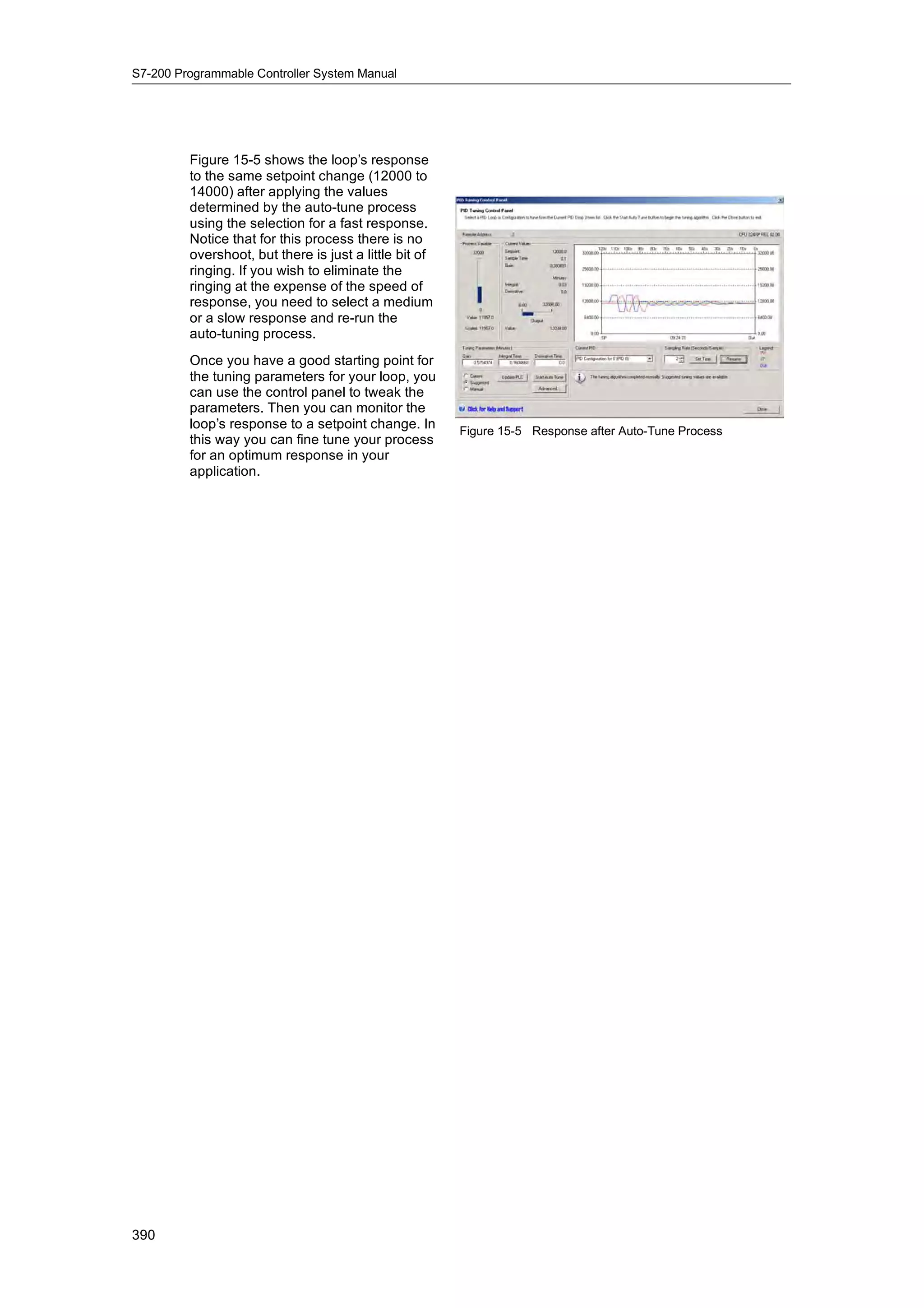
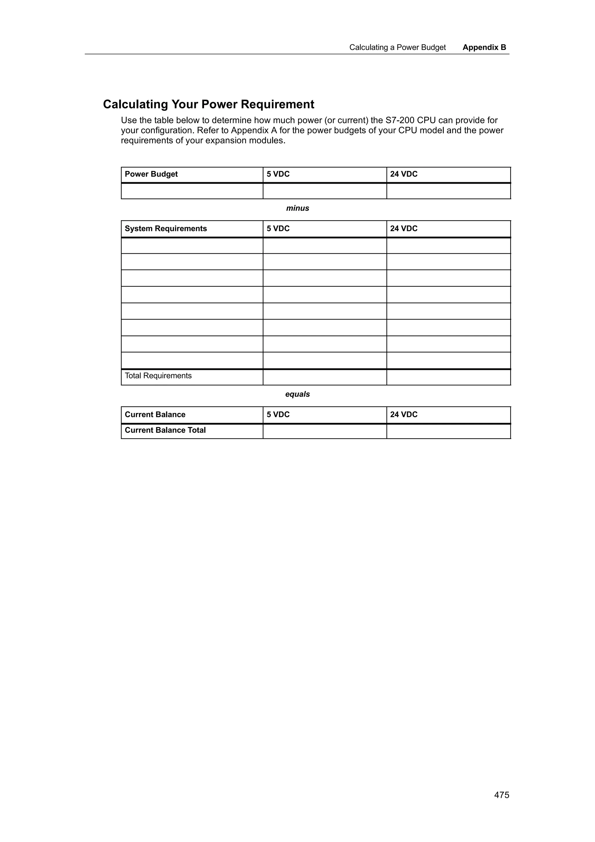
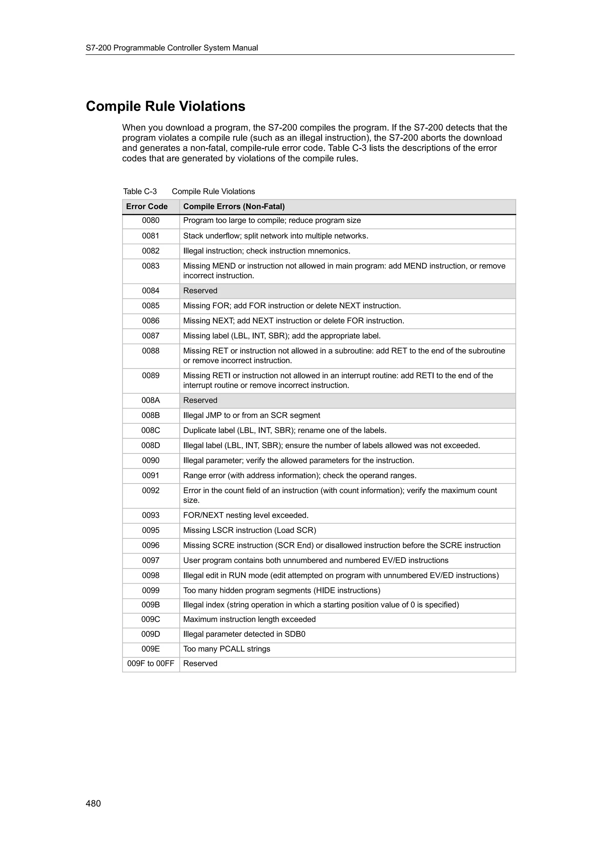
Downloaded 170 times

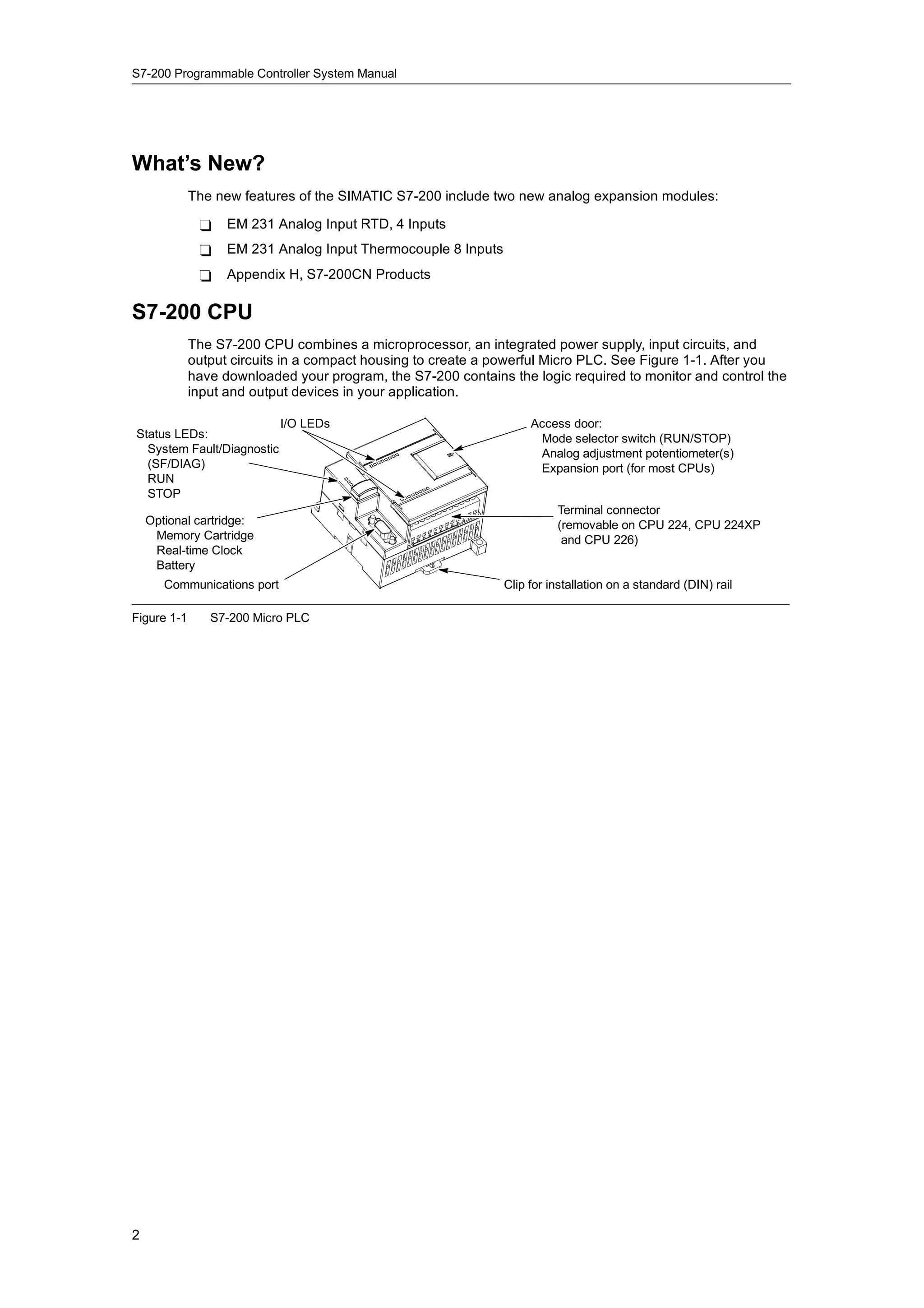
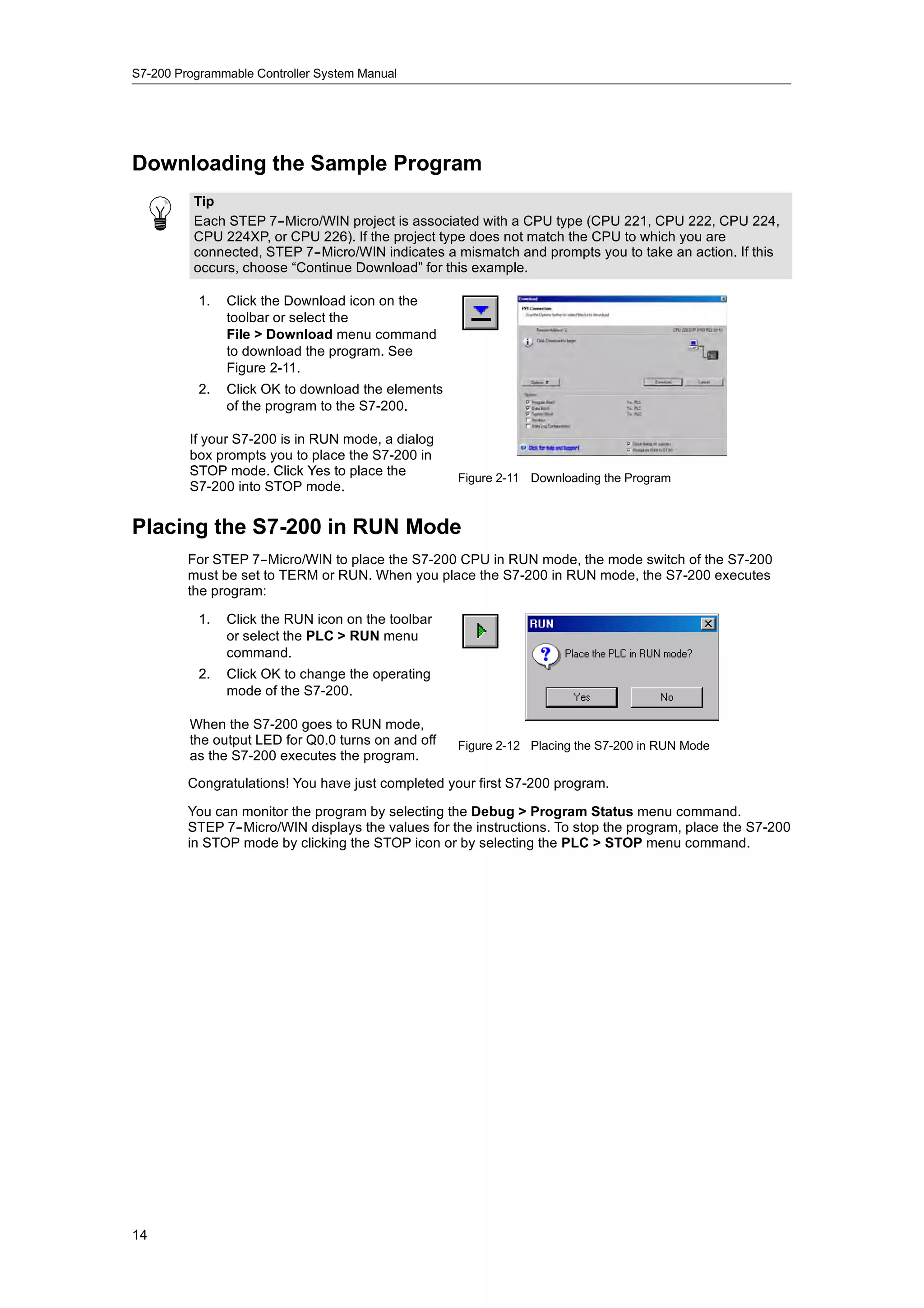

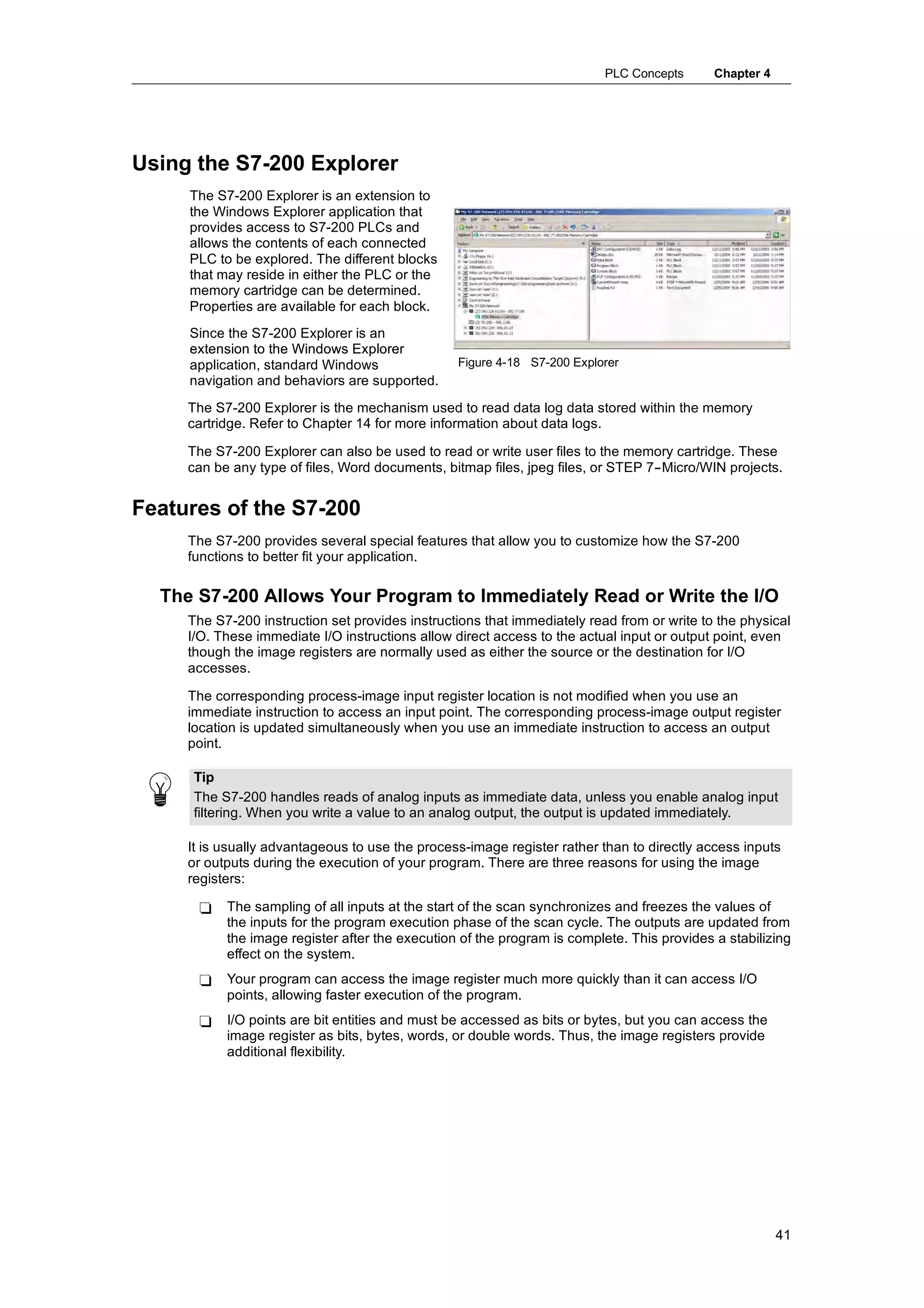
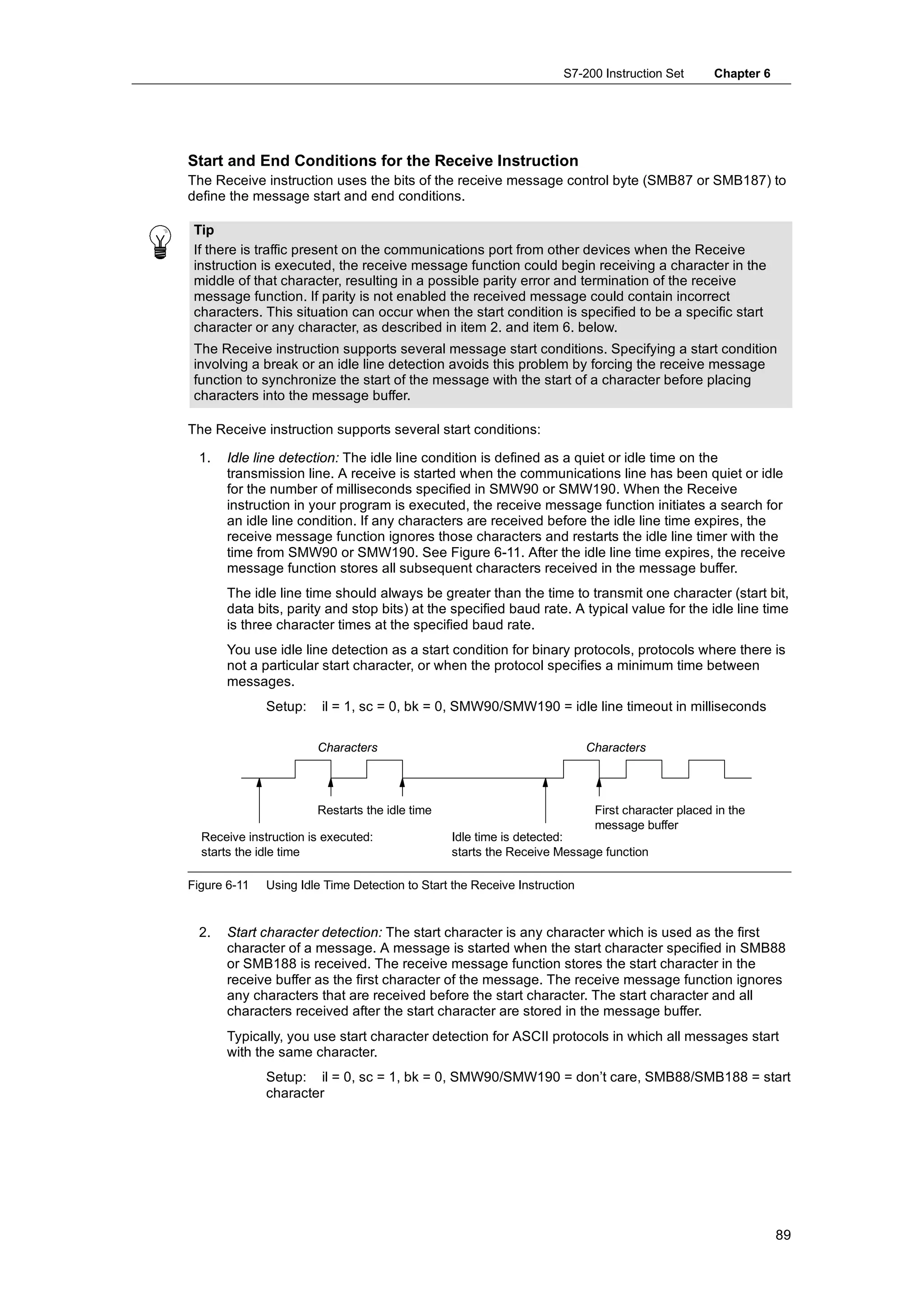
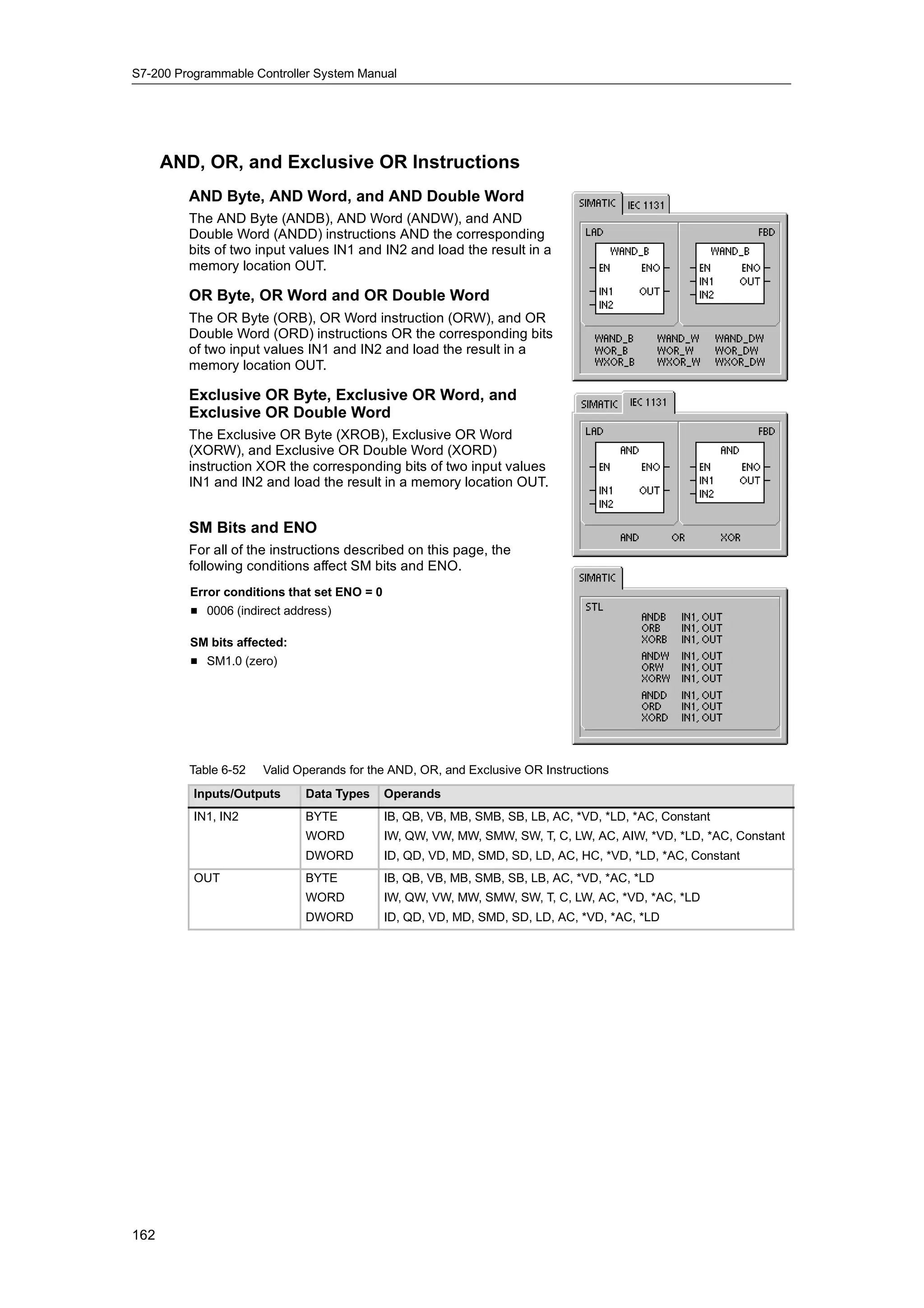
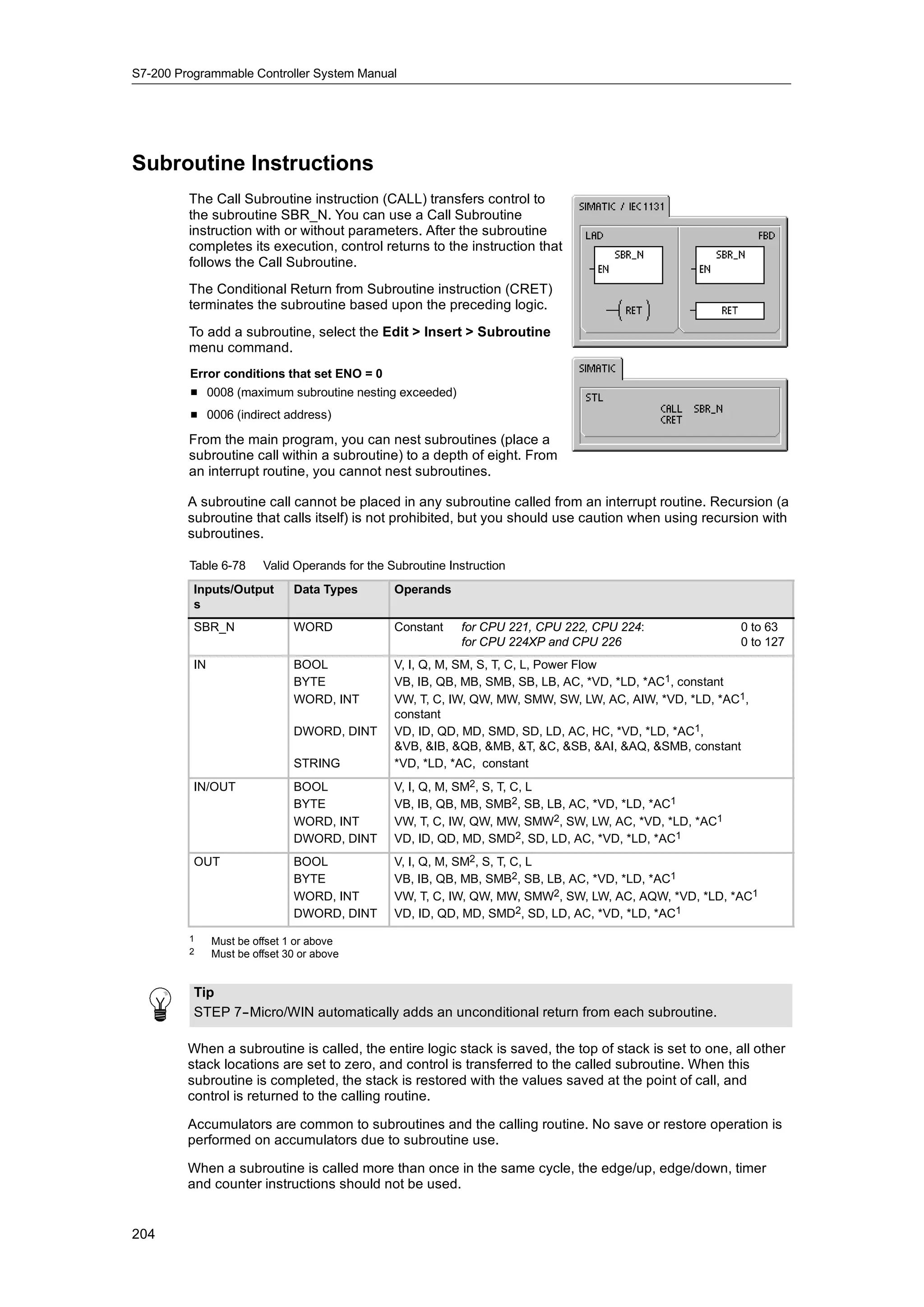
![S7-200 Programmable Controller System Manual
Data in other memory areas (such as T, C, HC, and the accumulators) are accessed by using an
address format that includes an area identifier and a device number.
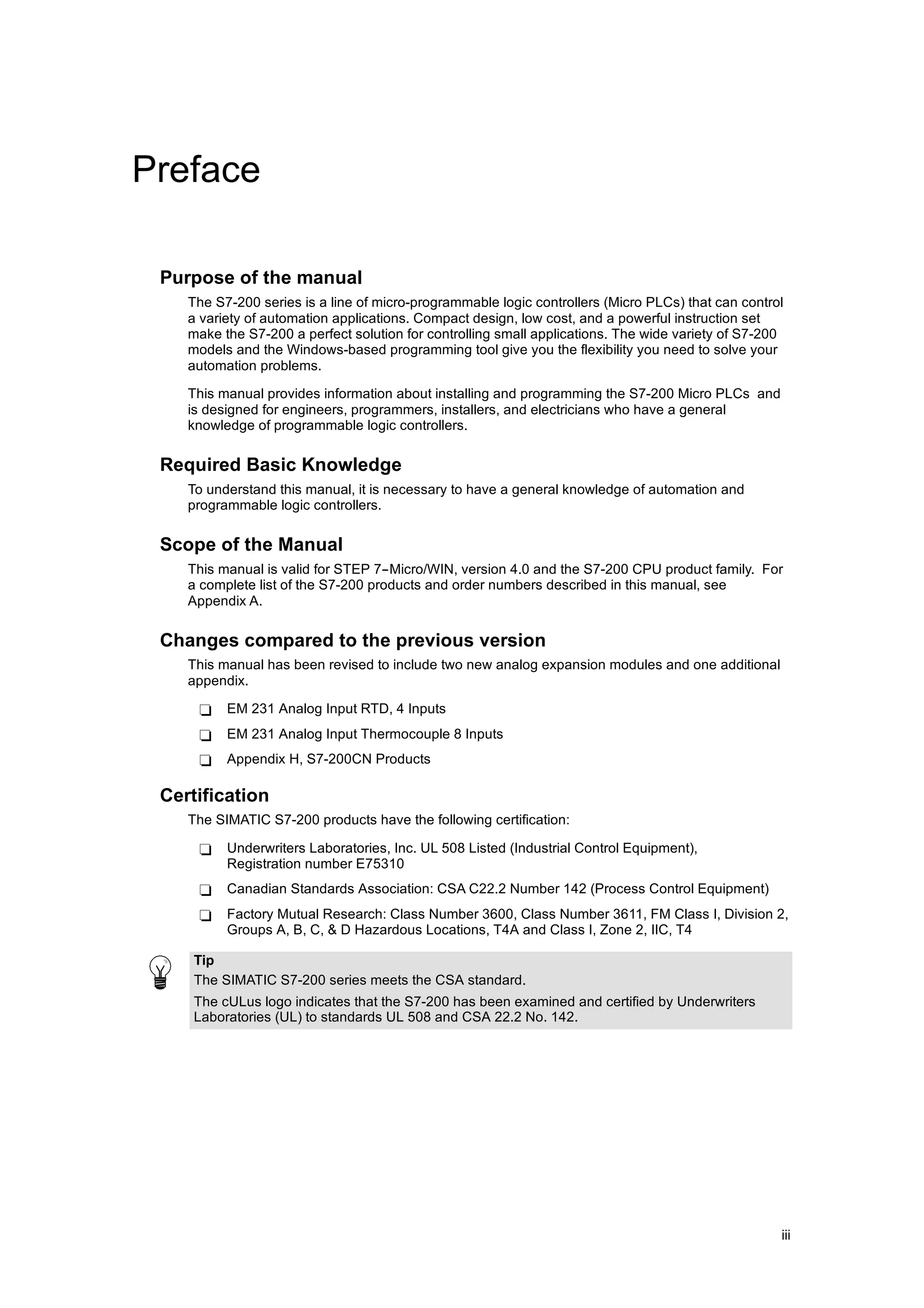
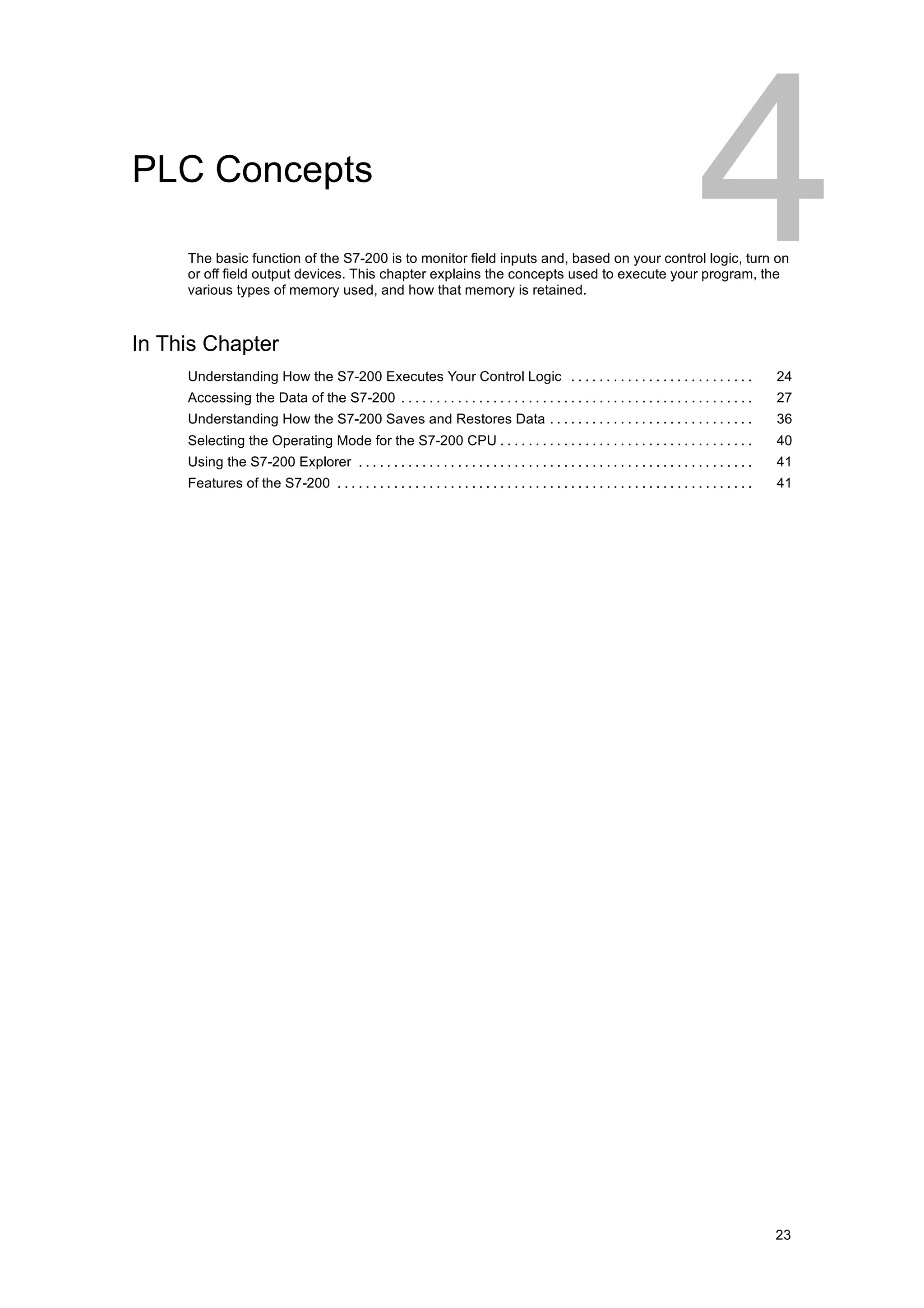
V B 100 V W 100 V D 100
Byte address Byte address Byte address
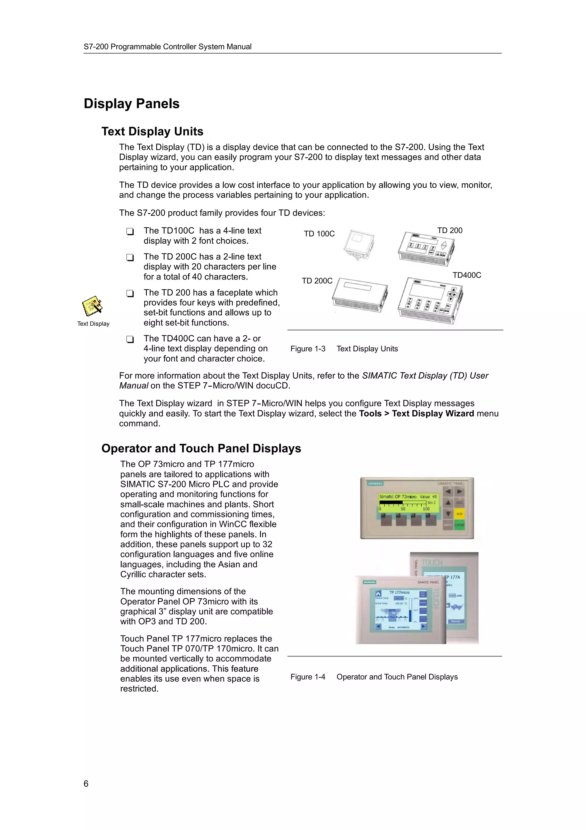
Access to a byte size Access to a word size Access to a double word size
Area identifier Area identifier Area identifier
MSB LSB
VB100 7 VB100 0
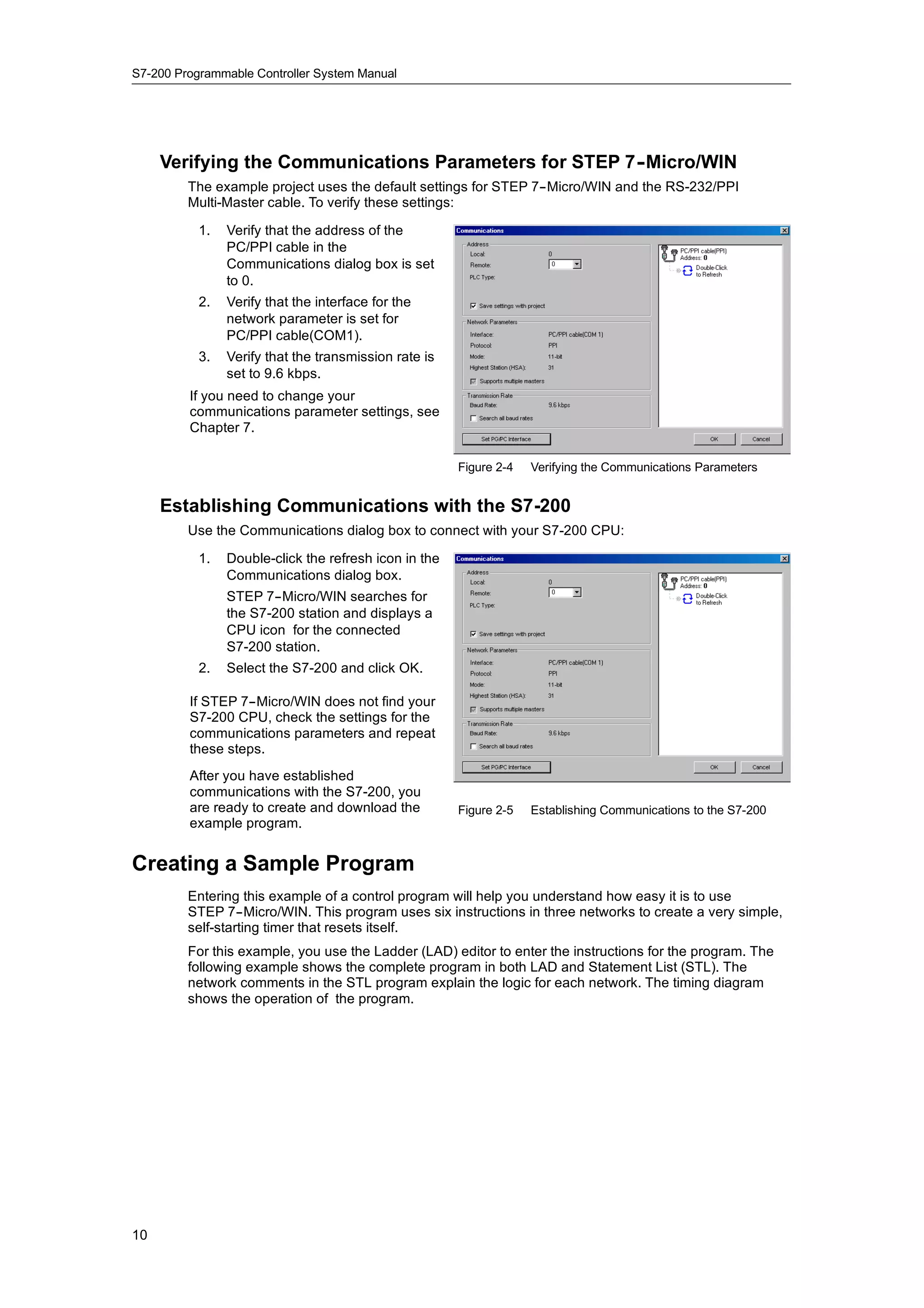
MSB = most significant bit
LSB = least significant bit
Most significant byte Least significant byte
MSB LSB
VW100 15 VB100 8 7 VB101 0
Most significant byte Least significant byte
MSB LSB
VD100 31 VB100 24 23 VB101 16 15 VB102 8 7 VB103 0
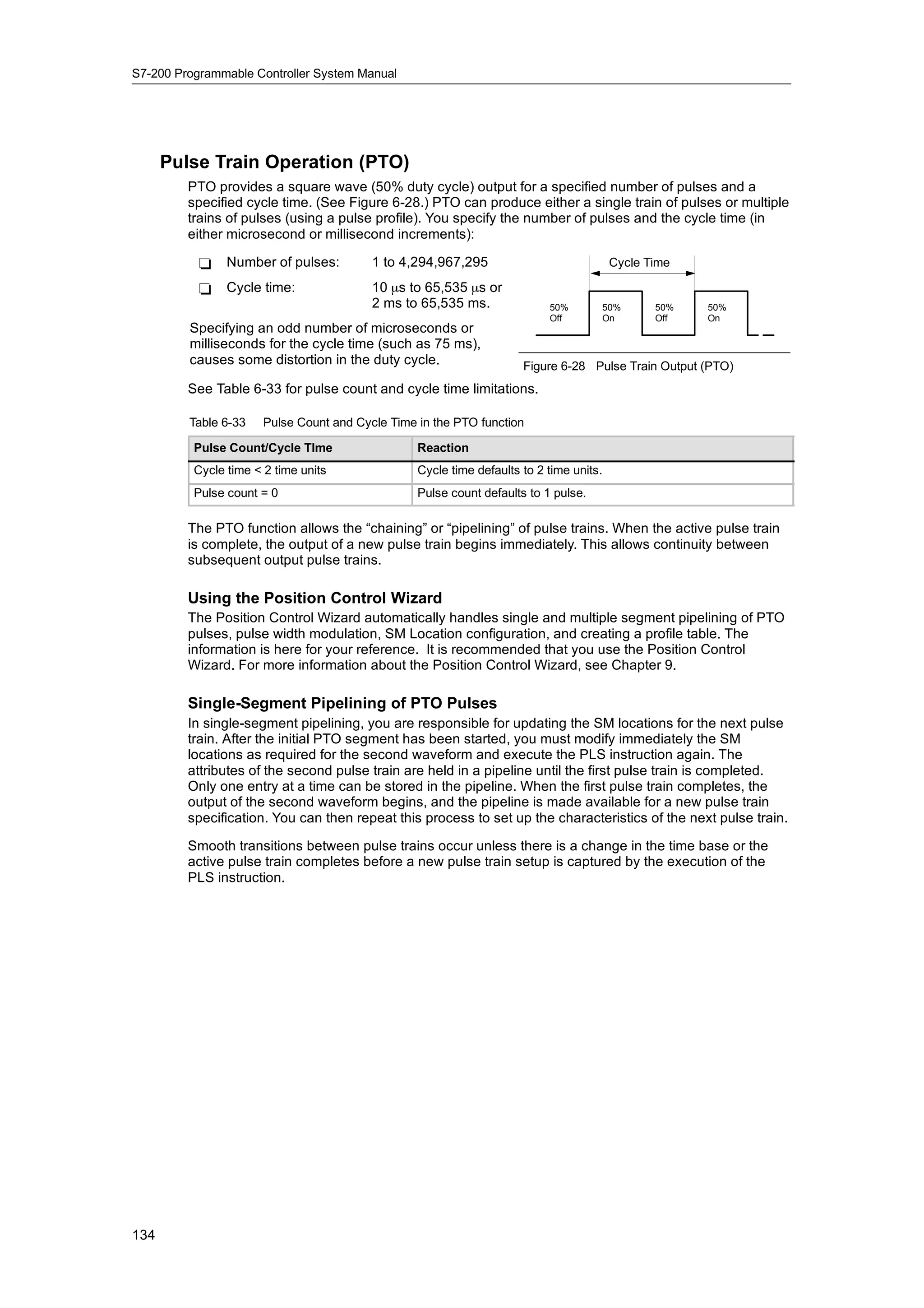
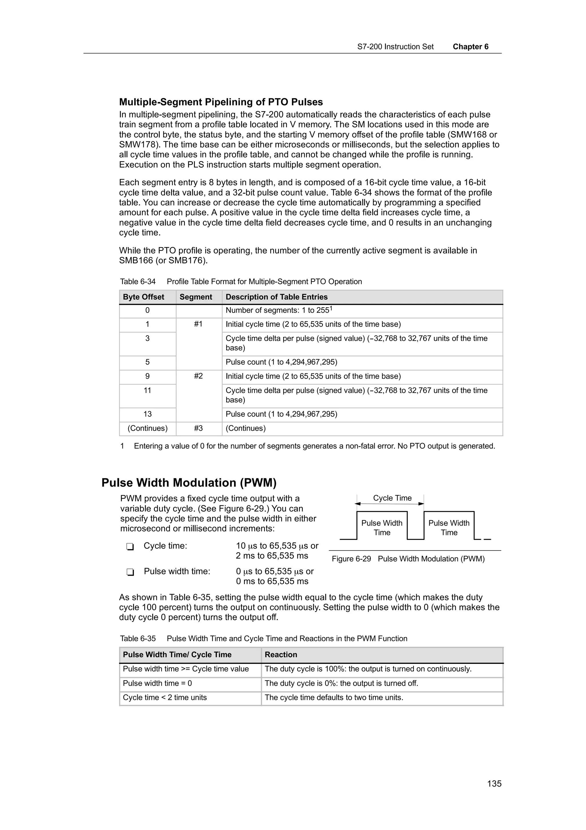
Figure 4-5 Comparing Byte, Word, and Double-Word Access to the Same Address
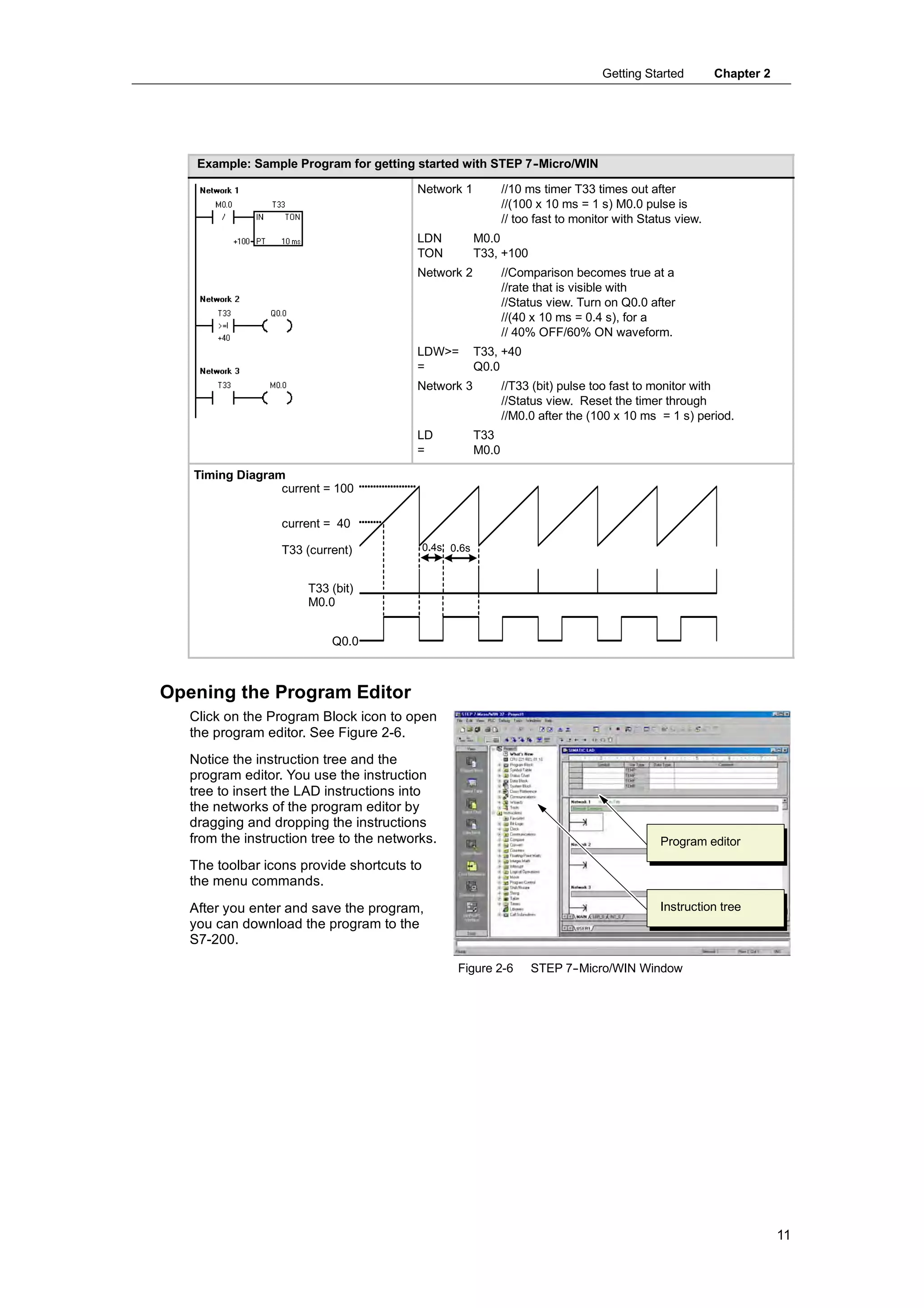
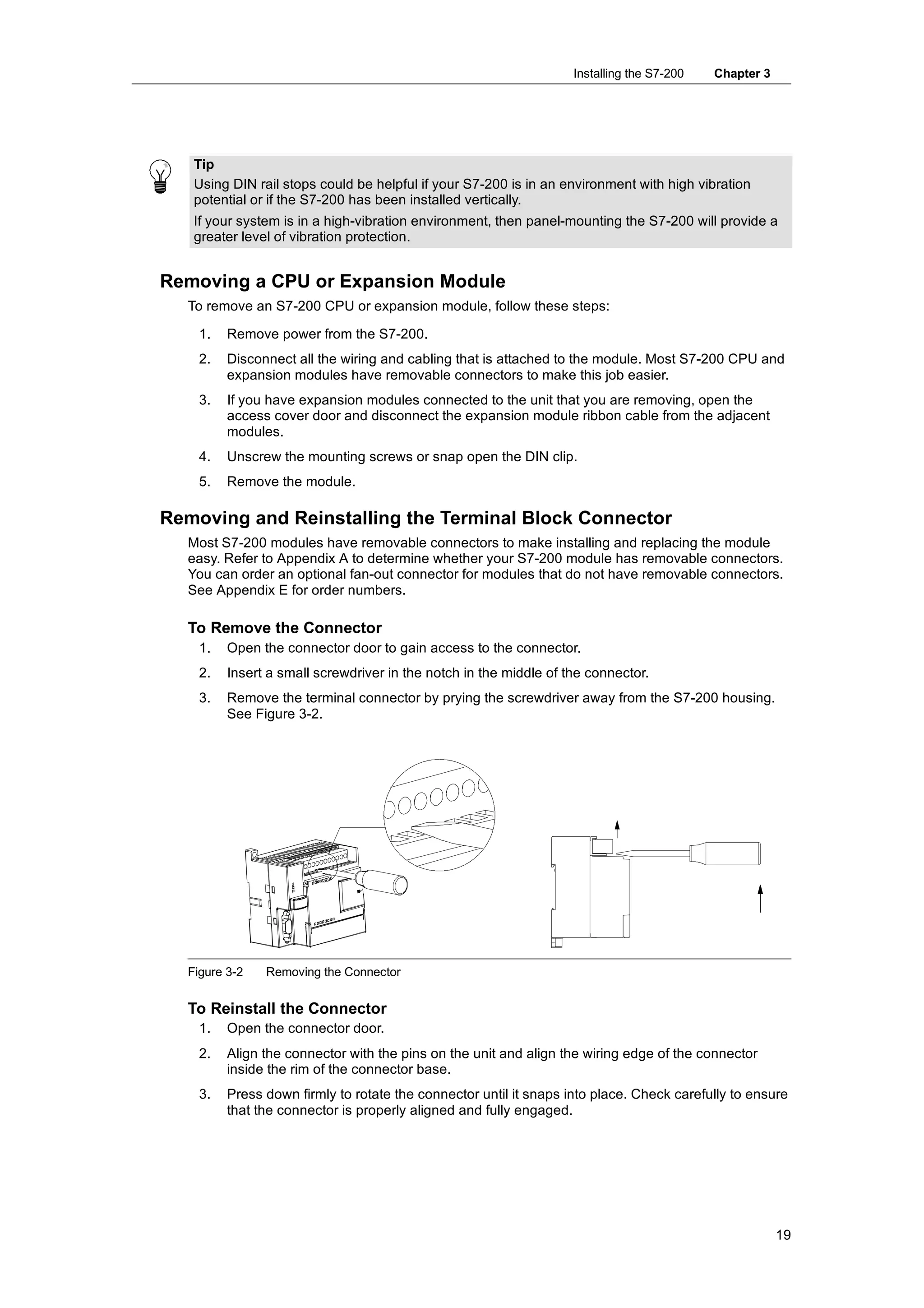
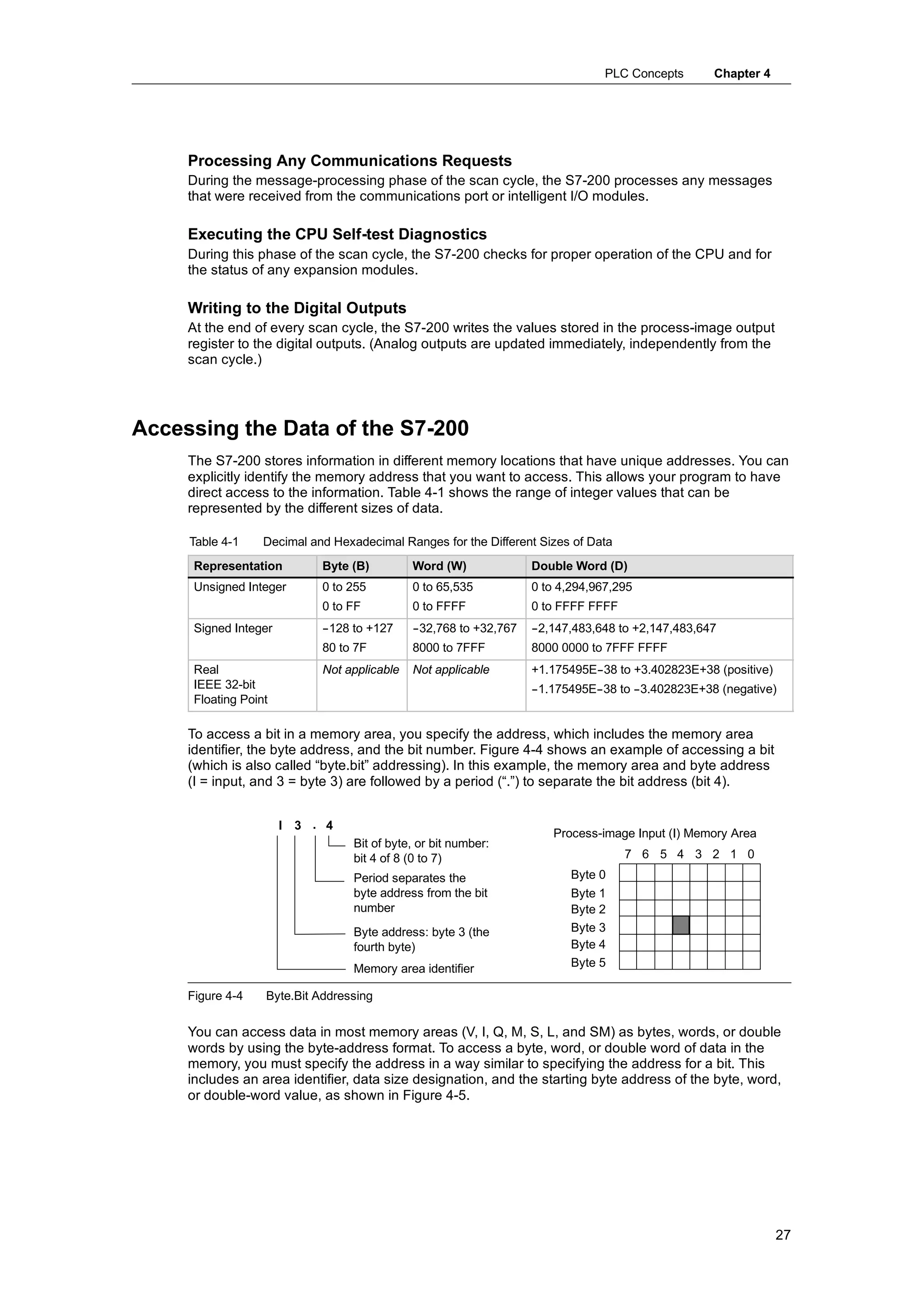
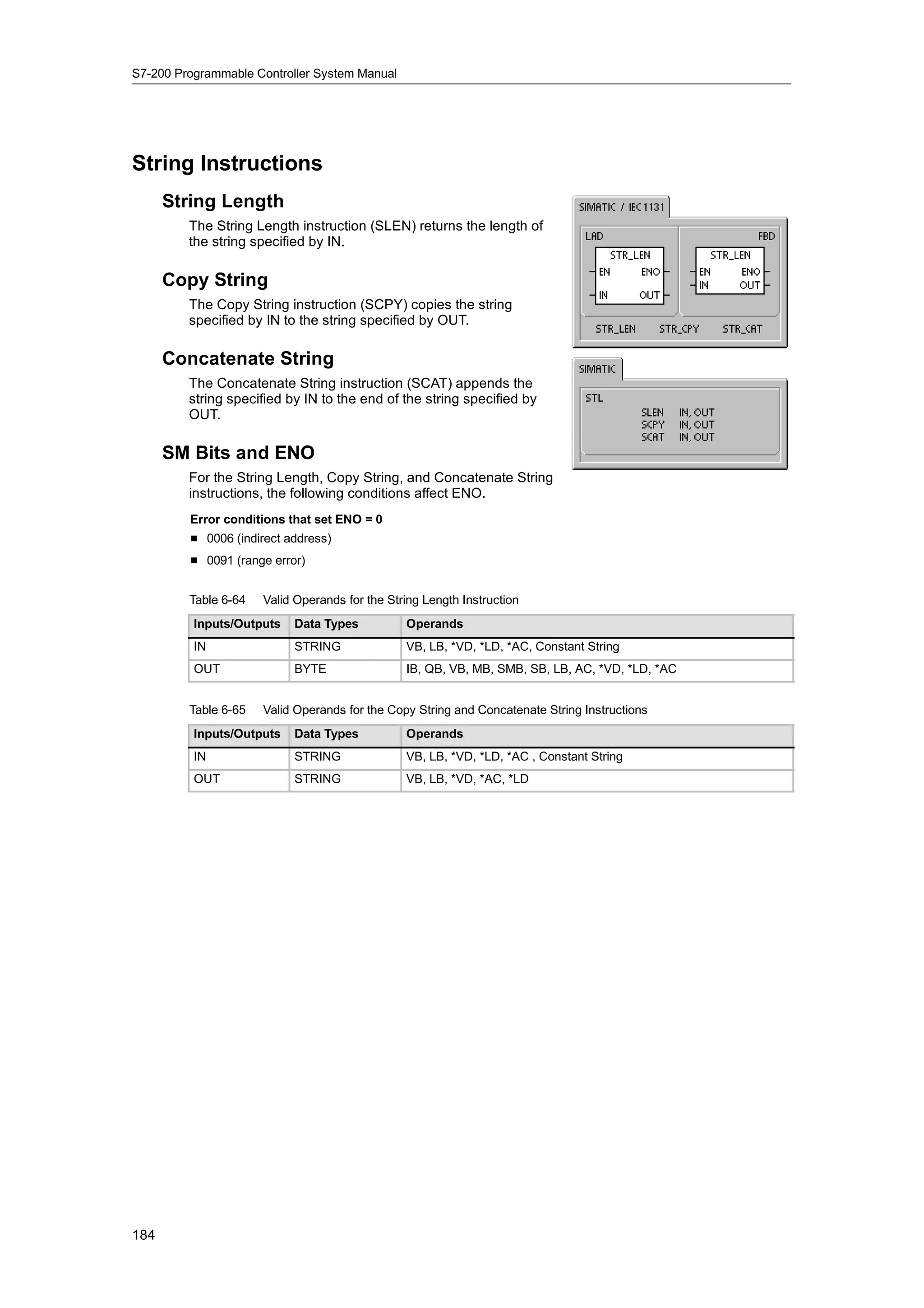
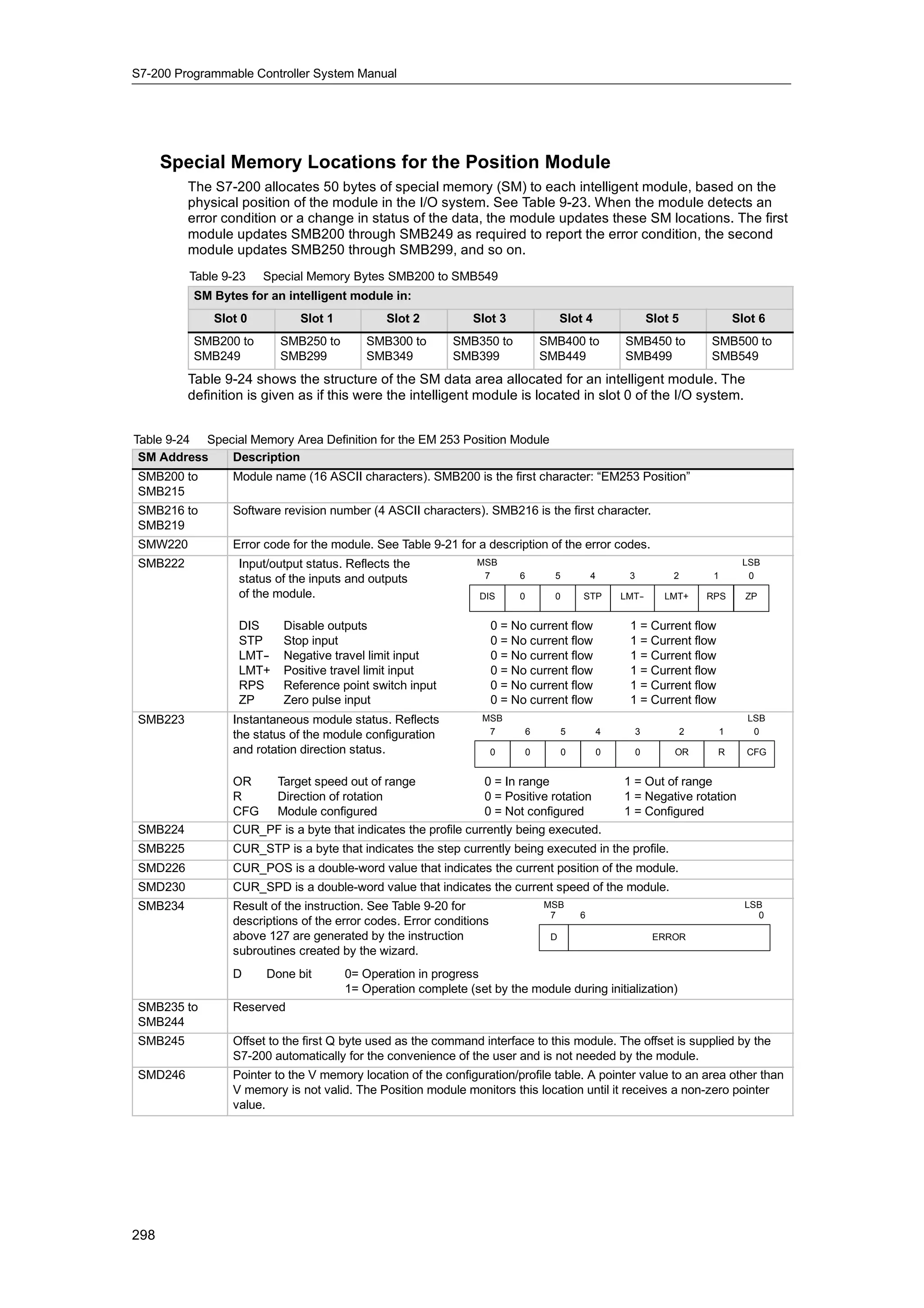
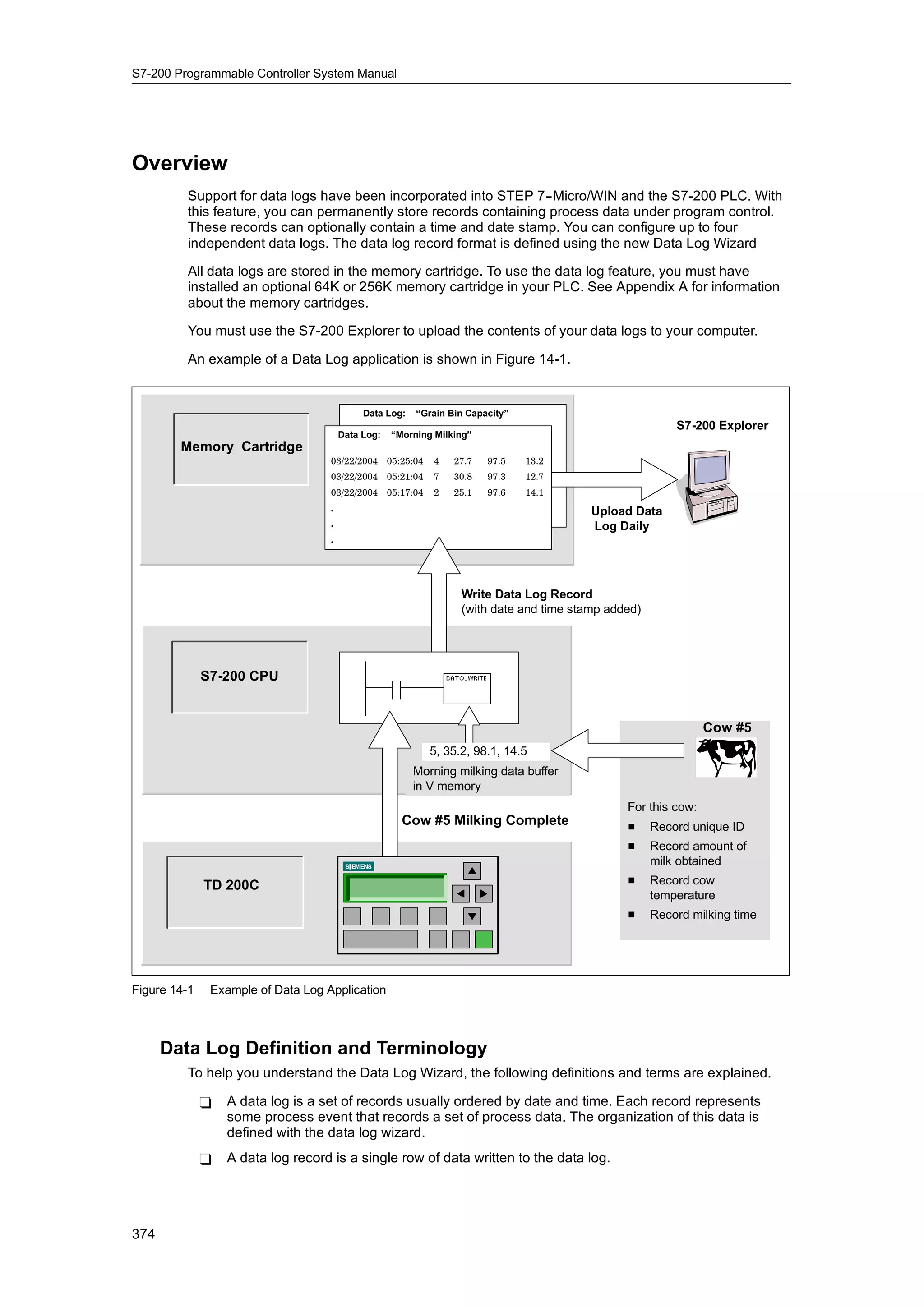
Accessing Data in the Memory Areas
Process-Image Input Register: I
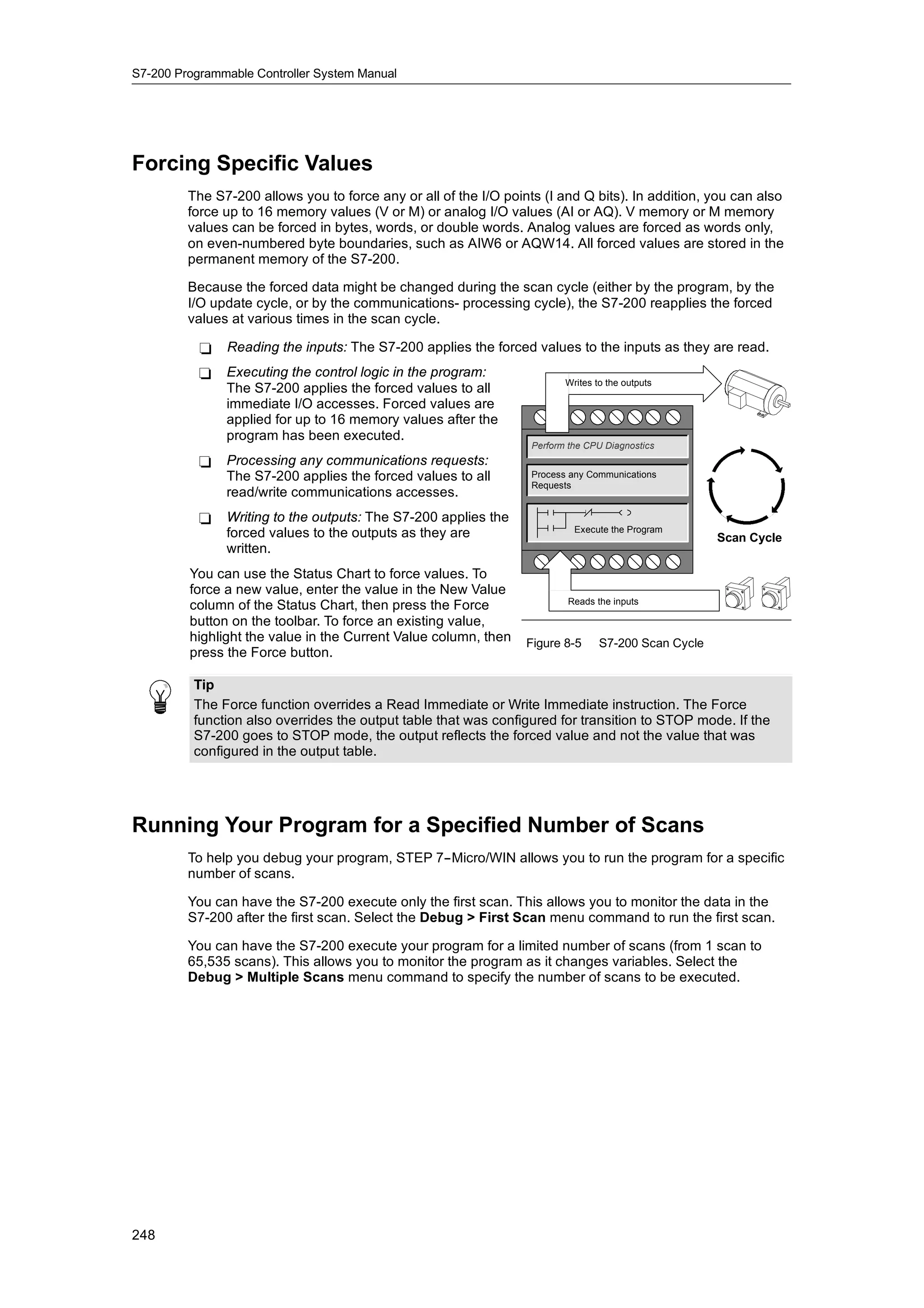
The S7-200 samples the physical input points at the beginning of each scan cycle and writes
these values to the process-image input register. You can access the process-image input register
in bits, bytes, words, or double words:
Bit: I[byte address].[bit address] I0.1
Byte, Word, or Double Word: I[size][starting byte address] IB4
Process-Image Output Register: Q
At the end of the scan cycle, the S7-200 copies the values stored in the process-image output
register to the physical output points. You can access the process-image output register in bits,
bytes, words, or double words:
Bit: Q[byte address].[bit address] Q1.1
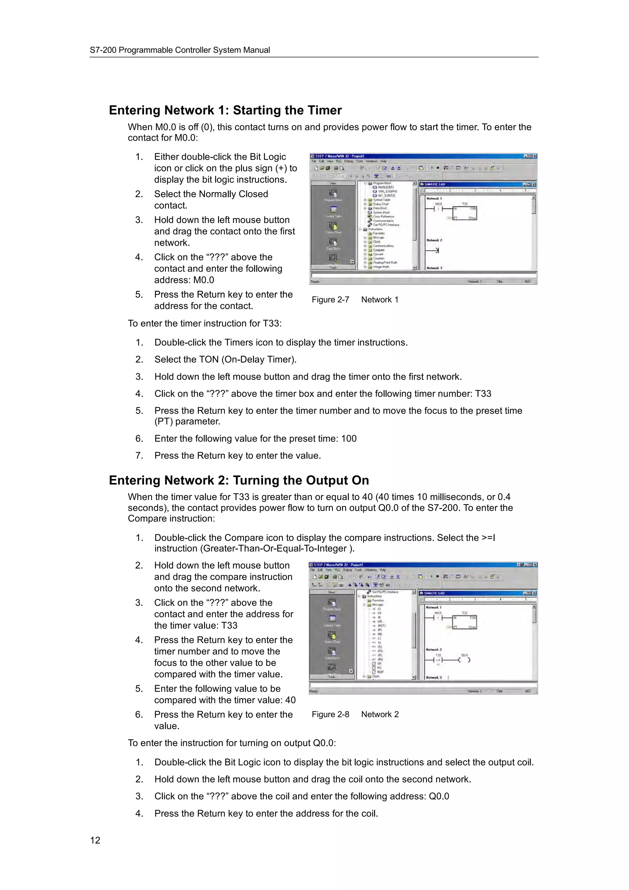
Byte, Word, or Double Word: Q[size][starting byte address] QB5
Variable Memory Area: V
You can use V memory to store intermediate results of operations being performed by the control
logic in your program. You can also use V memory to store other data pertaining to your process
or task. You can access the V memory area in bits, bytes, words, or double words:
Bit: V[byte address].[bit address] V10.2
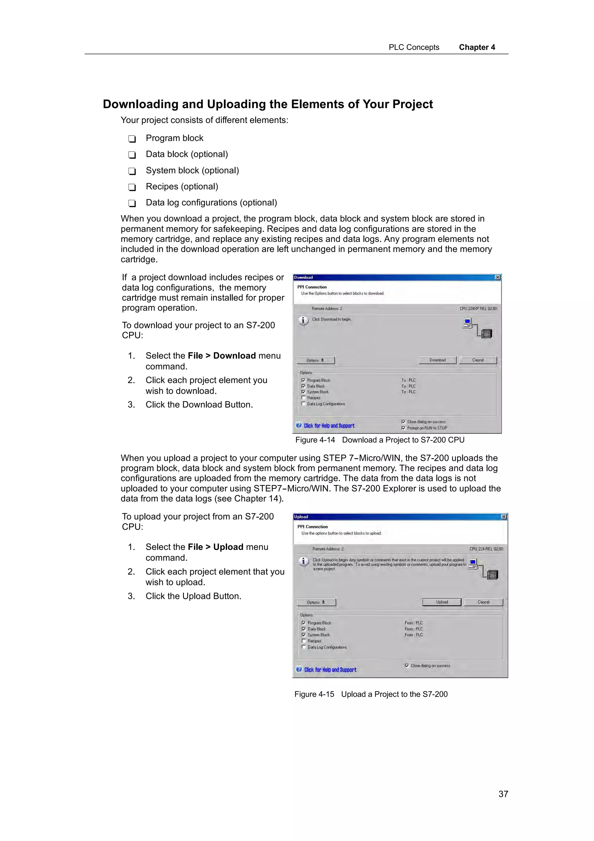
Byte, Word, or Double Word: V[size][starting byte address] VW100
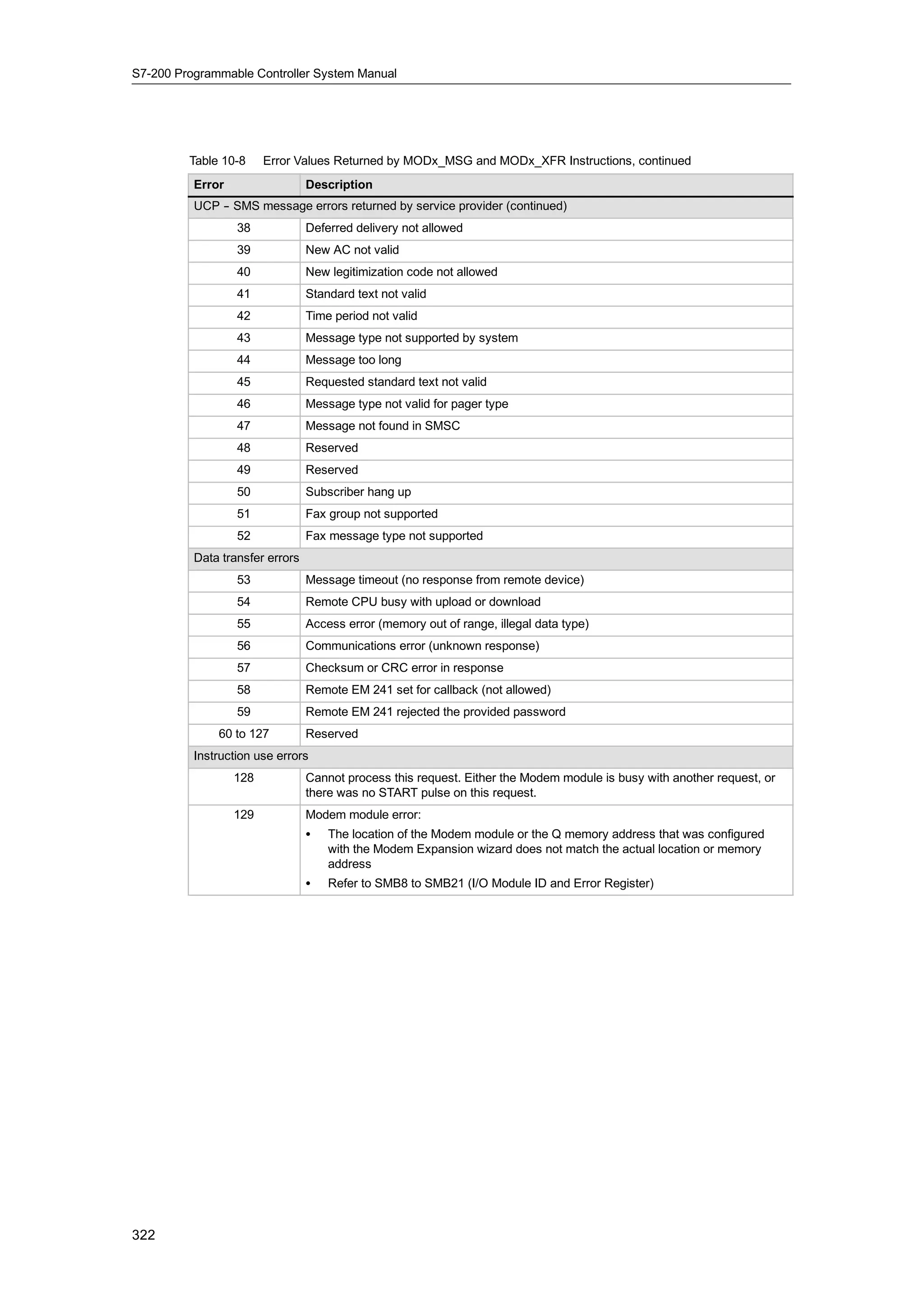
Bit Memory Area: M
You can use the bit memory area (M memory) as control relays to store the intermediate status of
an operation or other control information. You can access the bit memory area in bits, bytes,
words, or double words:
Bit: M[byte address].[bit address] M26.7
Byte, Word, or Double Word: M[size][starting byte address] MD20
28](https://image.slidesharecdn.com/s7200systemmanualen-us-121009044520-phpapp02/75/S72-00-system-manual_en-us-42-2048.jpg)
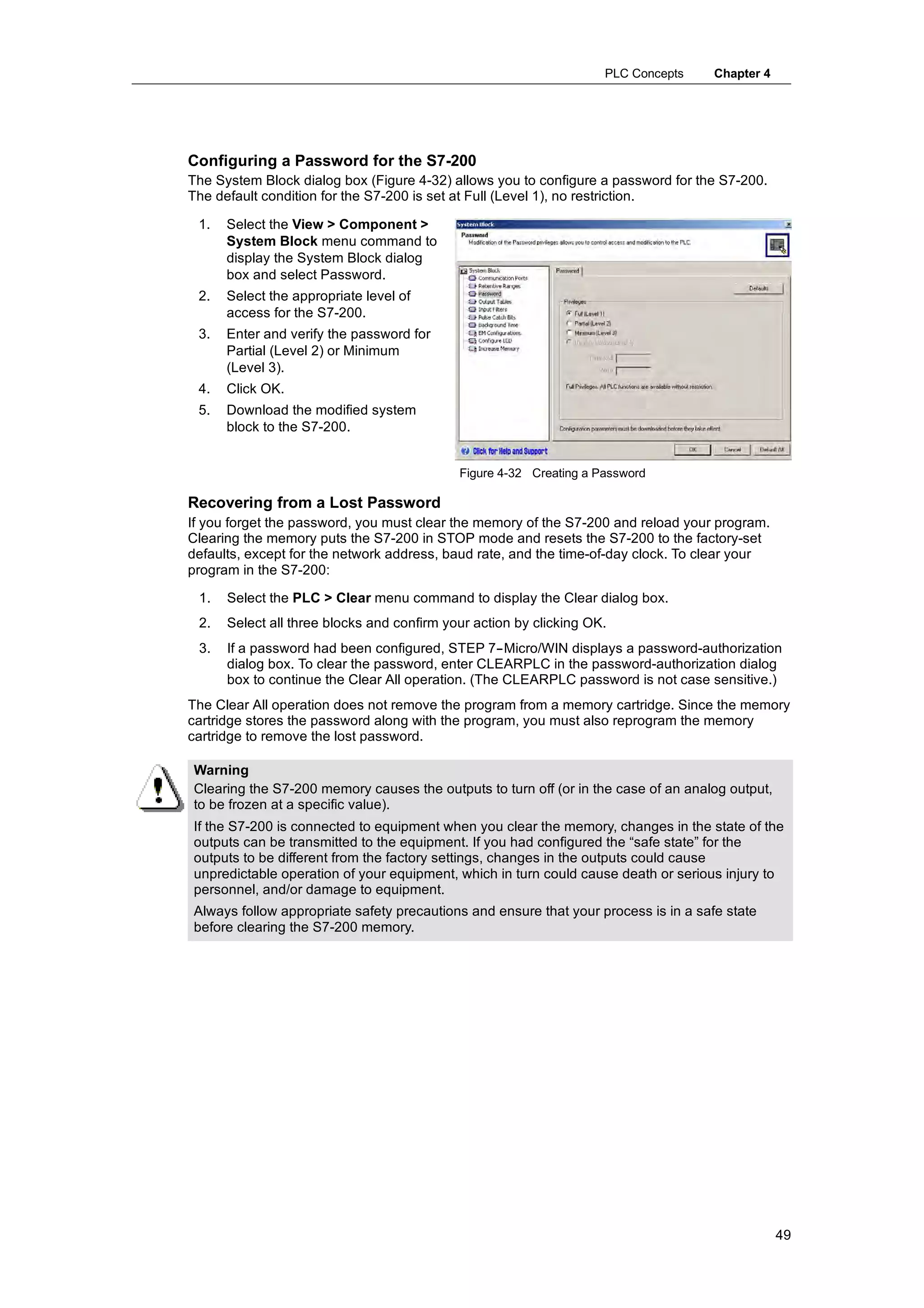
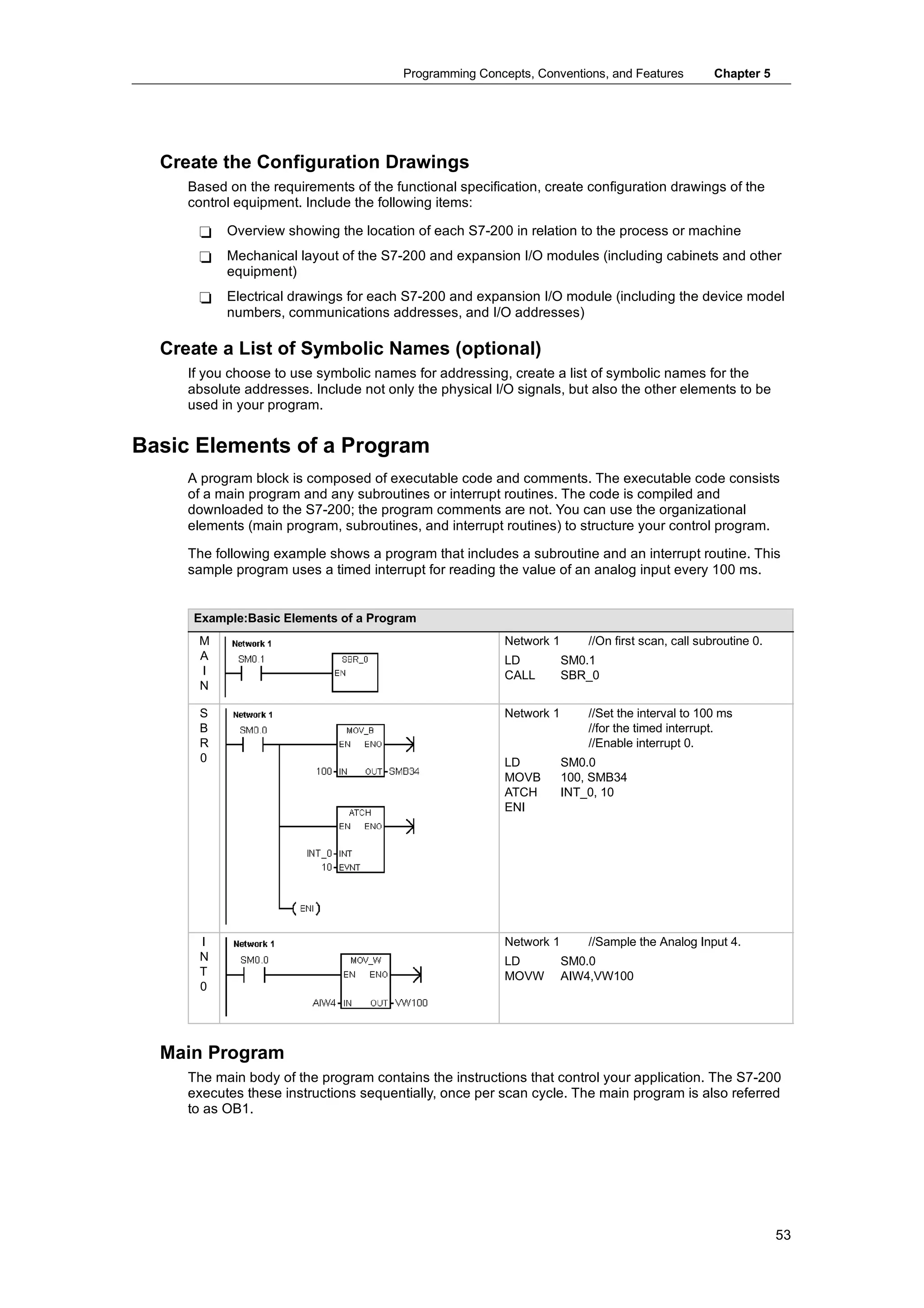
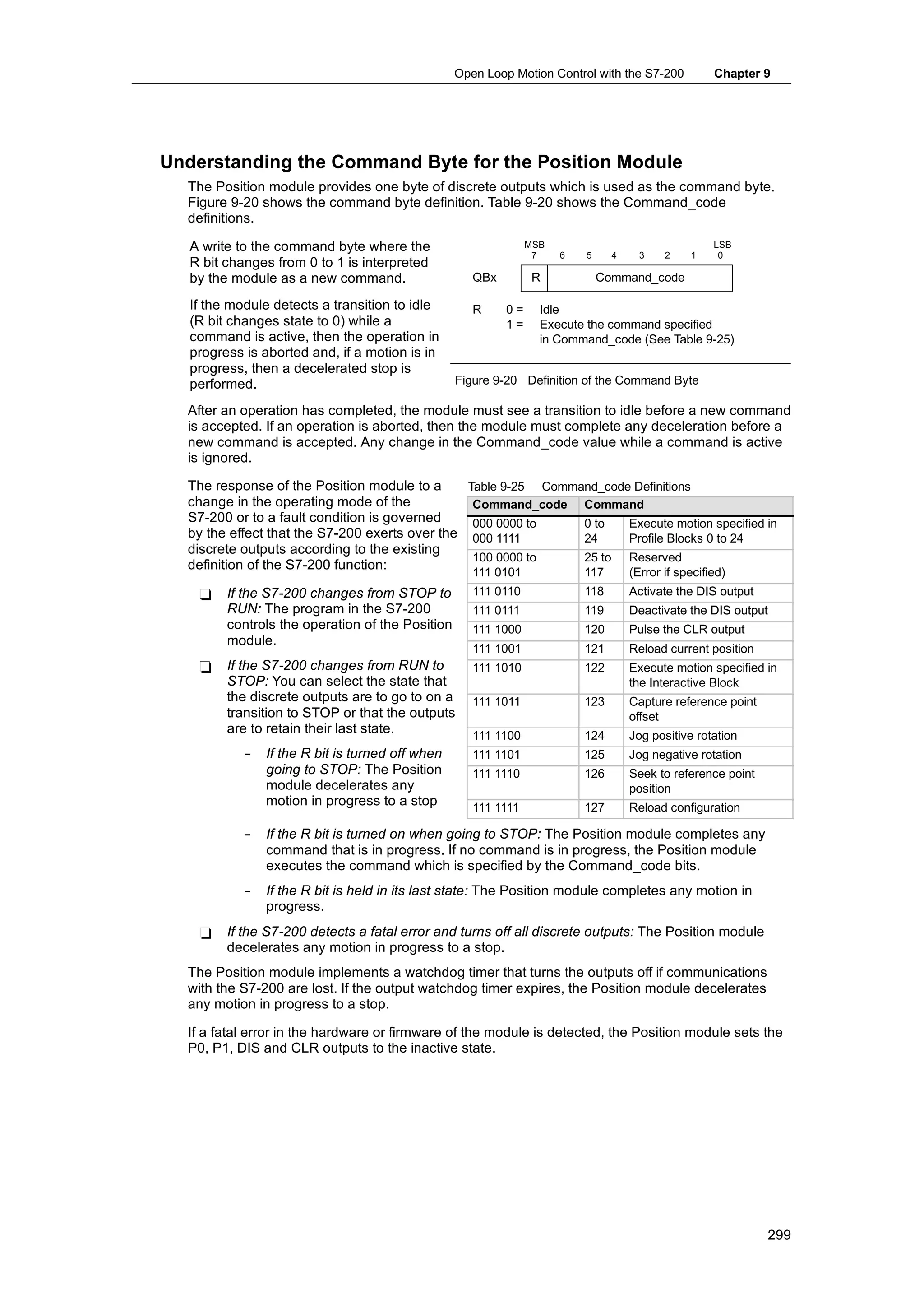
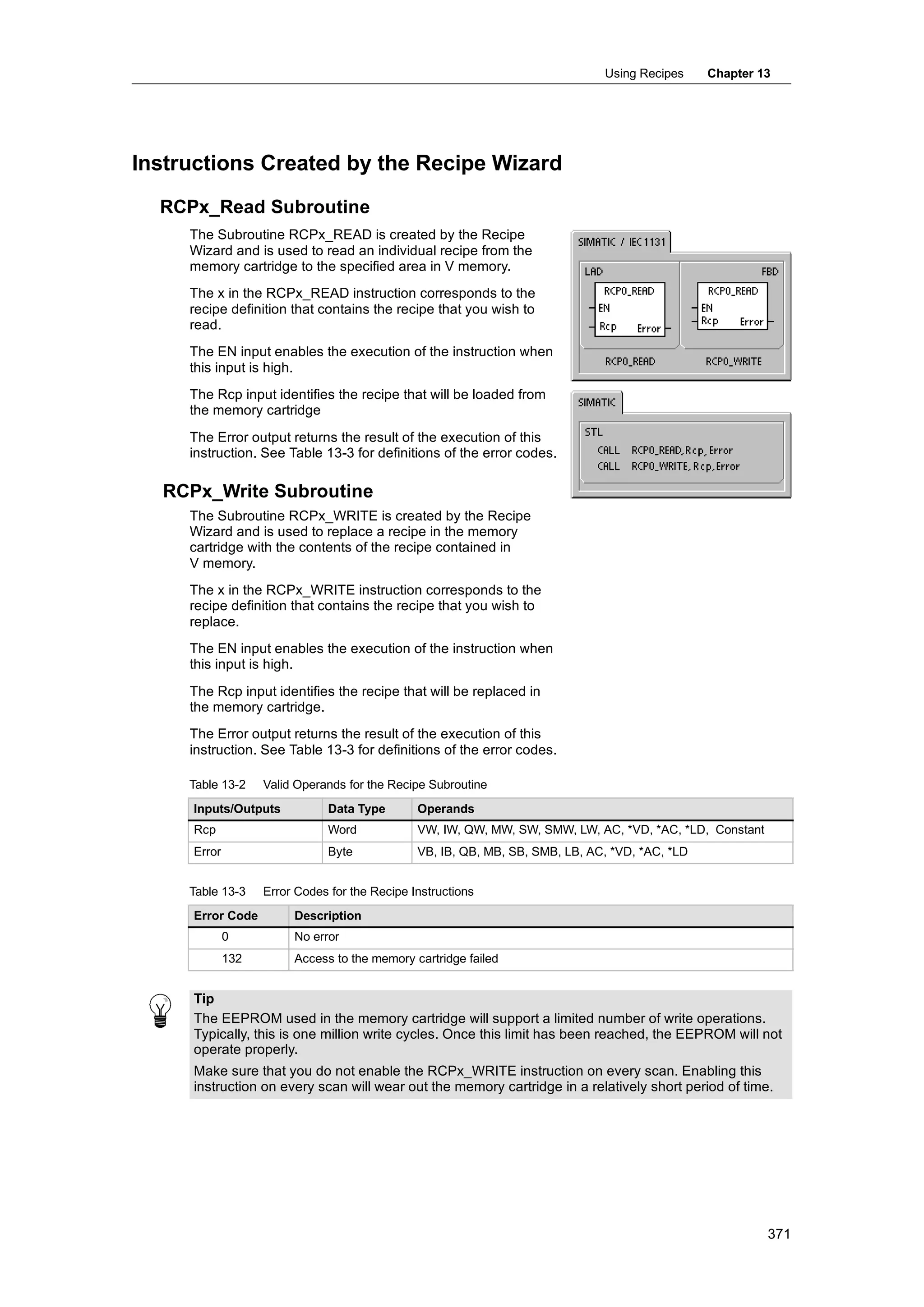
![PLC Concepts Chapter 4
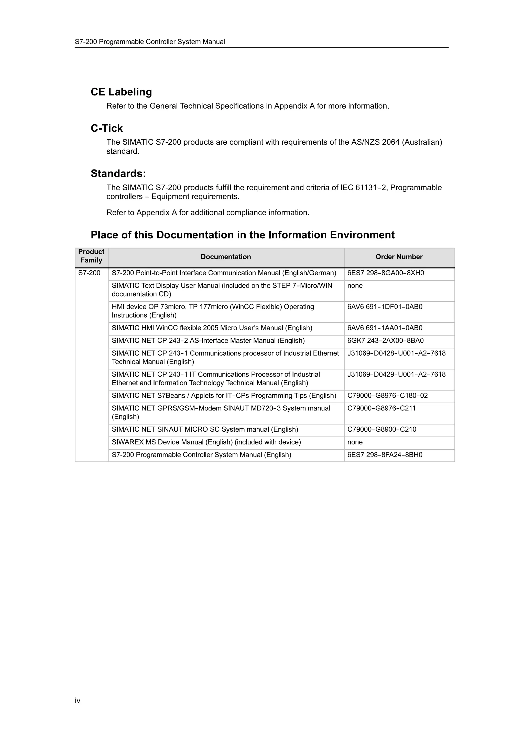
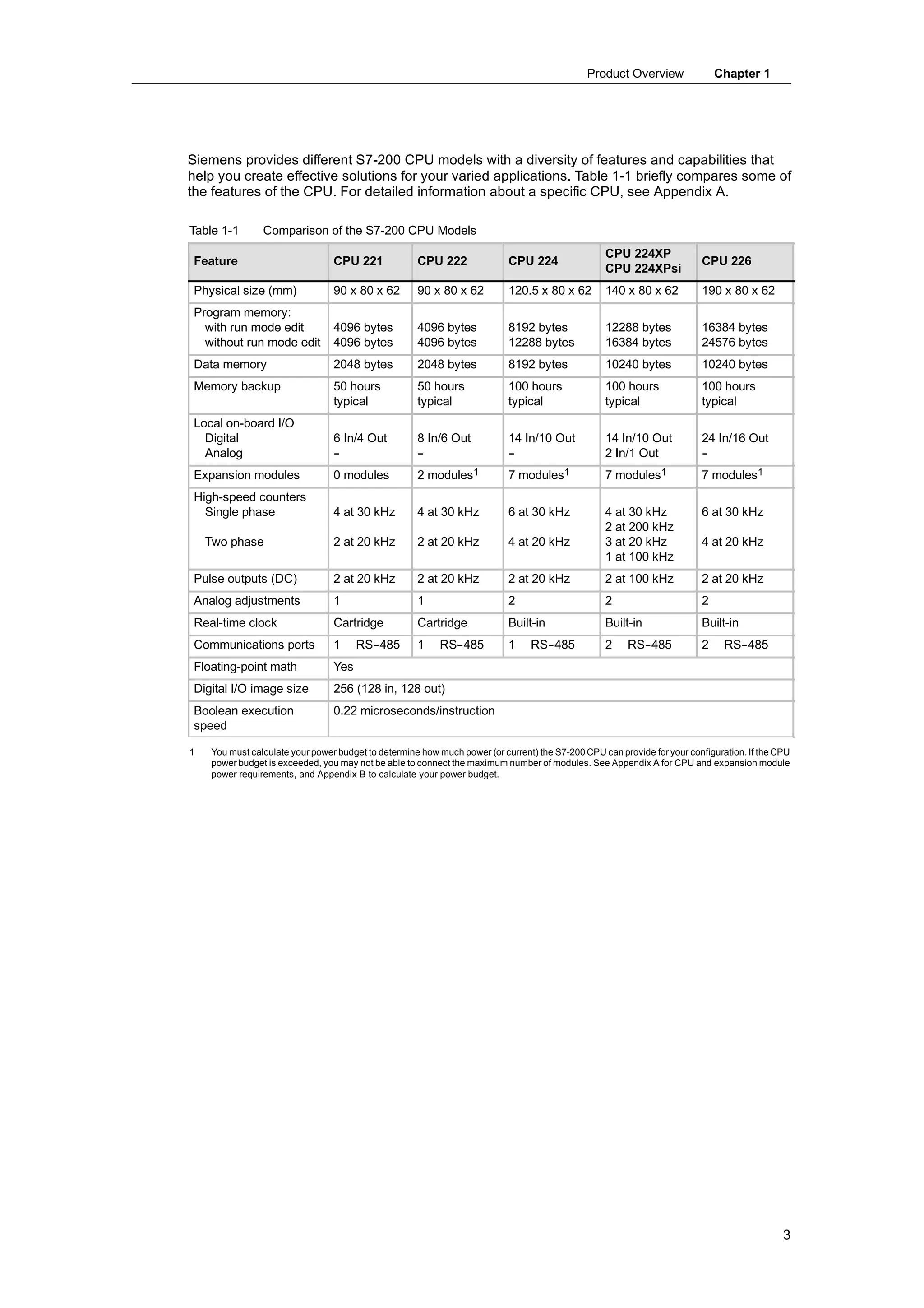
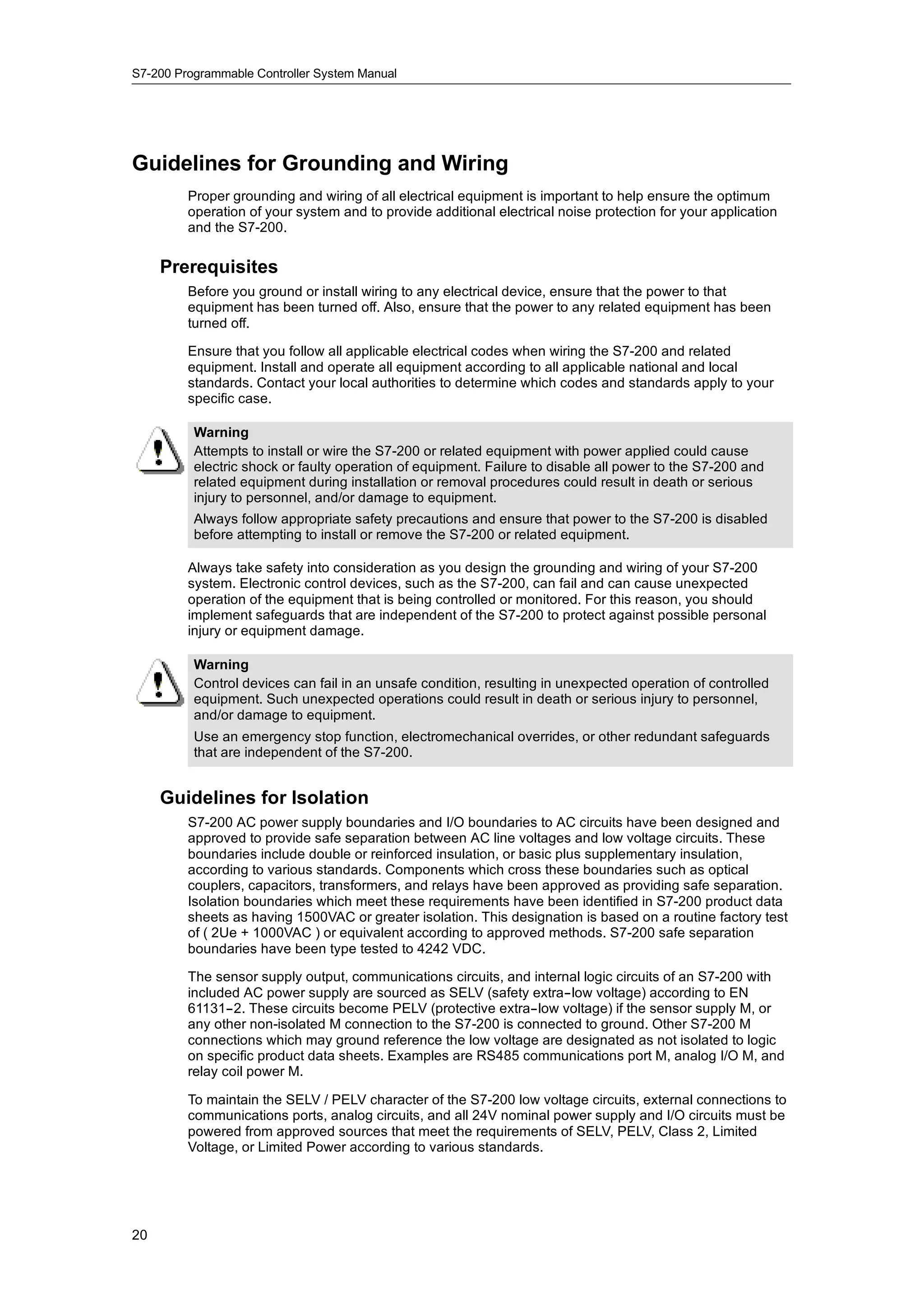
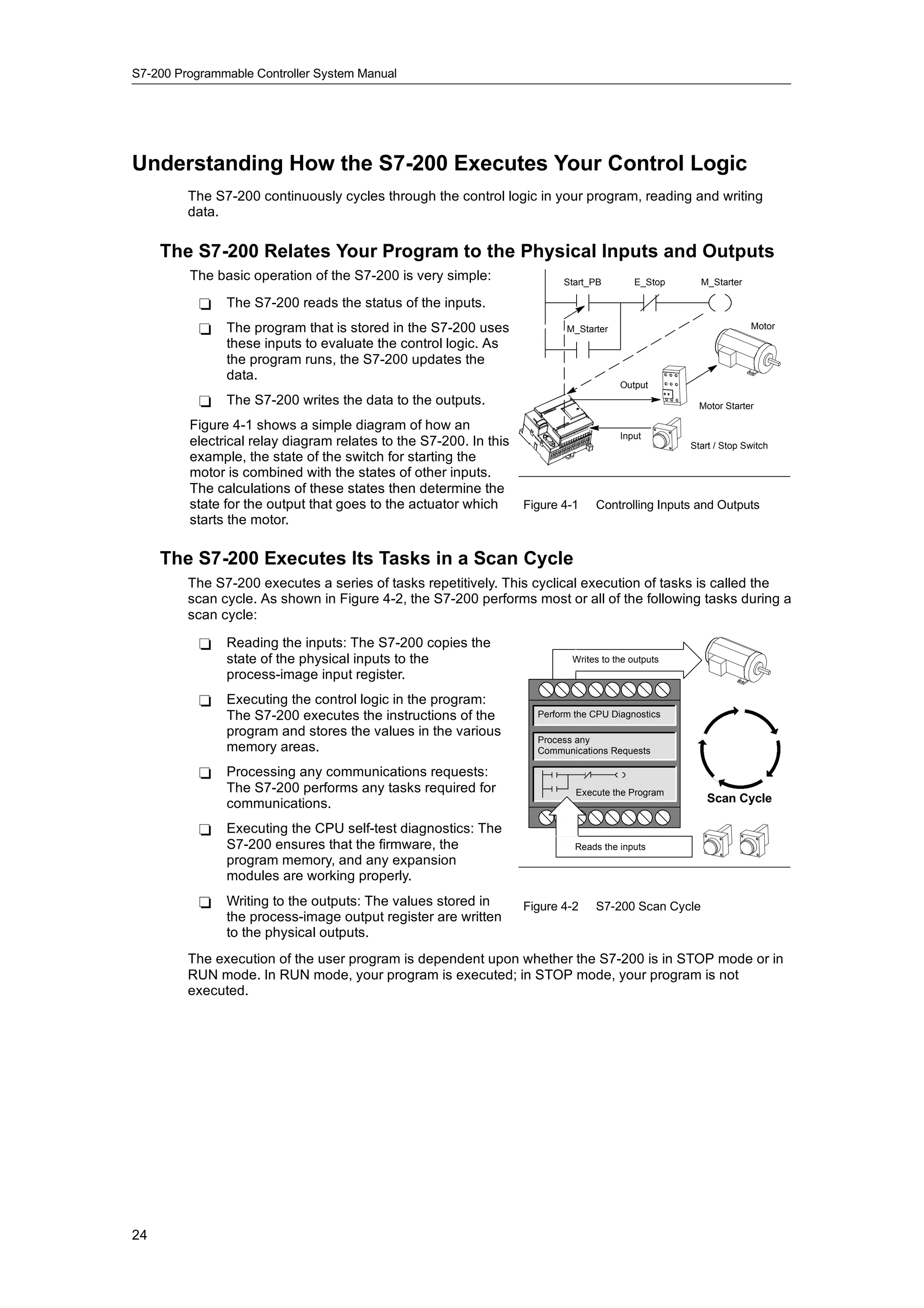
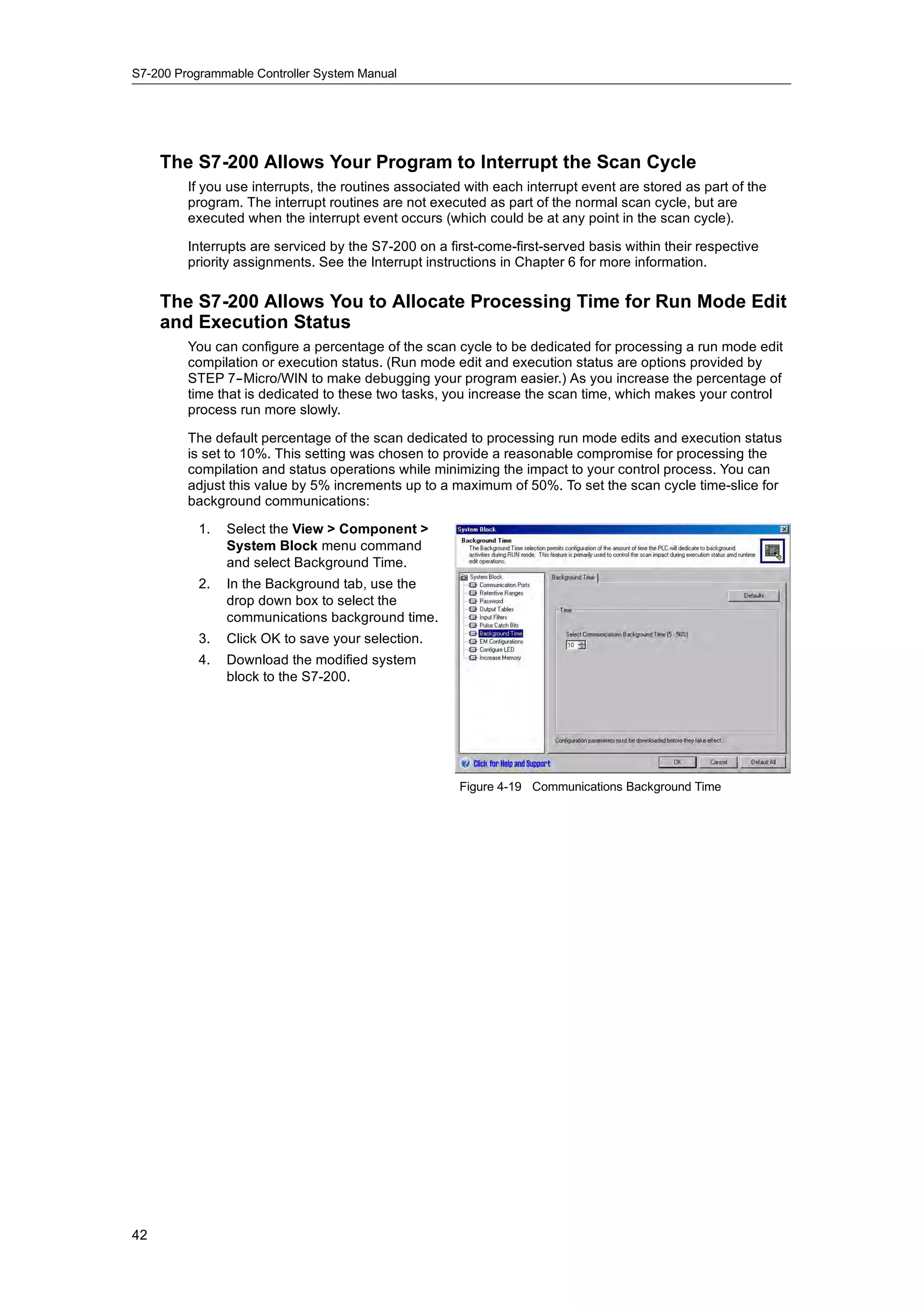
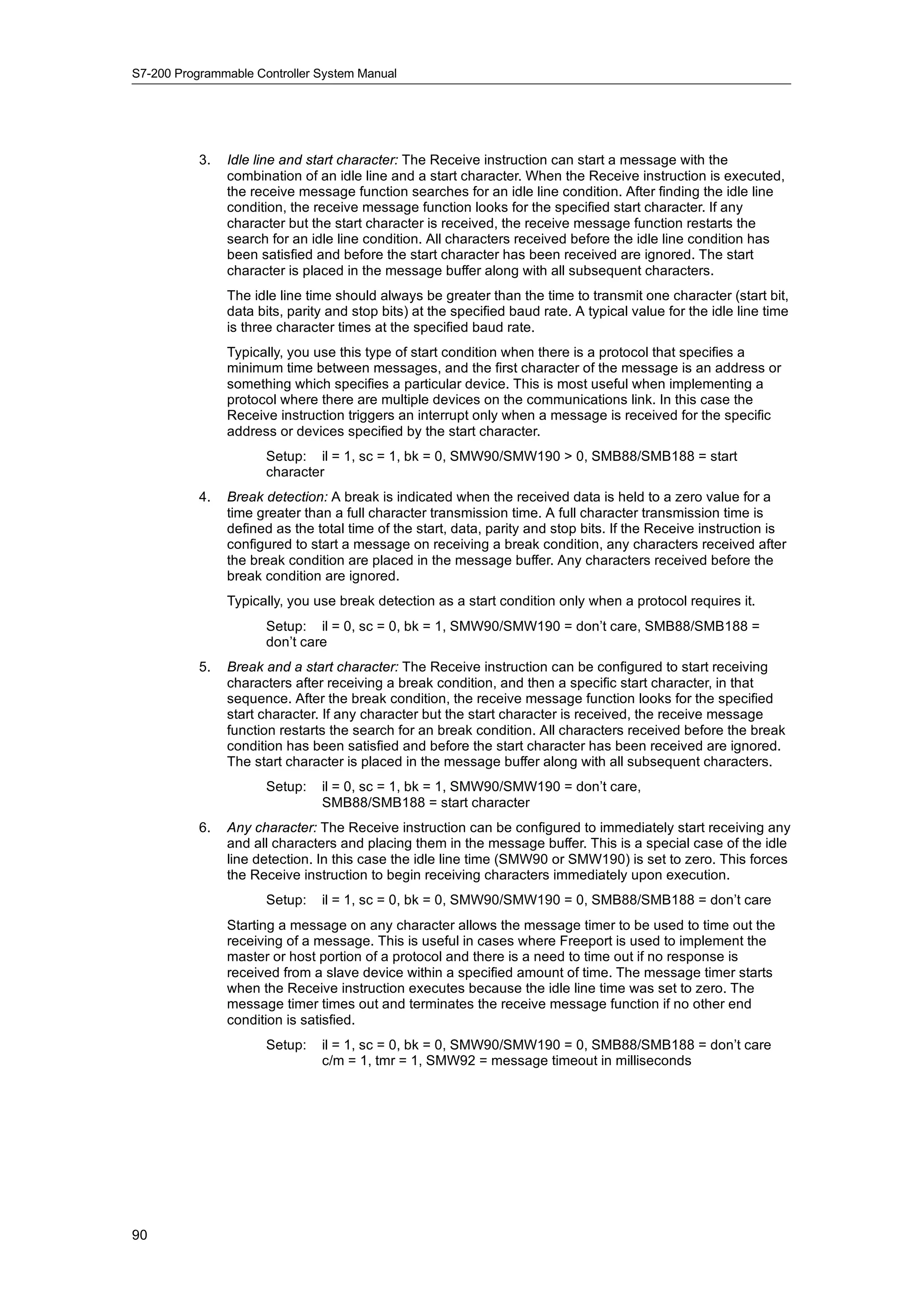
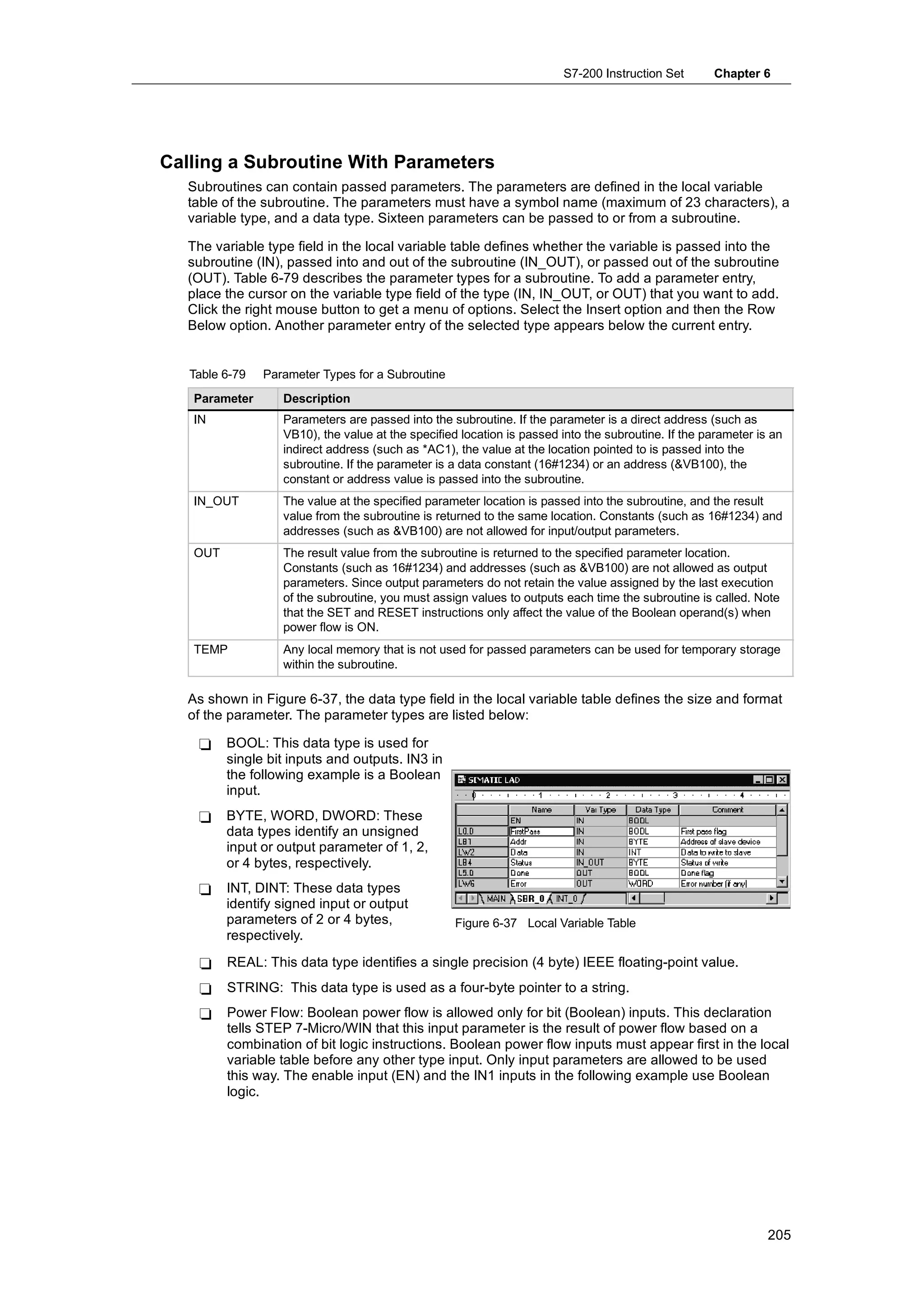
Timer Memory Area: T
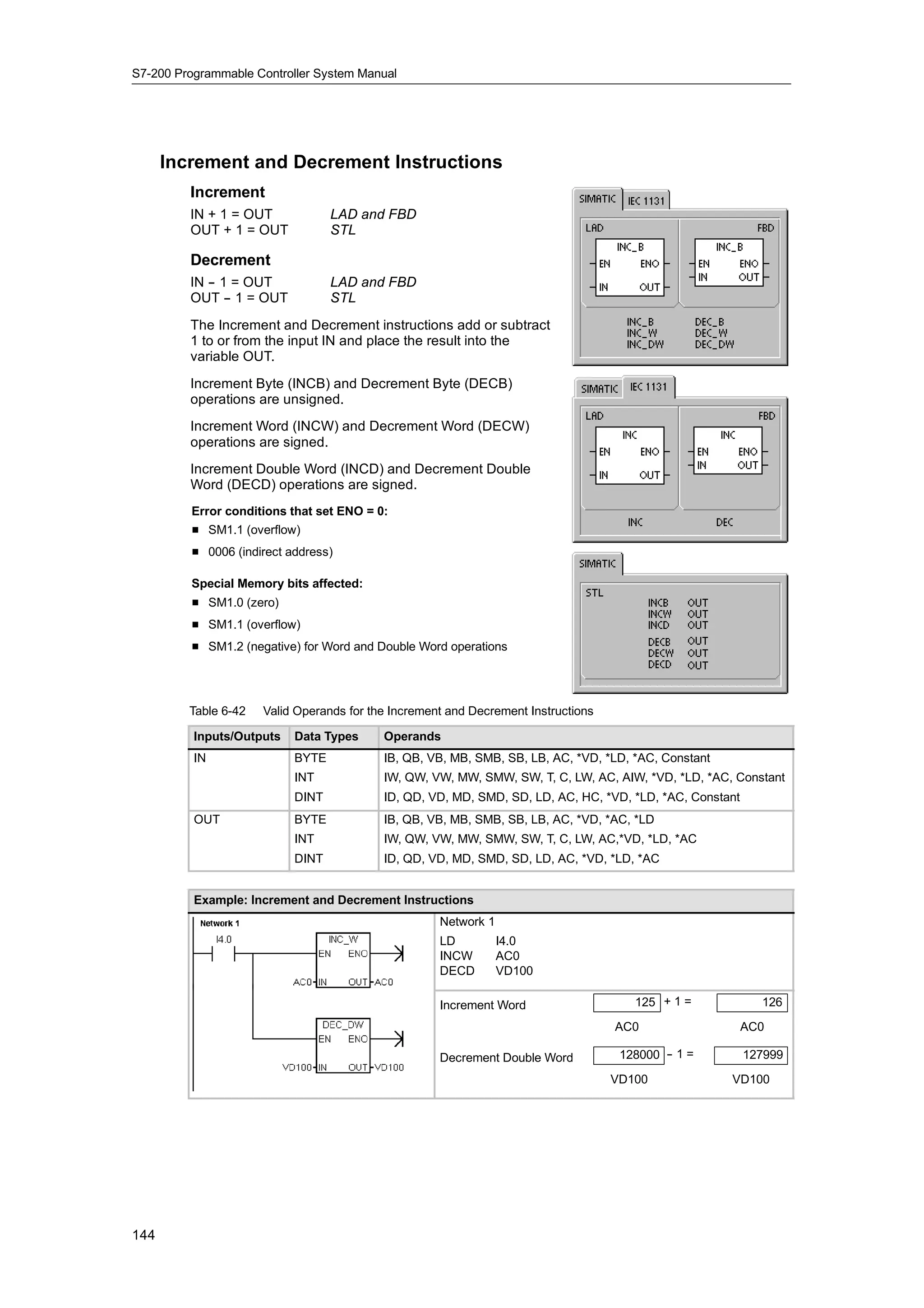
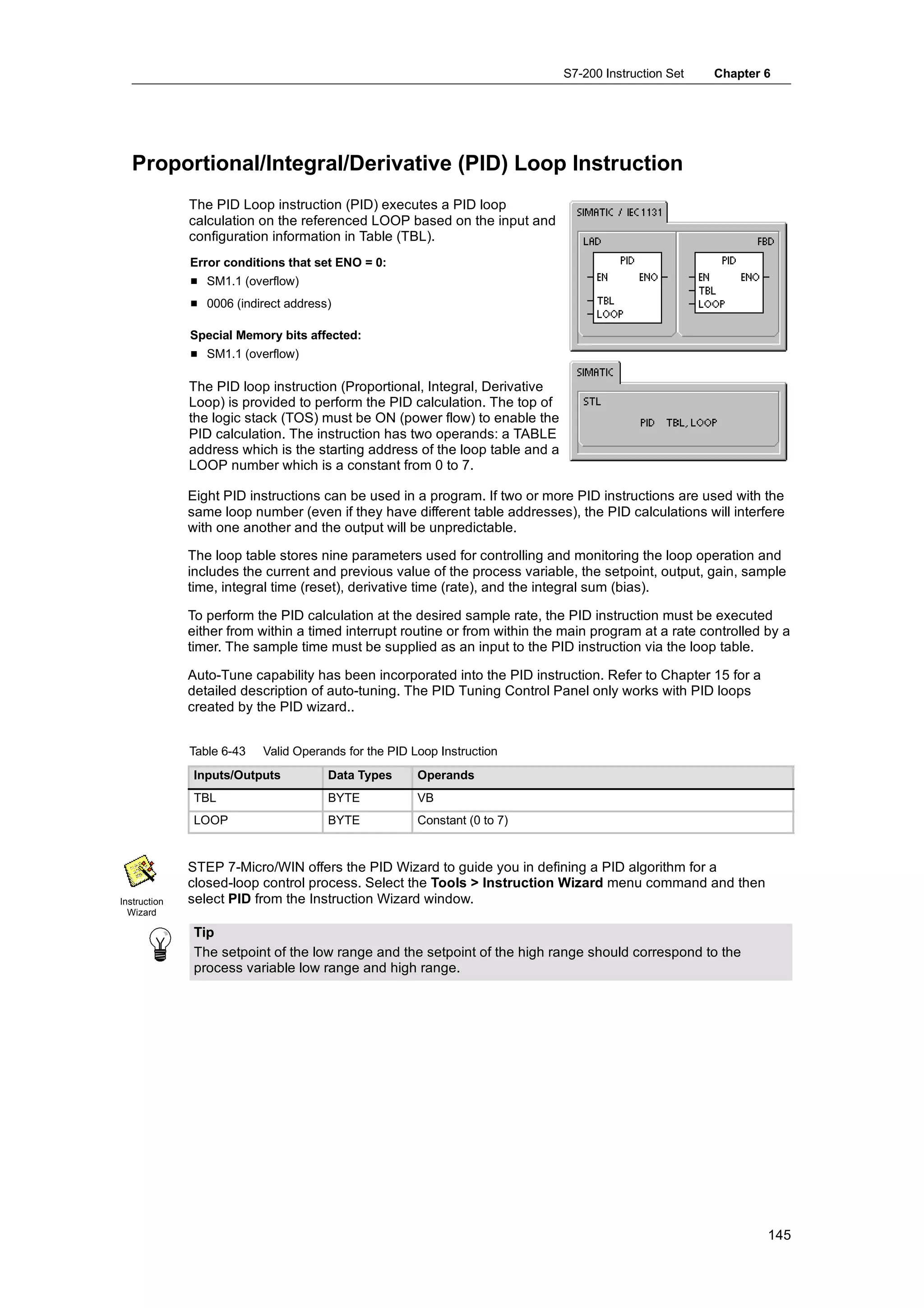
The S7-200 provides timers that count increments of time in resolutions (time-base increments) of
1 ms, 10 ms, or 100 ms. Two variables are associated with a timer:
- Current value: this 16-bit signed integer stores the amount of time counted by the timer.
- Timer bit: this bit is set or cleared as a result of comparing the current and the preset value.
The preset value is entered as part of the timer instruction.
You access both of these variables by using the timer address (T + timer number). Access to
either the timer bit or the current value is dependent on the instruction used: instructions with bit
operands access the timer bit, while instructions with word operands access the current value. As
shown in Figure 4-6, the Normally Open Contact instruction accesses the timer bit, while the Move
Word instruction accesses the current value of the timer.
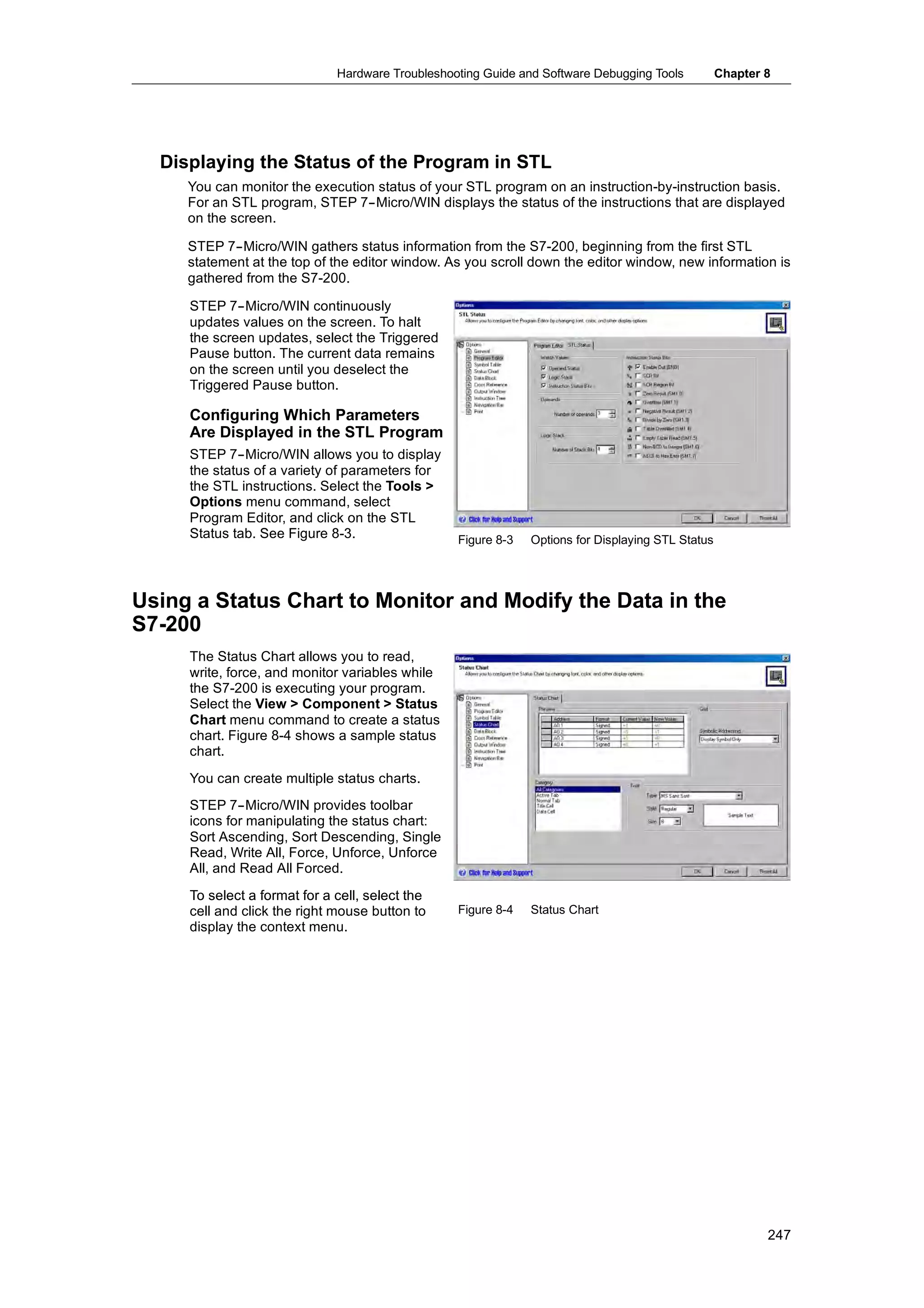
Format: T[timer number] T24
I2.1 MOV_ T3
Current Value Timer Bits
EN W
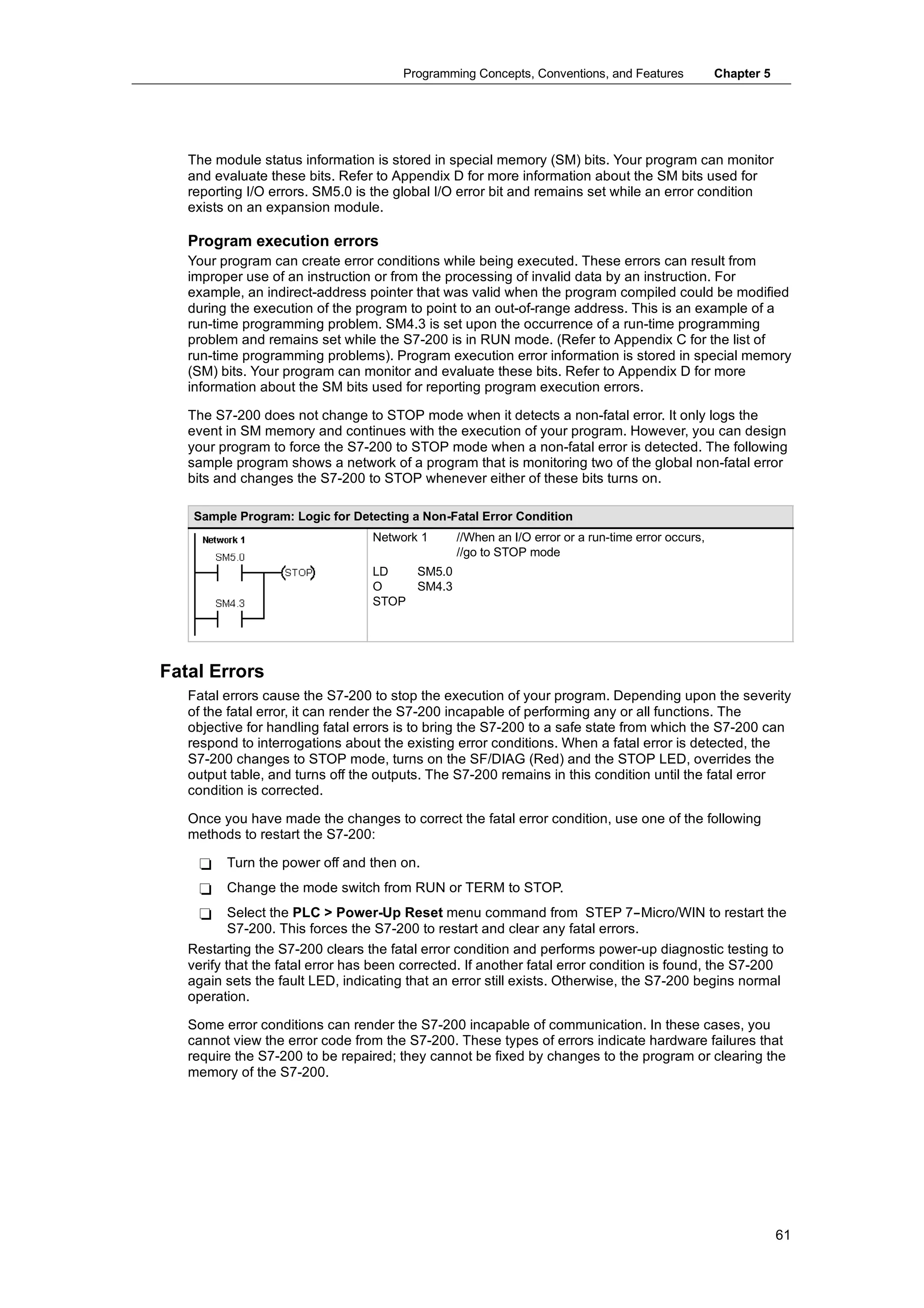
T0 T0
T3 IN OUT VW200
T1 T1
T2 T2
15 (MSB) T3 0 (LSB) T3
Accesses the current value
Accesses the timer bit
Figure 4-6 Accessing the Timer Bit or the Current Value of a Timer
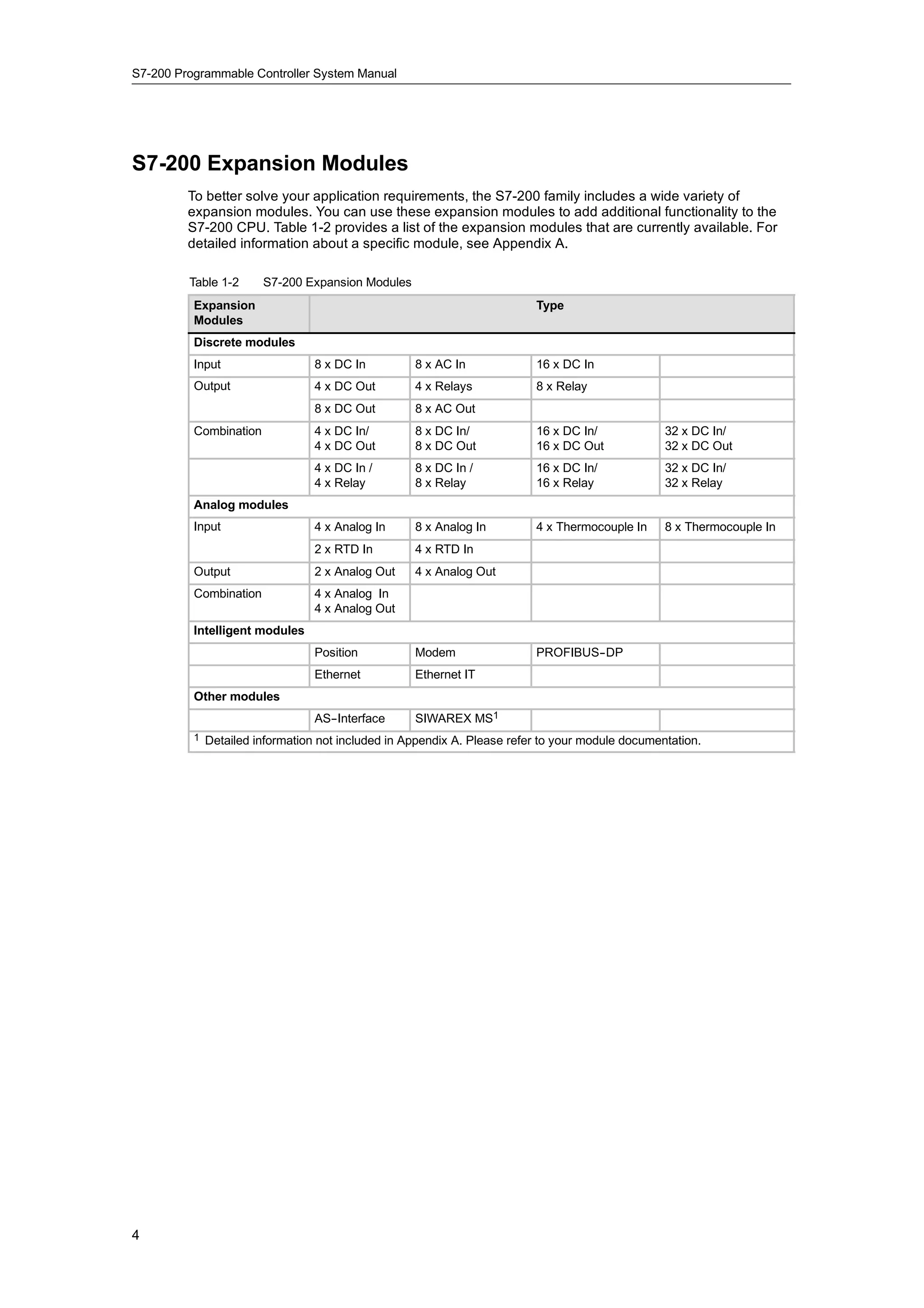
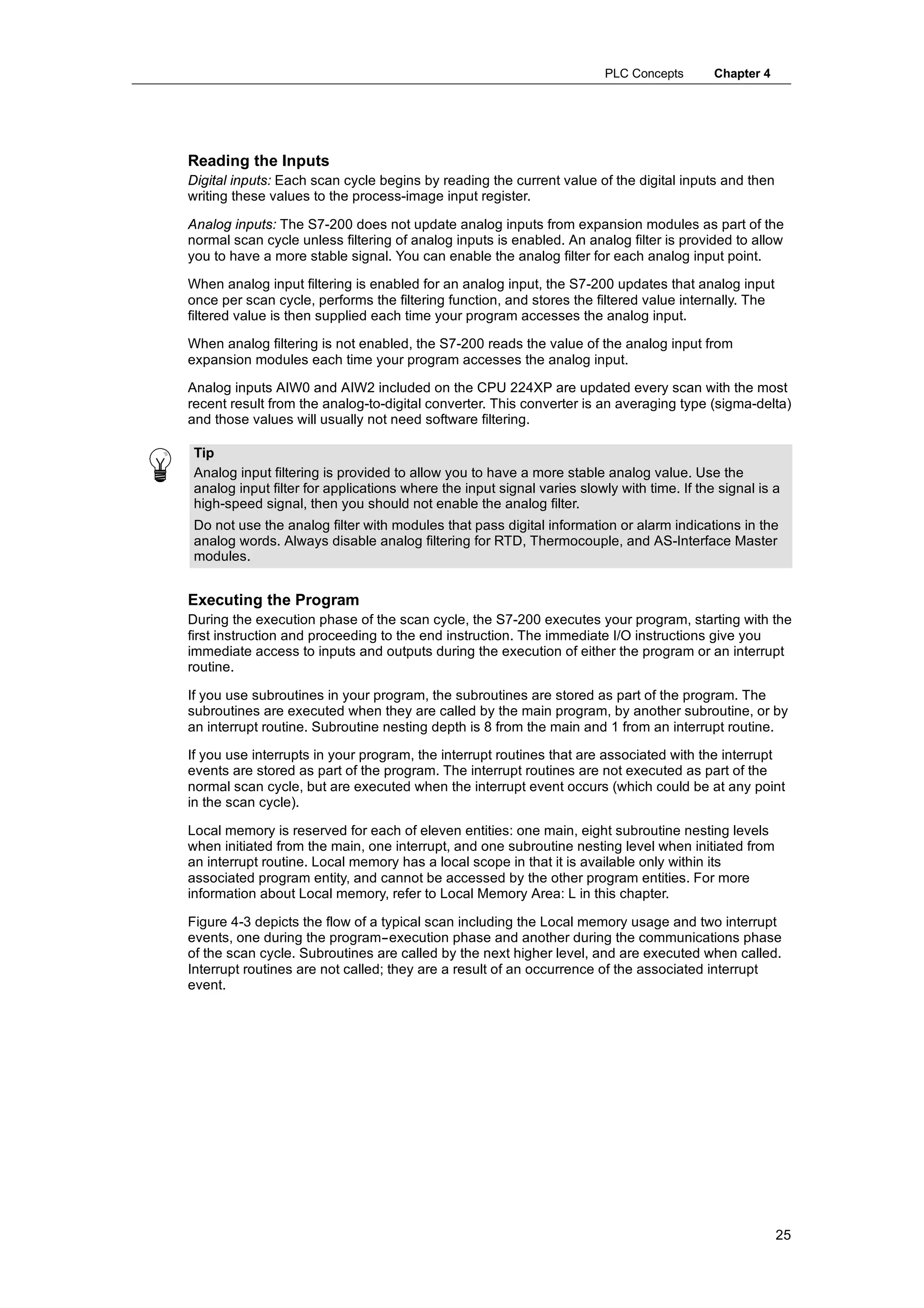
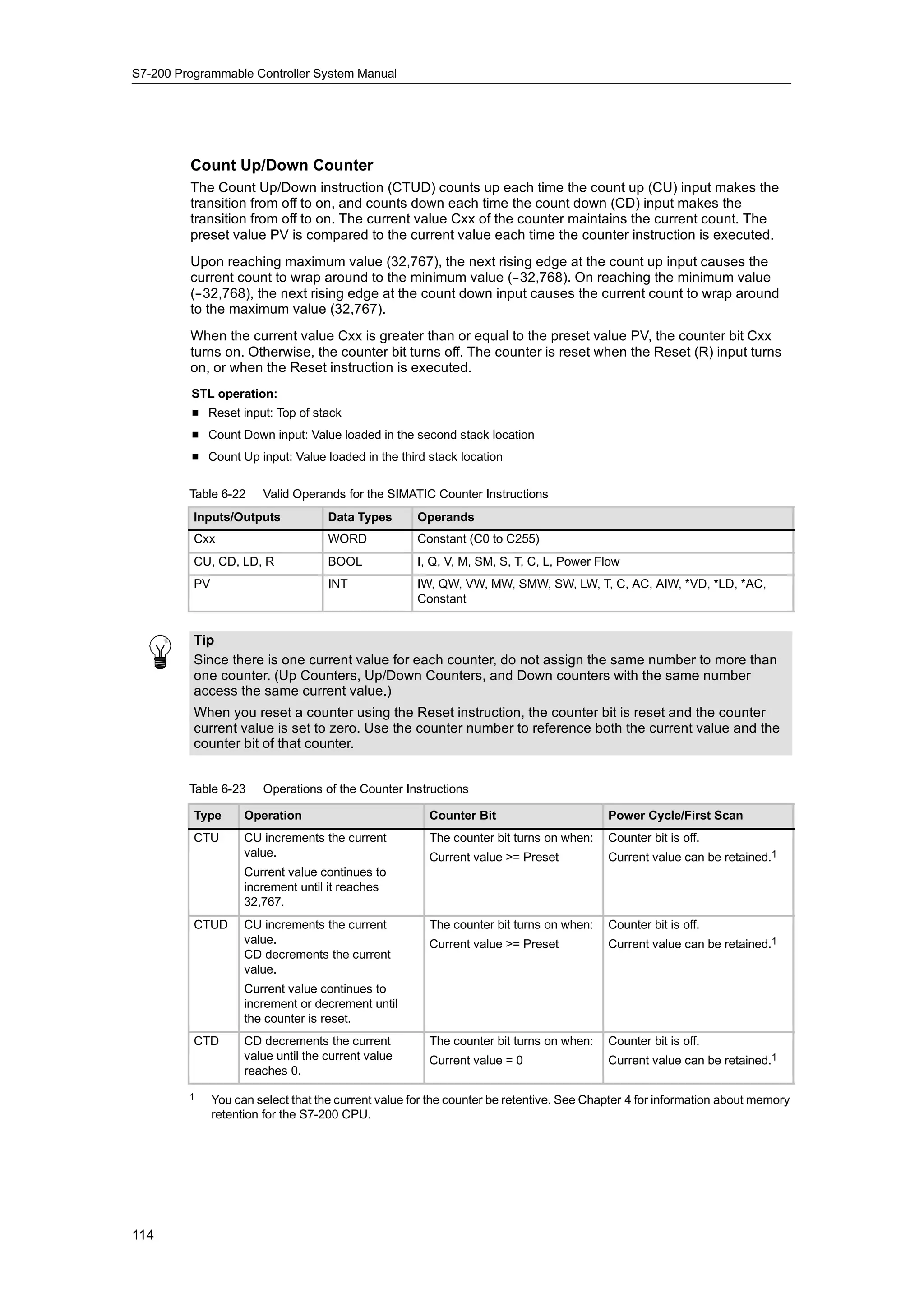
Counter Memory Area: C
The S7-200 provides three types of counters that count each low-to-high transition event on the
counter input(s): one type counts up only, one type counts down only, and one type counts both
up and down. Two variables are associated with a counter:
- Current value: this 16-bit signed integer stores the accumulated count.
- Counter bit: this bit is set or cleared as a result of comparing the current and the preset
value. The preset value is entered as part of the counter instruction.
You access both of these variables by using the counter address (C + counter number). Access to
either the counter bit or the current value is dependent on the instruction used: instructions with bit
operands access the counter bit, while instructions with word operands access the current value.
As shown in Figure 4-7, the Normally Open Contact instruction accesses the counter bit, while the
Move Word instruction accesses the current value of the counter.
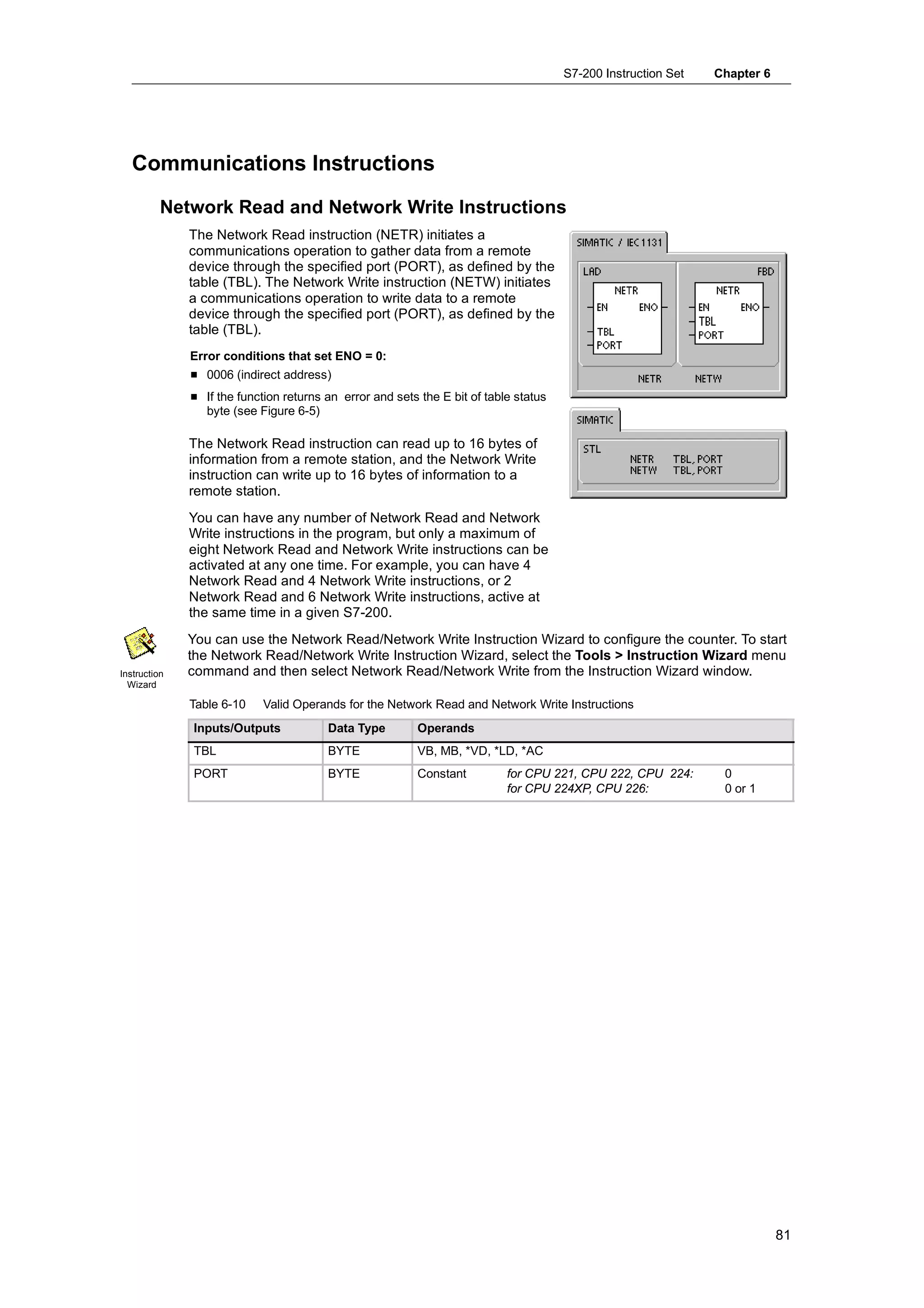
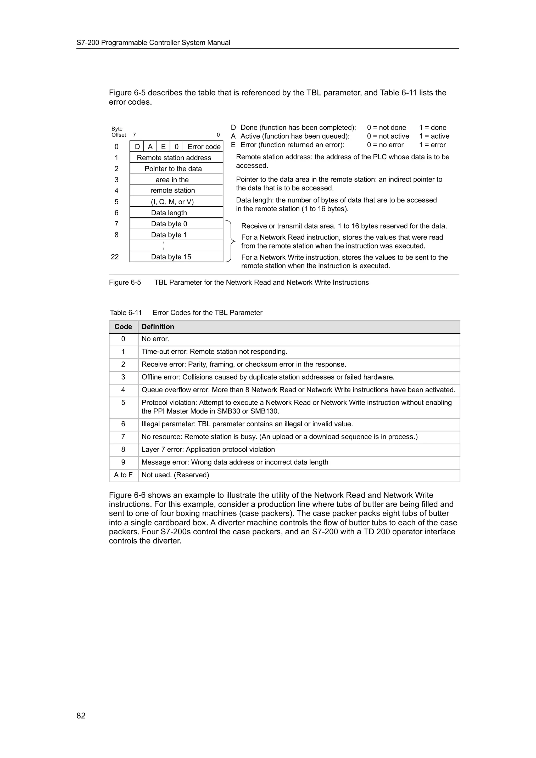
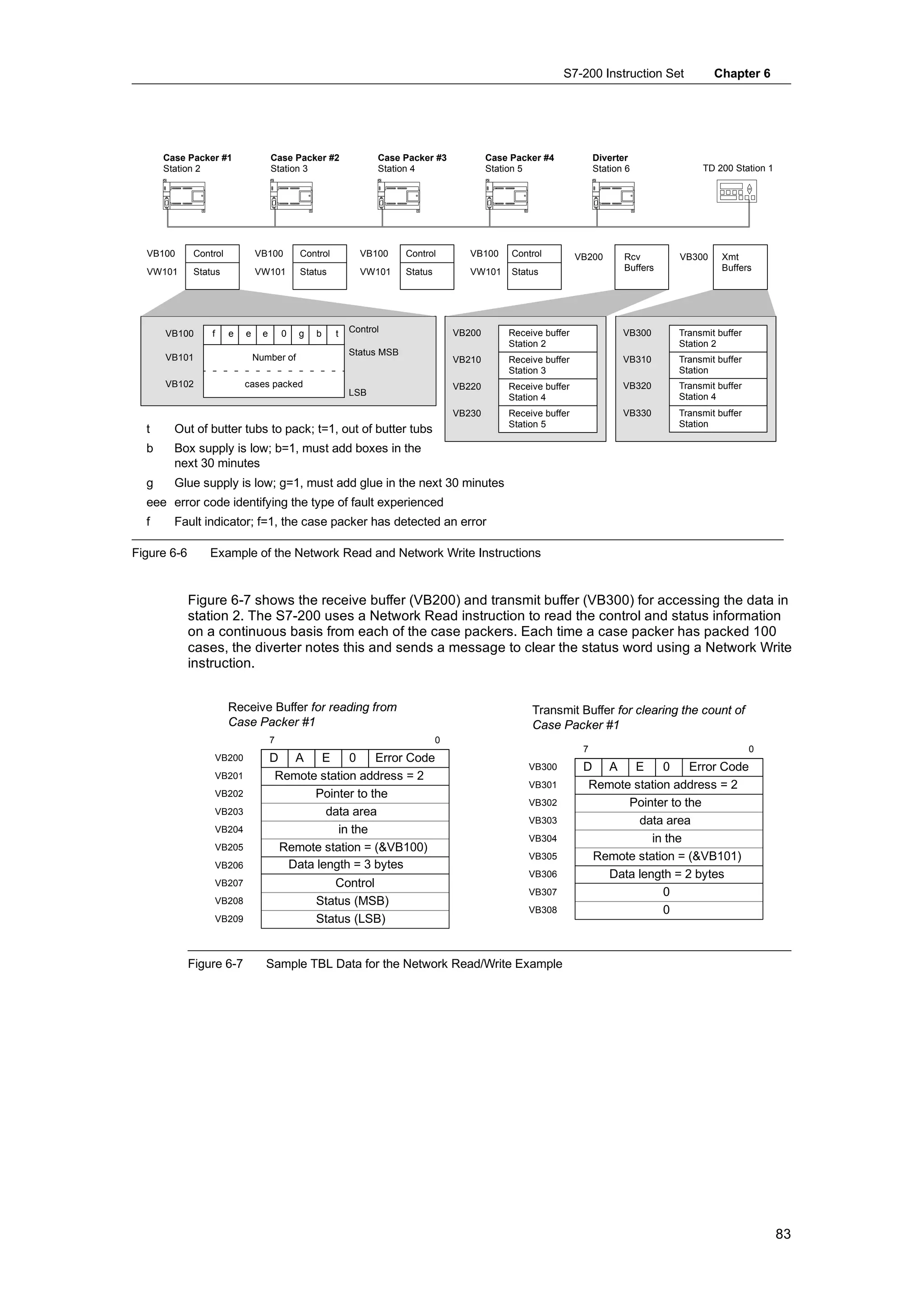
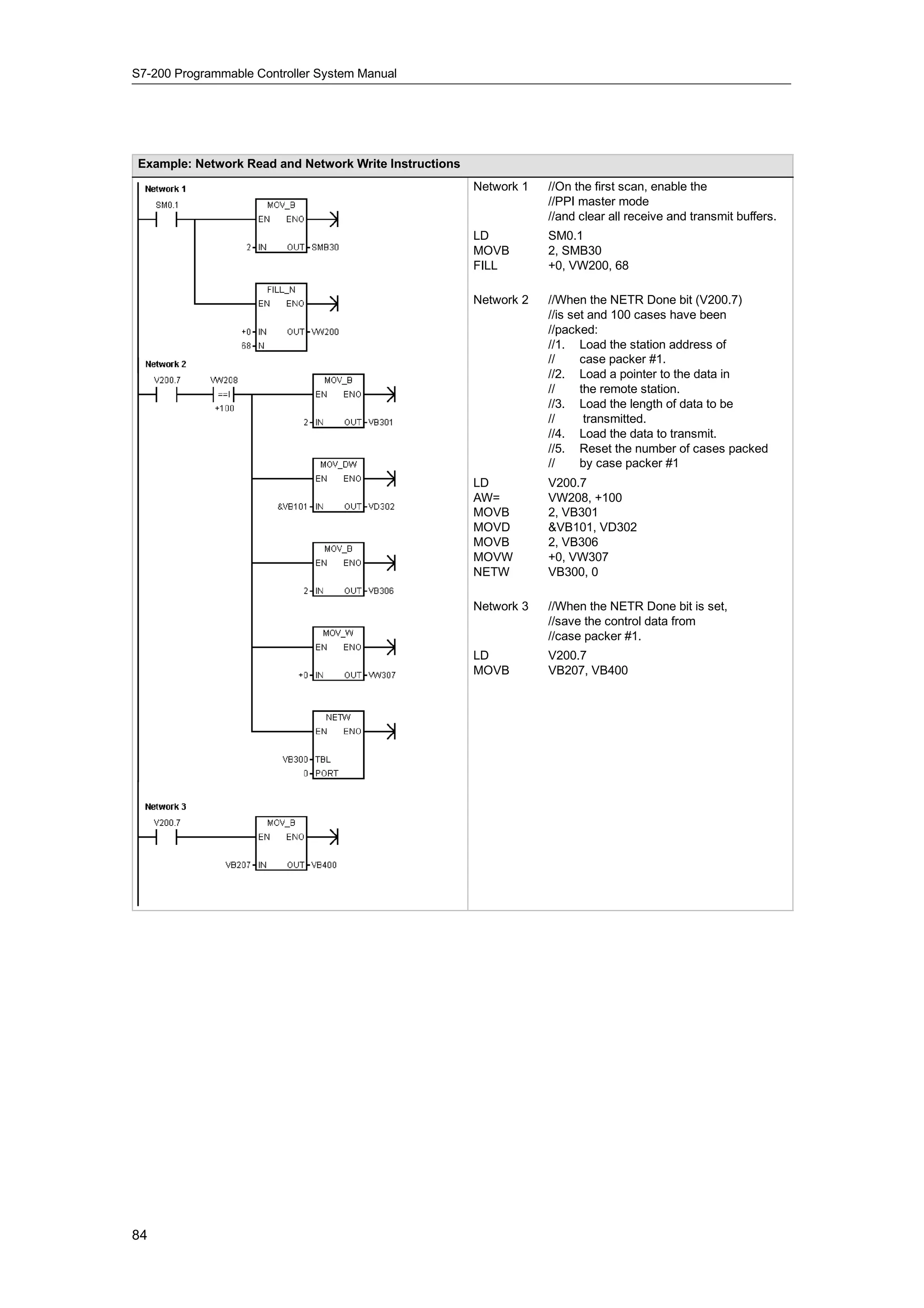
Format: C[counter number] C24
I2.1 MOV_W C3
Current Value Counter Bits
EN
C0 C0
C3 IN OUT VW200
C1 C1
C2 C2
15 (MSB) C3 0 (LSB) C3
Accesses the current value Accesses the counter bit
Figure 4-7 Accessing the Counter Bit or the Current Value of a Counter
29](https://image.slidesharecdn.com/s7200systemmanualen-us-121009044520-phpapp02/75/S72-00-system-manual_en-us-43-2048.jpg)
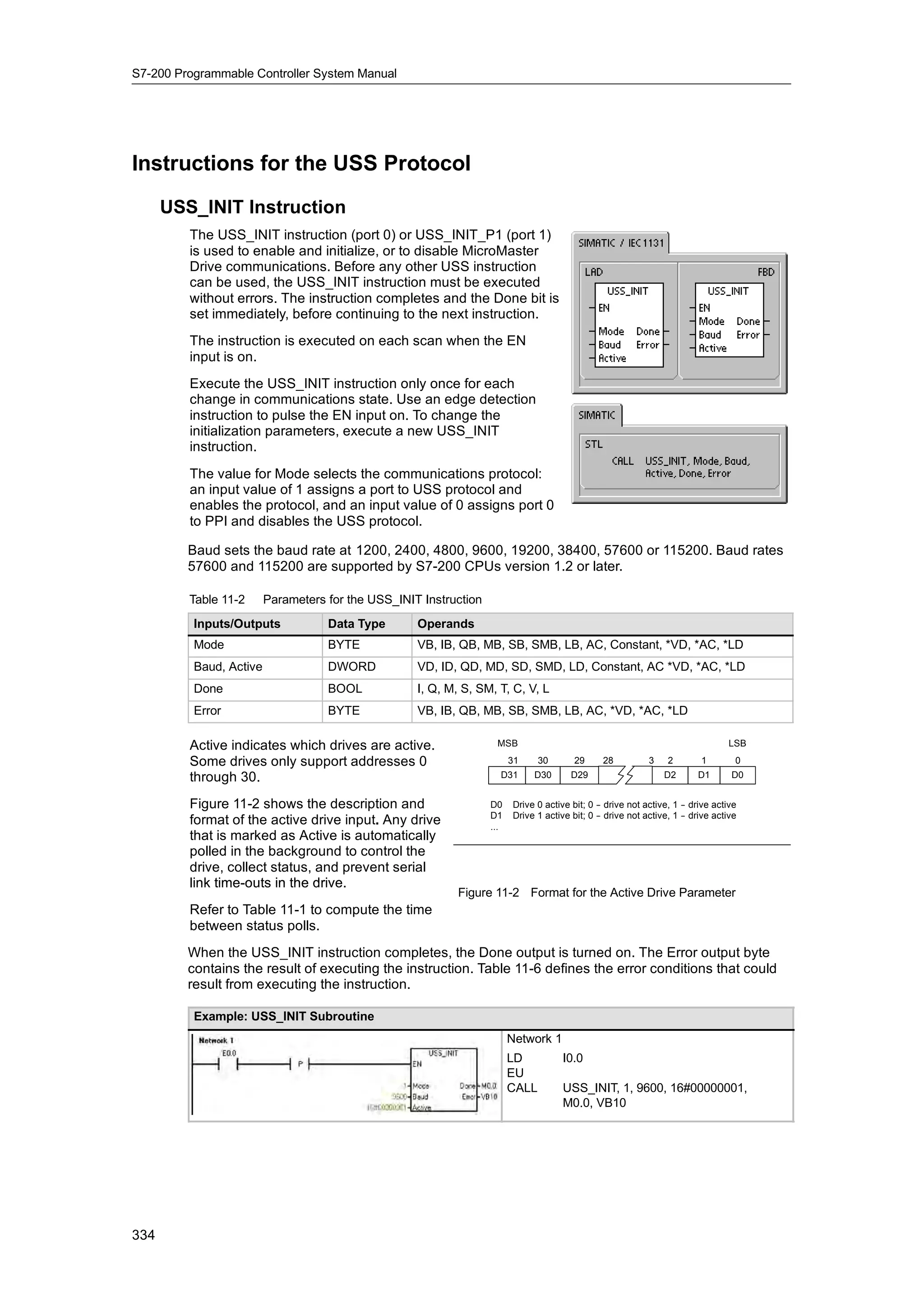
![S7-200 Programmable Controller System Manual
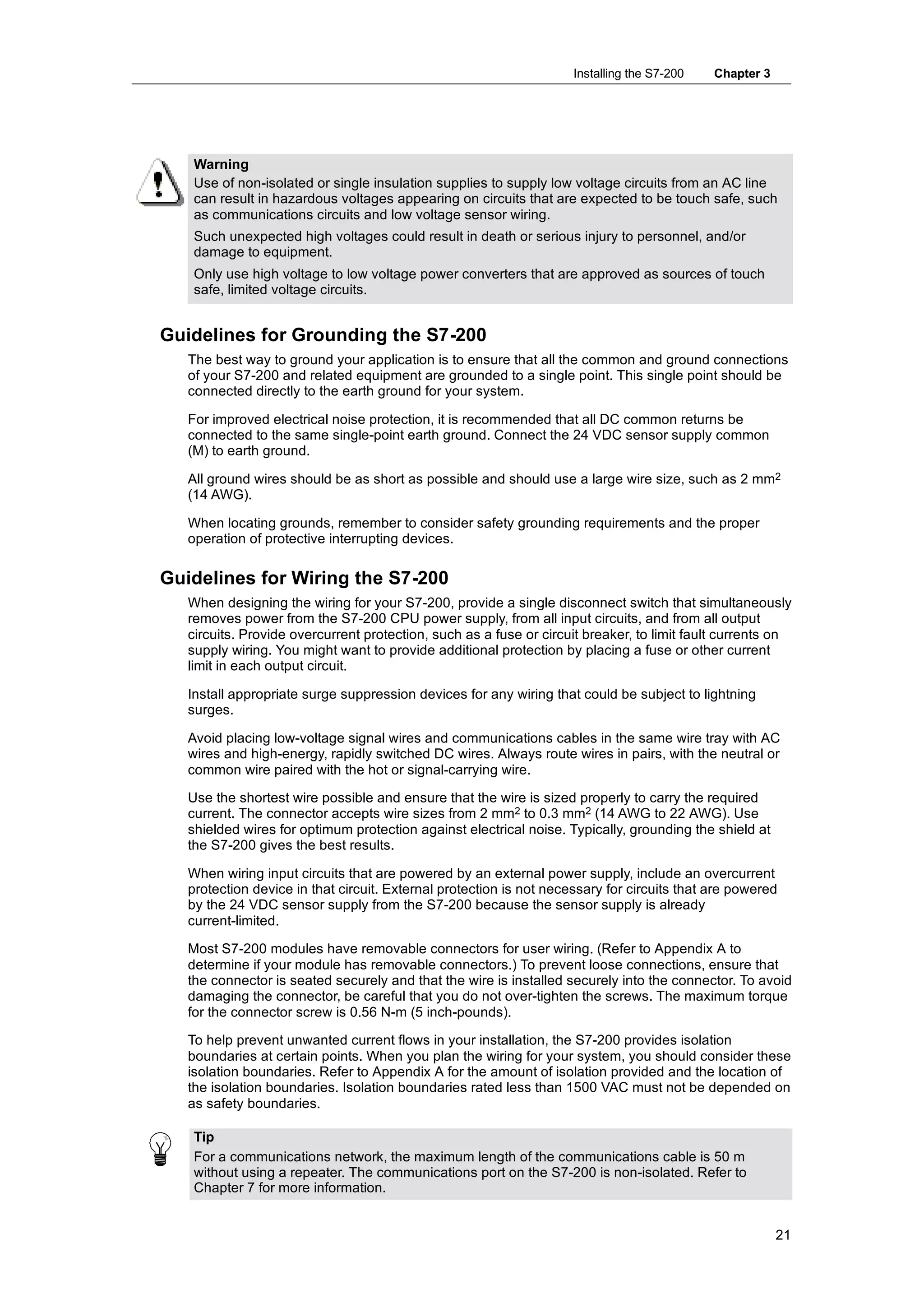
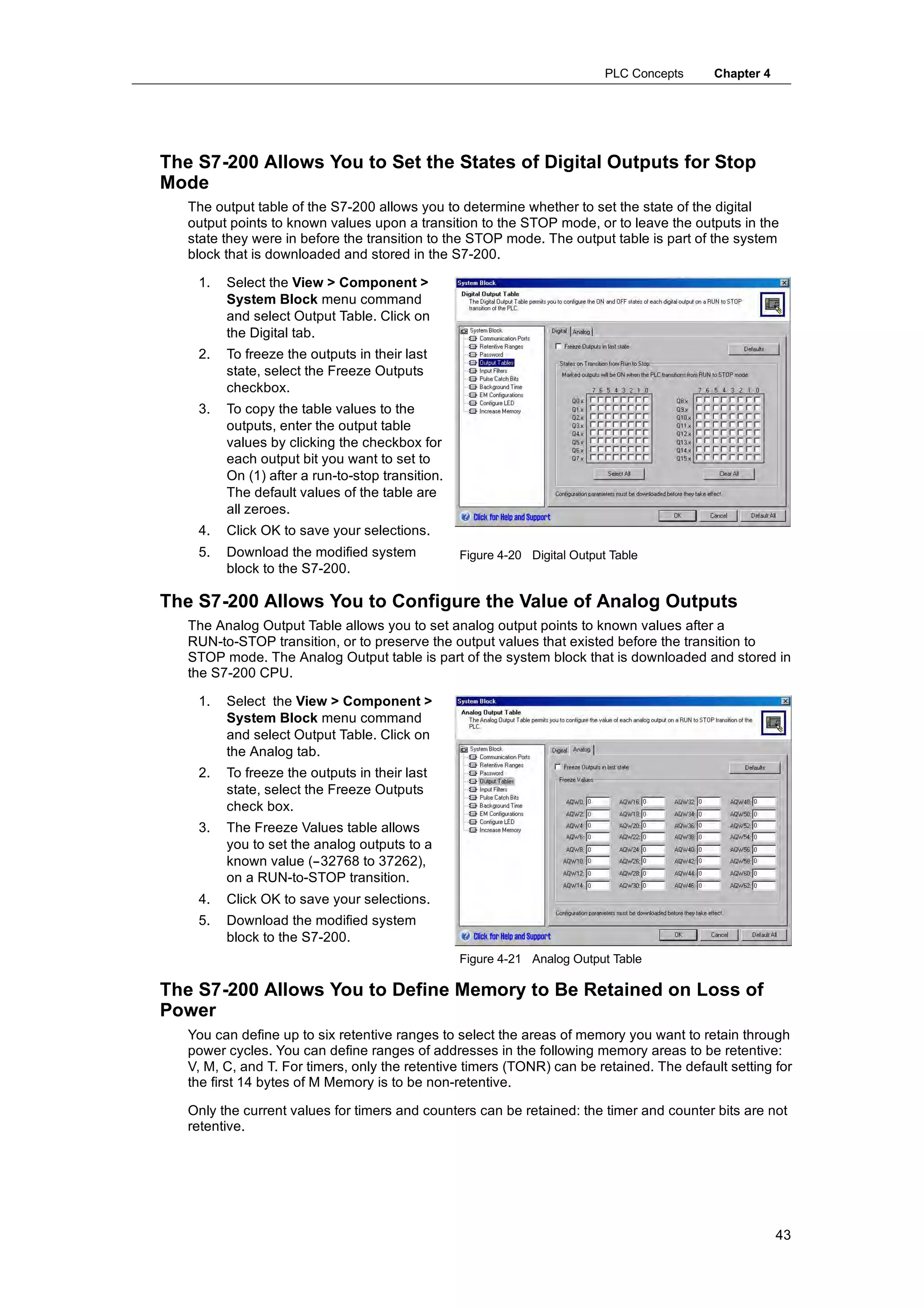
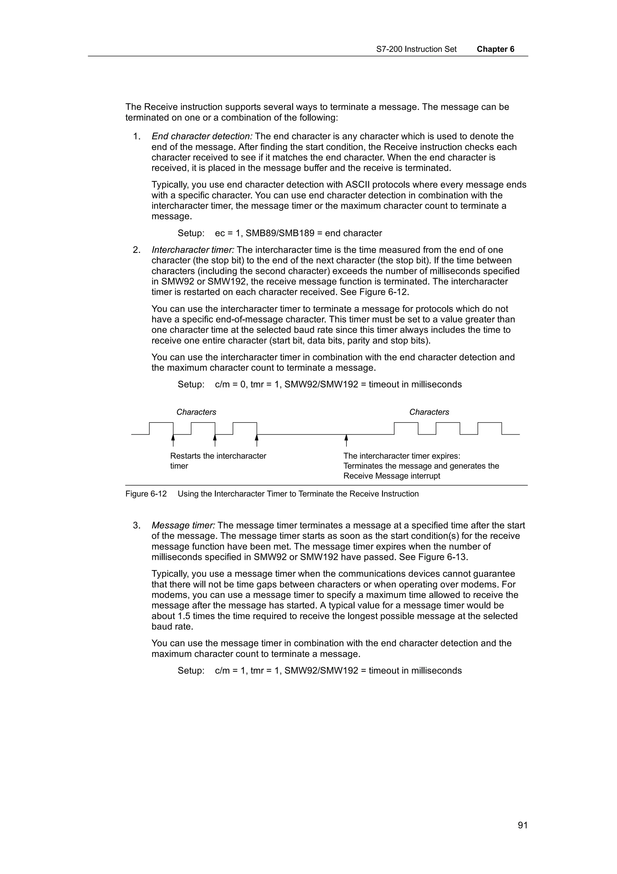
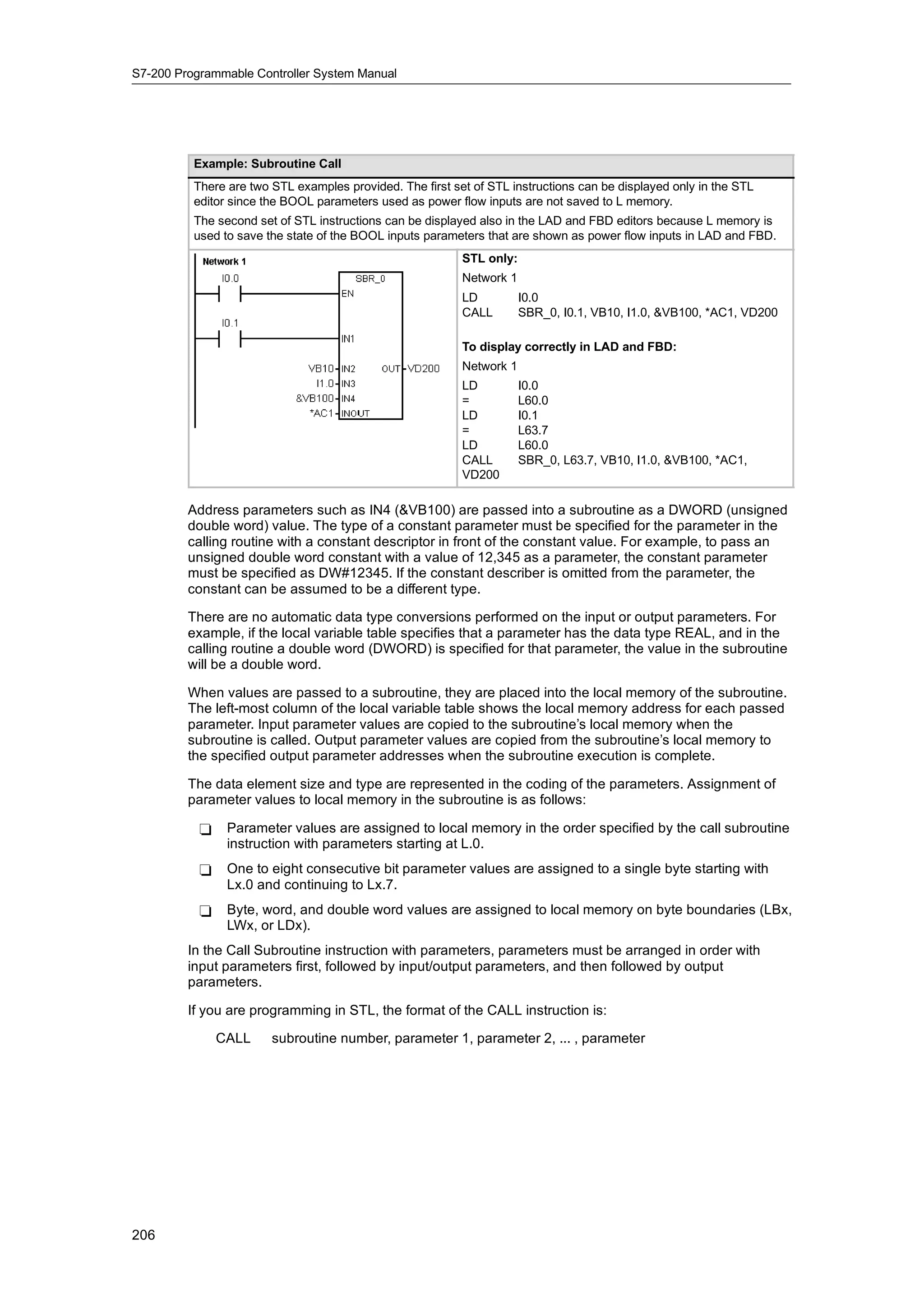
High-Speed Counters: HC
The high-speed counters count high-speed events independent of the CPU scan. High-speed
counters have a signed, 32-bit integer counting value (or current value). To access the count
value for the high-speed counter, you specify the address of the high-speed counter, using the
memory type (HC) and the counter number (such as HC0). The current value of the high-speed
counter is a read-only value and can be addressed only as a double word (32 bits).
Format: HC[high-speed counter number] HC1
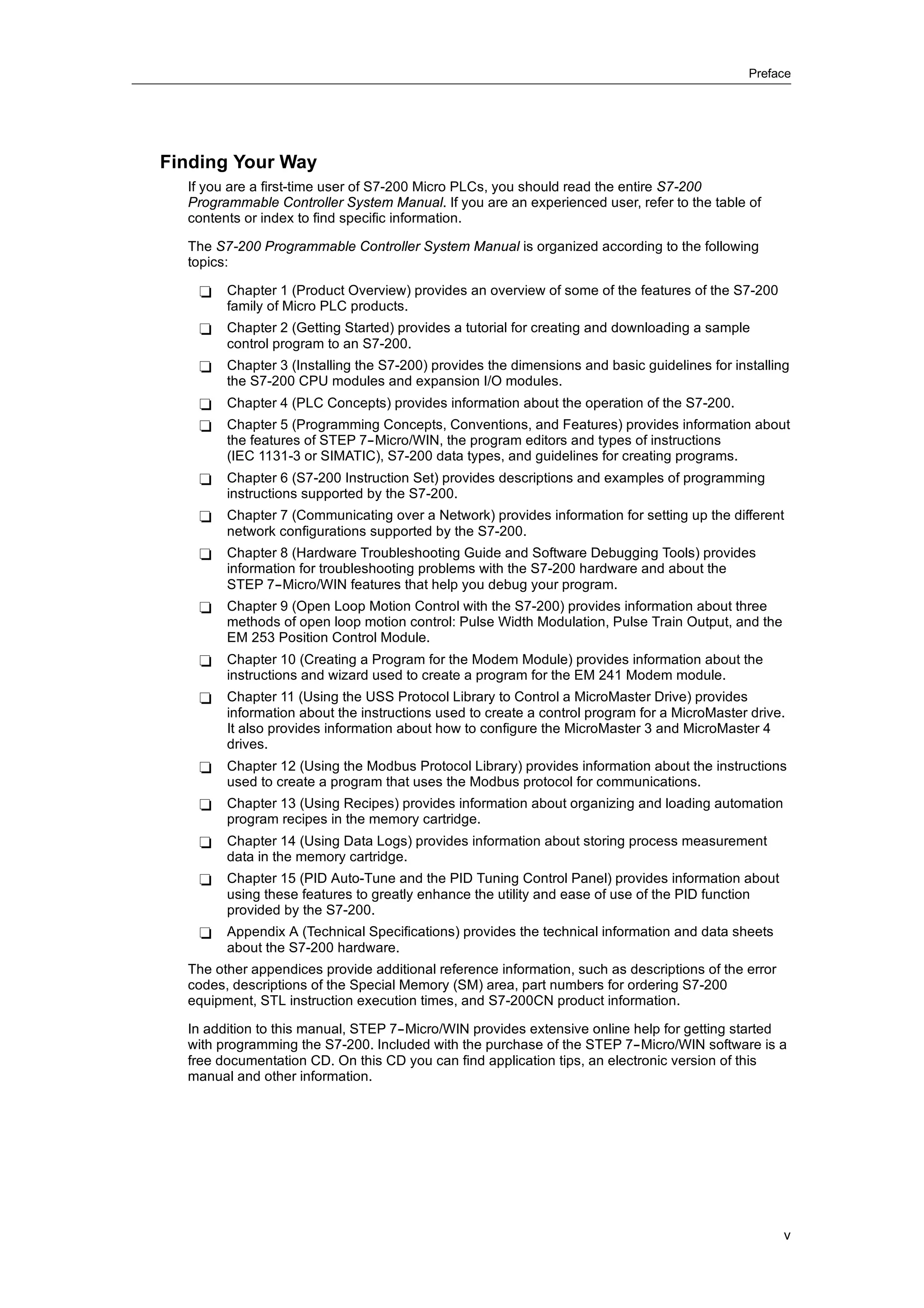
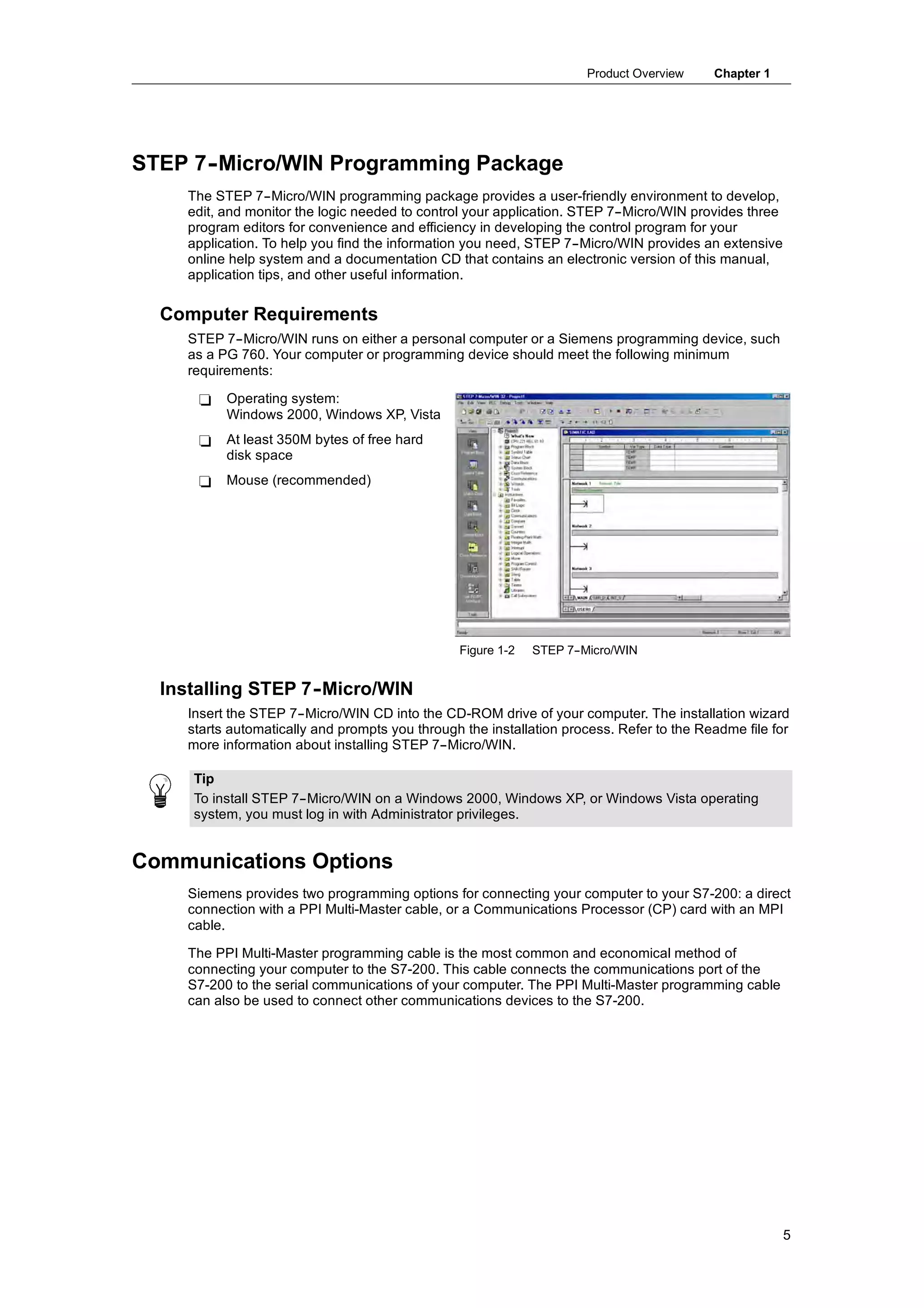
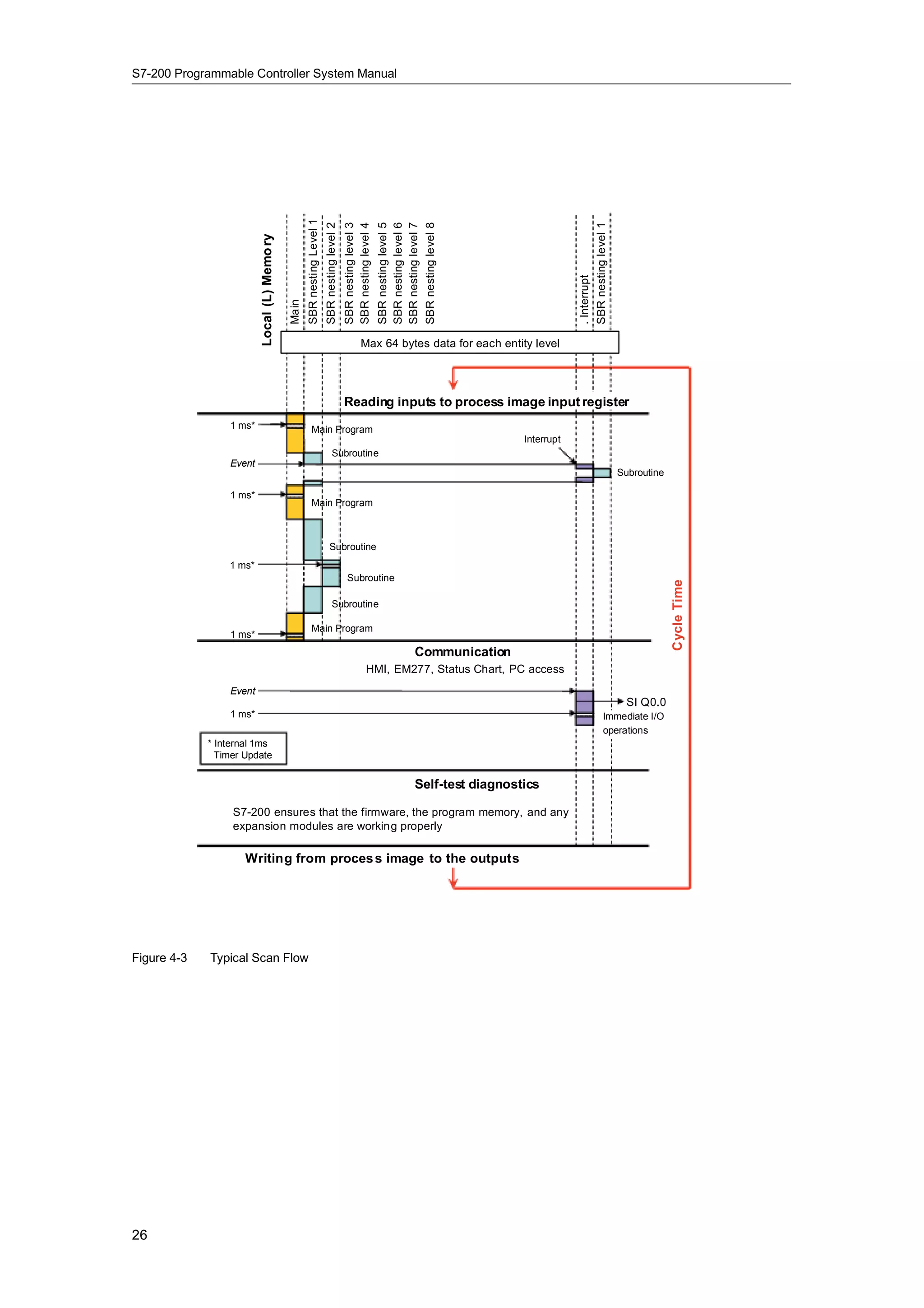
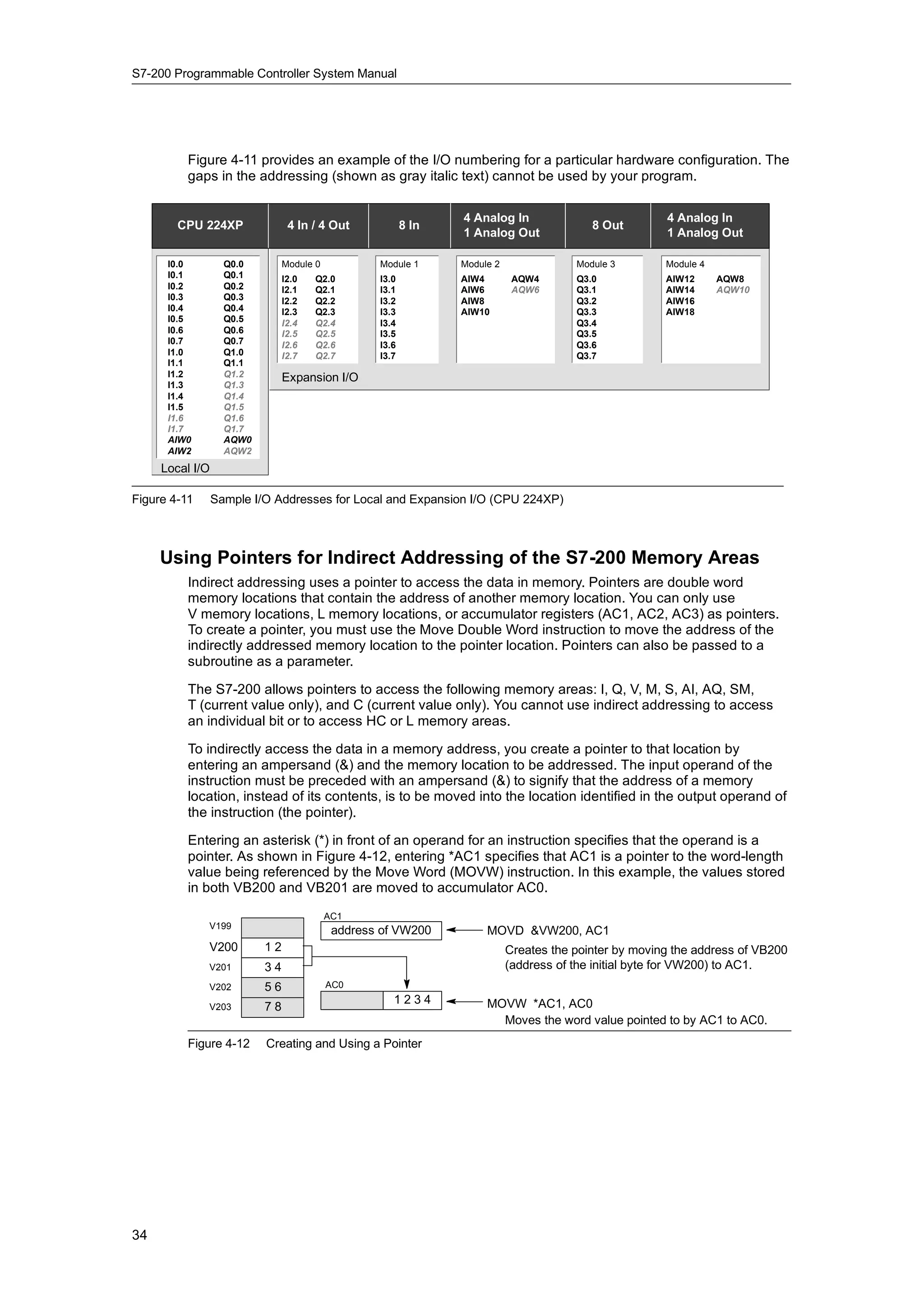
Accumulators: AC
The accumulators are read/write devices that can be used like memory. For example, you can use
accumulators to pass parameters to and from subroutines and to store intermediate values used
in a calculation. The S7-200 provides four 32-bit accumulators (AC0, AC1, AC2, and AC3). You
can access the data in the accumulators as bytes, words, or double words.
The size of the data being accessed is determined by the instruction that is used to access the
accumulator. As shown in Figure 4-8, you use the least significant 8 or 16 bits of the value that is
stored in the accumulator to access the accumulator as bytes or words. To access the
accumulator as a double word, you use all 32 bits.
For information about how to use the accumulators within interrupt subroutines, refer to the
Interrupt Instructions in Chapter 6.
Format: AC[accumulator number] AC0
AC2 (accessed as a byte) MSB LSB
7 0
AC1 (accessed as a word) MSB LSB
15 8 7 0
Most significant Least significant
Byte 1 Byte 0
AC3 (accessed as a double word)
MSB LSB
31 24 23 16 15 8 7 0
Most significant Least significant
Byte 3 Byte 2 Byte 1 Byte 0
Figure 4-8 Accessing the Accumulators
30](https://image.slidesharecdn.com/s7200systemmanualen-us-121009044520-phpapp02/75/S72-00-system-manual_en-us-44-2048.jpg)
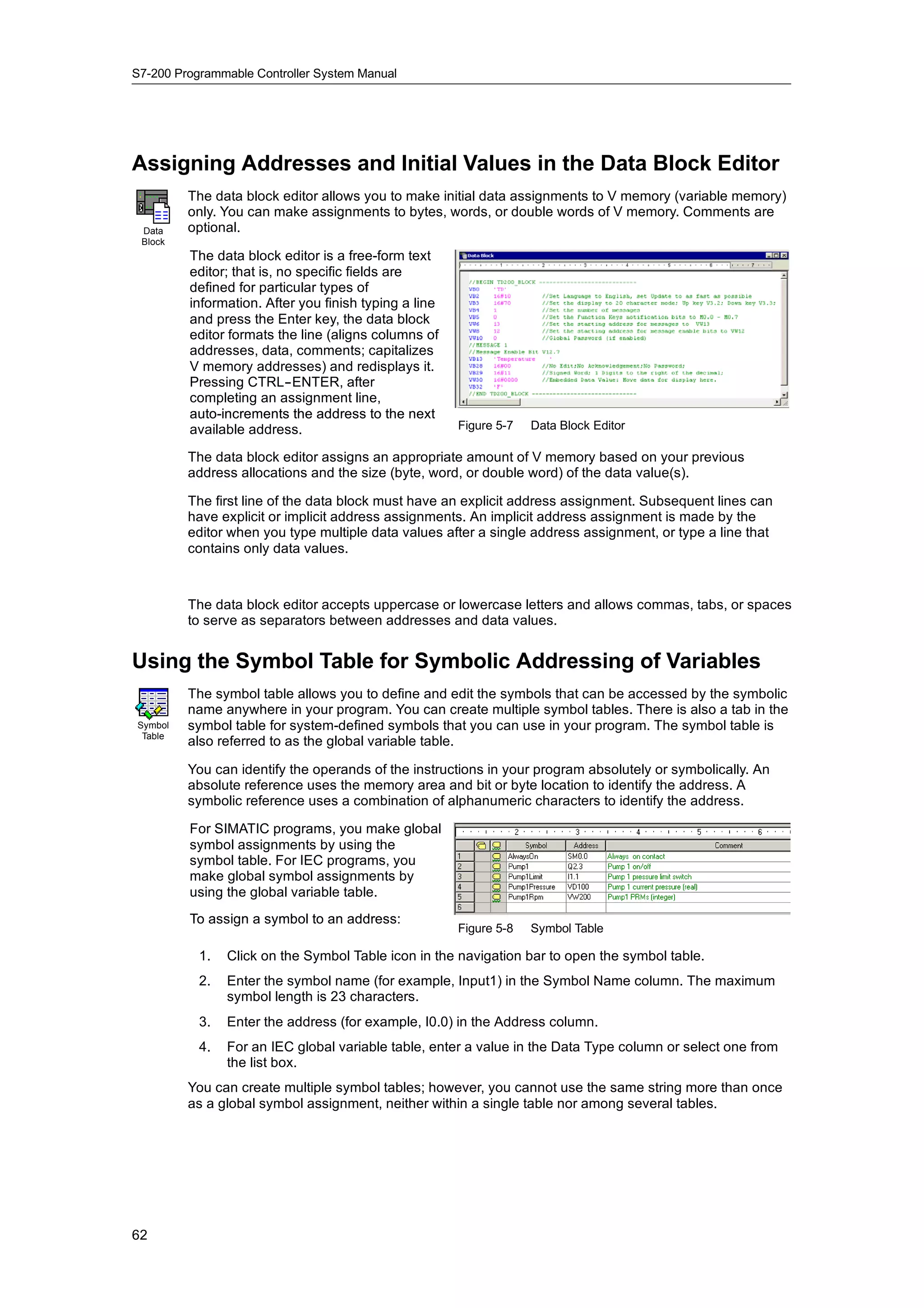
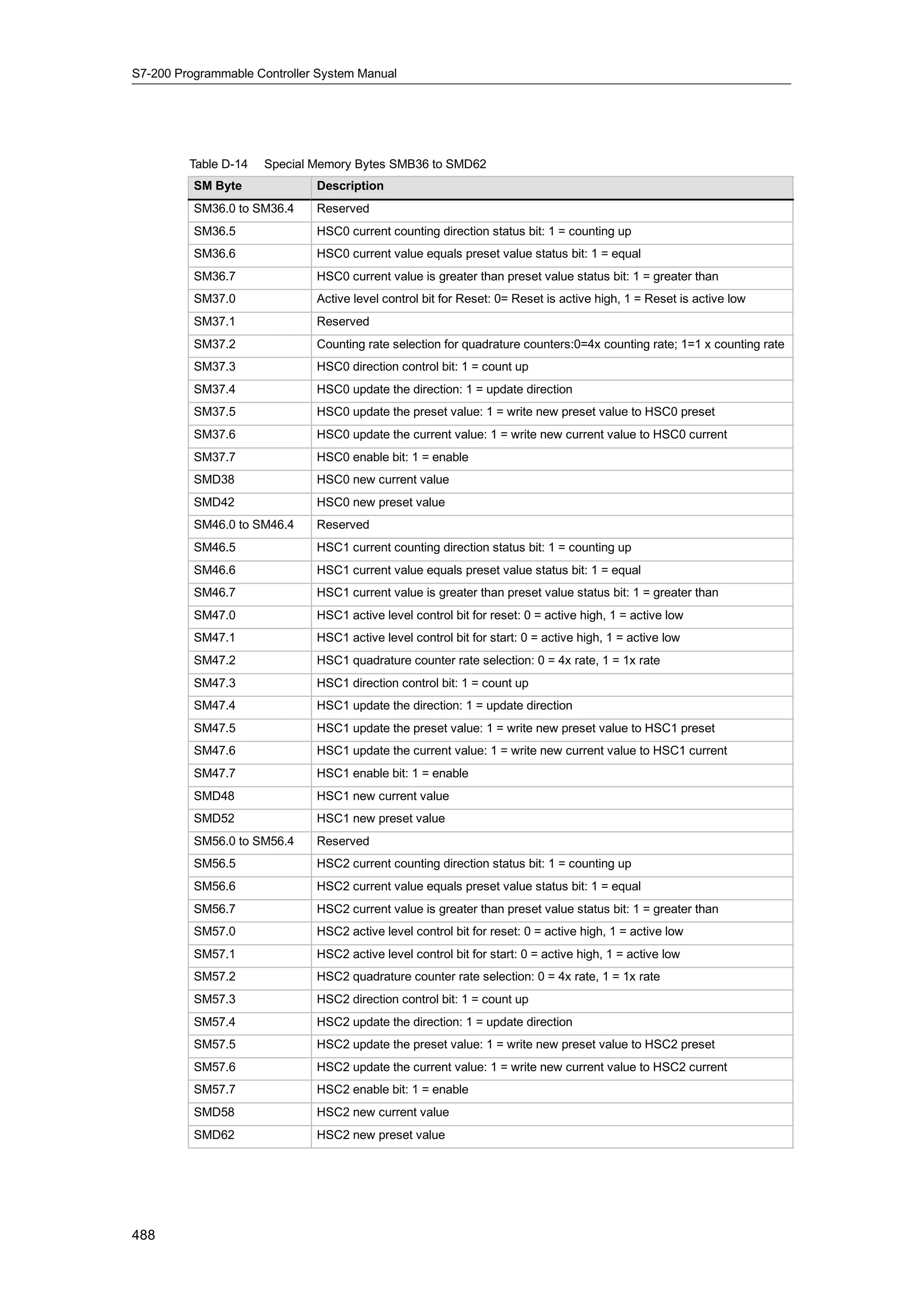
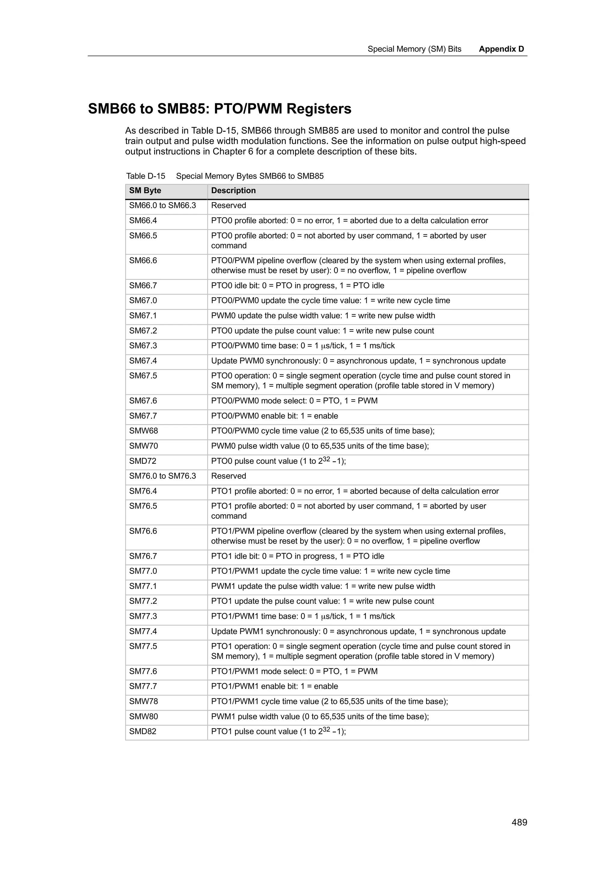
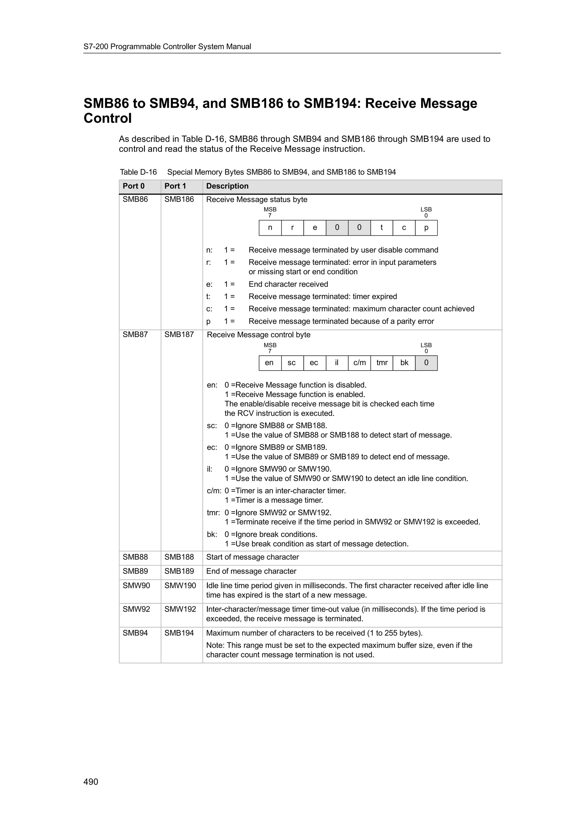
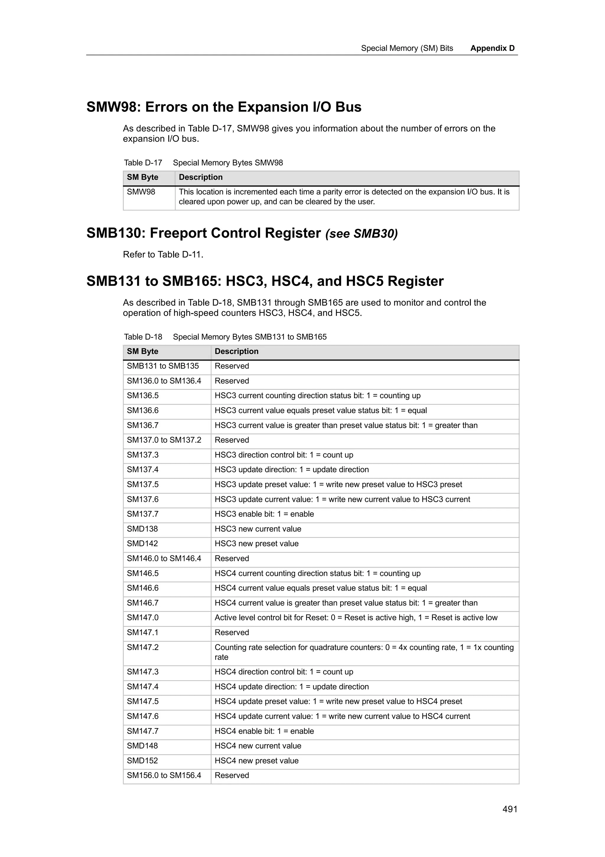
![PLC Concepts Chapter 4
Special Memory: SM
The SM bits provide a means for communicating information between the CPU and your program.
You can use these bits to select and control some of the special functions of the S7-200 CPU,
such as: a bit that turns on for the first scan cycle, a bit that toggles at a fixed rate, or a bit that
shows the status of math or operational instructions. (For more information about the SM bits, see
Appendix D.) You can access the SM bits as bits, bytes, words, or double words:
Bit: SM[byte address].[bit address] SM0.1
Byte, Word, or Double Word: SM[size][starting byte address] SMB86
Local Memory Area: L
The S7-200 provides 64 bytes of local memory of which 60 can be used as scratchpad memory or
for passing formal parameters to subroutines.
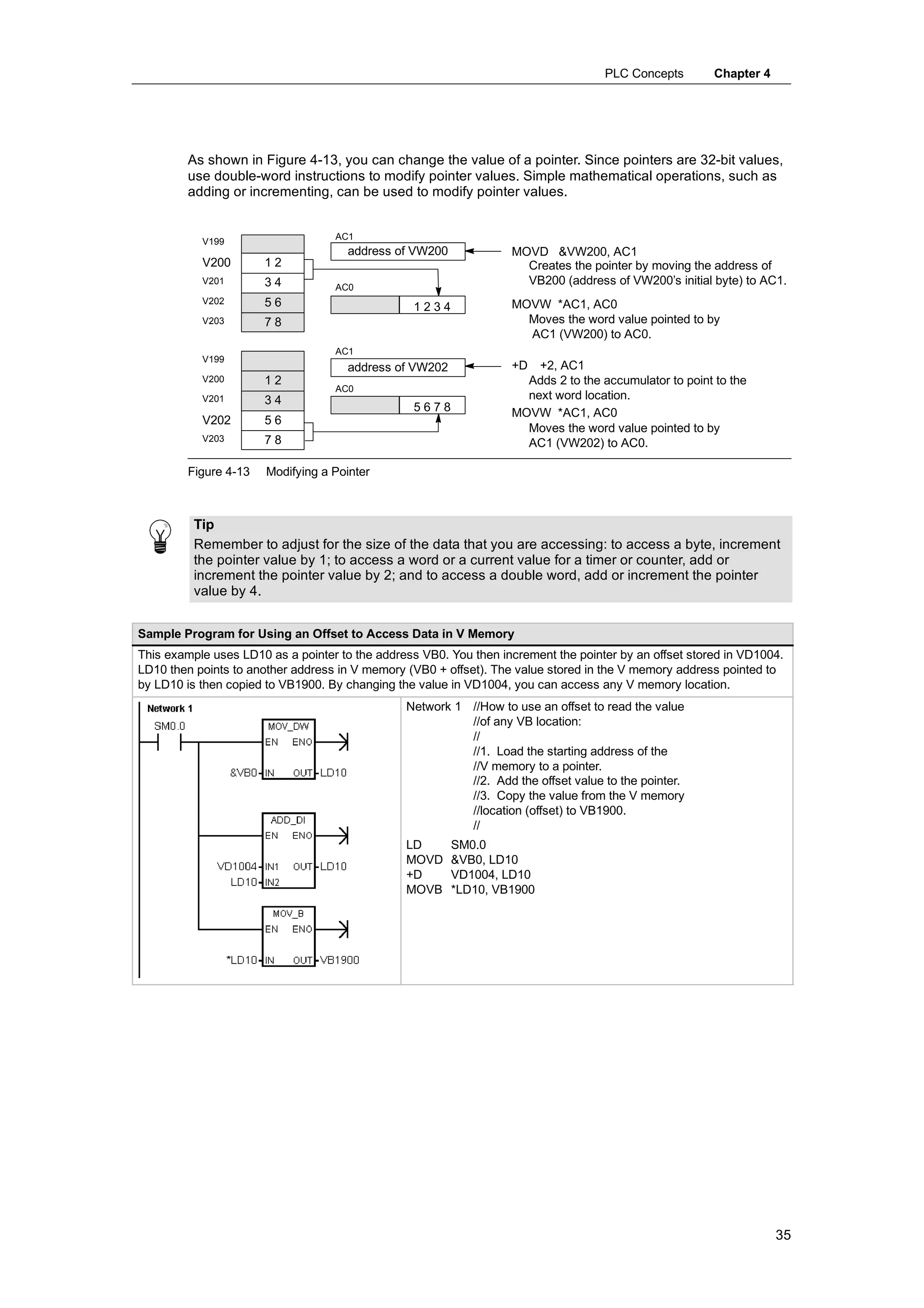
Tip
If you are programming in either LAD or FBD, STEP 7--Micro/WIN reserves the last four bytes of
local memory for its own use.
Local memory is similar to V memory with one major exception. V memory has a global scope
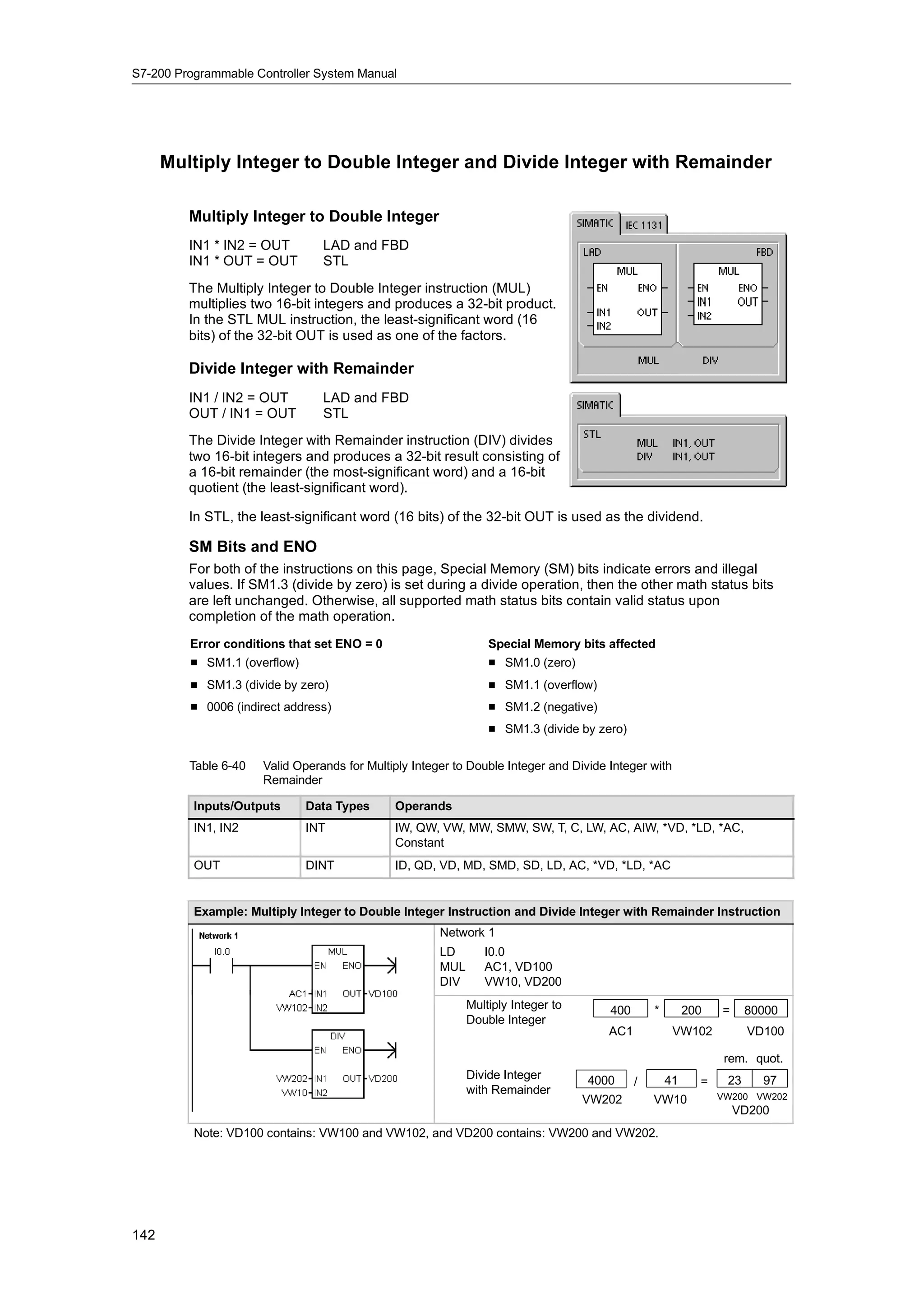
while L memory has a local scope. The term global scope means that the same memory location
can be accessed from any program entity (main program, subroutines, or interrupt routines). The
term local scope means that the memory allocation is associated with a particular program entity.
The S7-200 allocates 64 bytes of L memory for the main program, 64 bytes for each subroutine
nesting level, and 64 bytes for interrupt routines.
The allocation of L memory for the main program cannot be accessed from subroutines or from
interrupt routines. A subroutine cannot access the L memory allocation of the main program, an
interrupt routine, or another subroutine. Likewise, an interrupt routine cannot access the L memory
allocation of the main program or of a subroutine.
The allocation of L memory is made by the S7-200 on an as-needed basis. This means that while
the main portion of the program is being executed, the L memory allocations for subroutines and
interrupt routines do not exist. At the time that an interrupt occurs or a subroutine is called, local
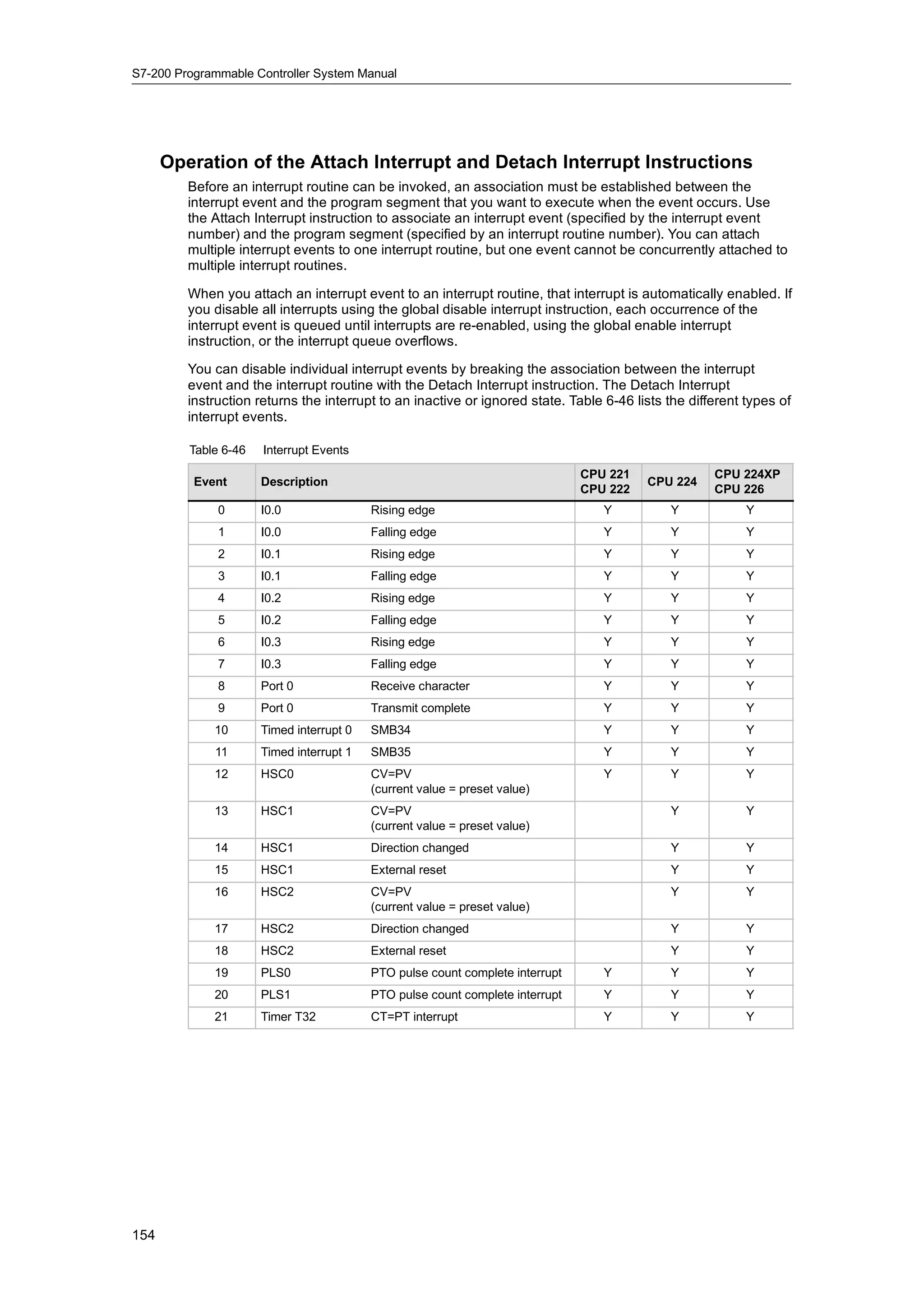
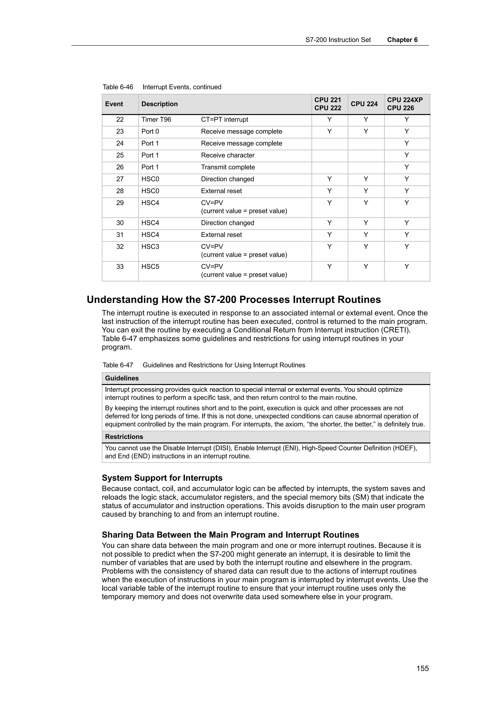
memory is allocated as required. The new allocation of L memory might reuse the same L
memory locations of a different subroutine or interrupt routine.
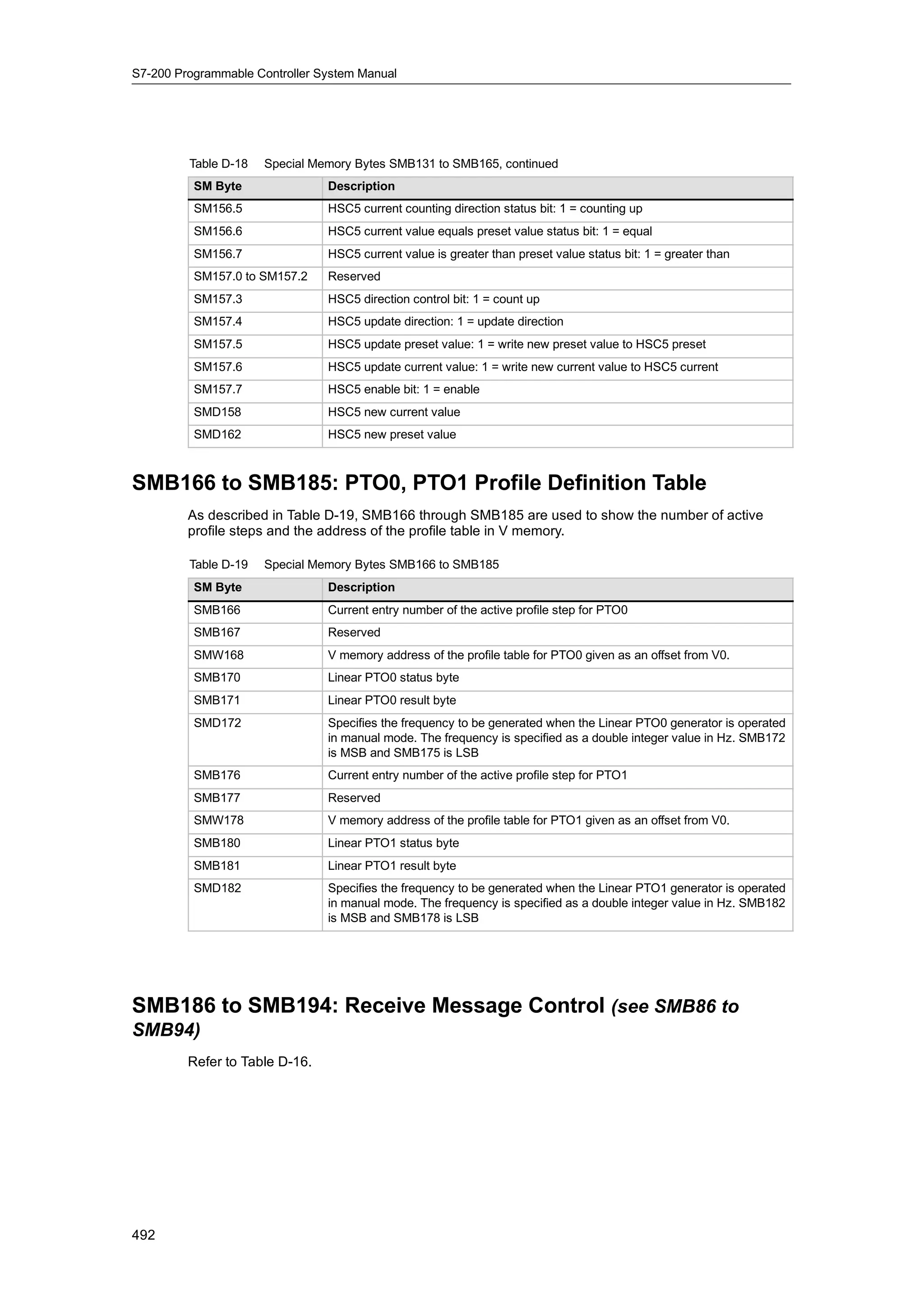
The L memory is not initialized by the S7-200 at the time of allocation and might contain any
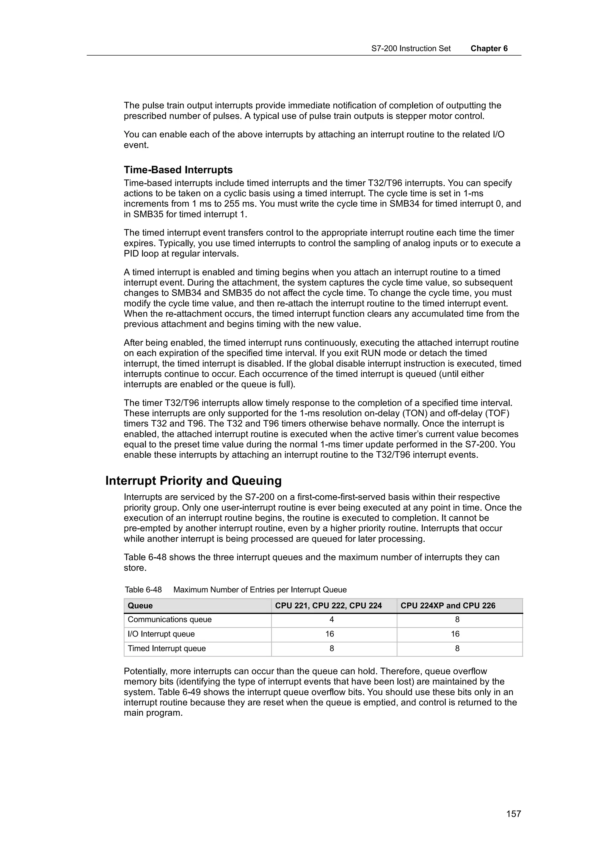
value. When you pass formal parameters in a subroutine call, the values of the parameters being
passed are placed by the S7-200 in the appropriate L memory locations of the called subroutine. L
memory locations, which do not receive a value as a result of the formal parameter passing step,
will not be initialized and might contain any value at the time of allocation.
Bit: L[byte address].[bit address] L0.0
Byte, Word, or Double Word: L[size] [starting byte address] LB33
Analog Inputs: AI
The S7-200 converts an analog value (such as temperature or voltage) into a word-length (16-bit)
digital value. You access these values by the area identifier (AI), size of the data (W), and the
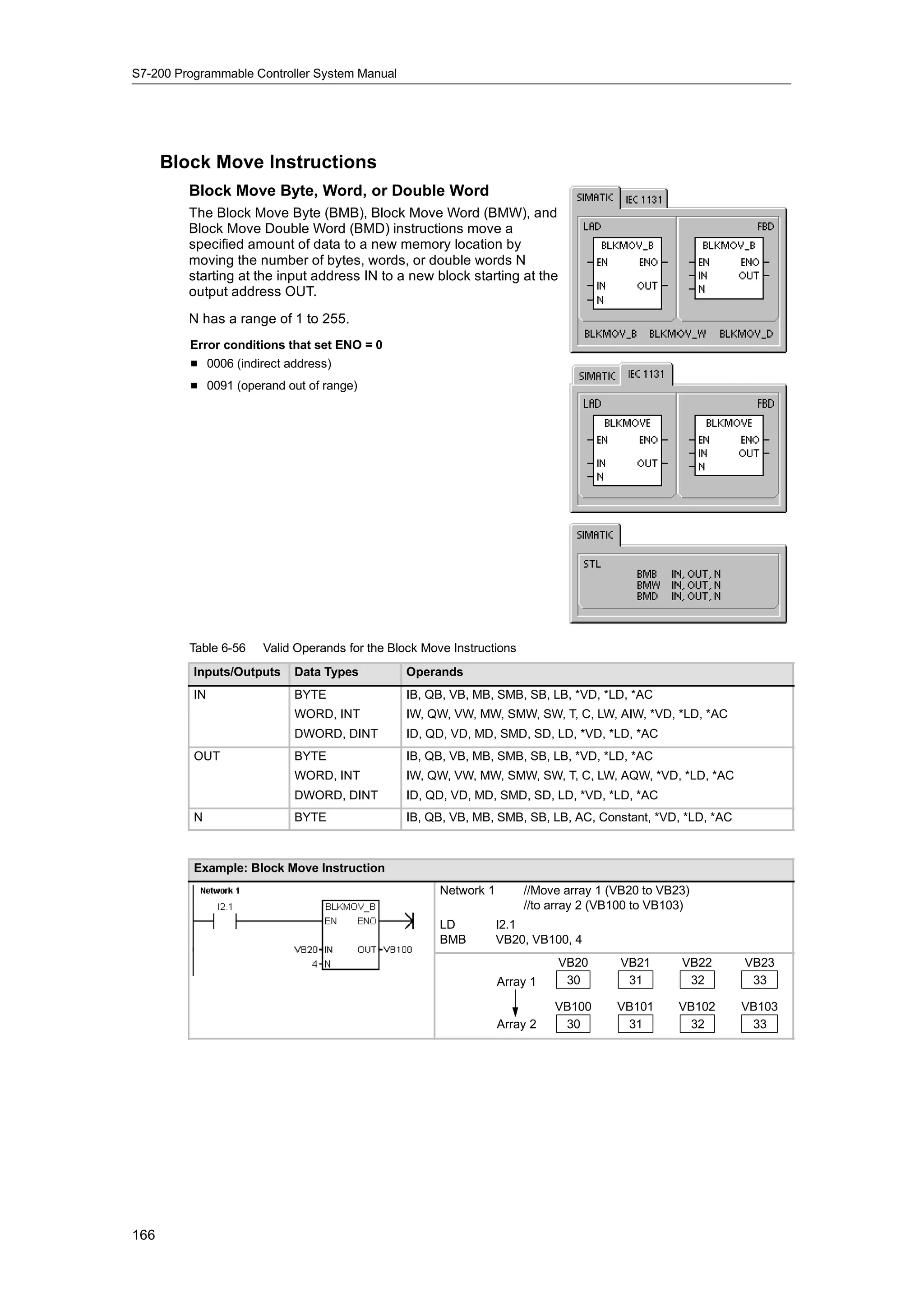
starting byte address. Since analog inputs are words and always start on even-number bytes
(such as 0, 2, or 4), you access them with even-number byte addresses (such as AIW0, AIW2, or
AIW4). Analog input values are read-only values.
Format: AIW[starting byte address] AIW4
31](https://image.slidesharecdn.com/s7200systemmanualen-us-121009044520-phpapp02/75/S72-00-system-manual_en-us-45-2048.jpg)
![S7-200 Programmable Controller System Manual
Analog Outputs: AQ
The S7-200 converts a word-length (16-bit) digital value into a current or voltage, proportional to
the digital value (such as for a current or voltage). You write these values by the area identifier
(AQ), size of the data (W), and the starting byte address. Since analog outputs are words and
always start on even-number bytes (such as 0, 2, or 4), you write them with even-number byte
addresses (such as AQW0, AQW2, or AQW4). Analog output values are write-only values.
Format: AQW[starting byte address] AQW4
Sequence Control Relay (SCR) Memory Area: S
SCRs or S bits are used to organize machine operations or steps into equivalent program
segments. SCRs allow logical segmentation of the control program. You can access the S bits as
bits, bytes, words, or double words.
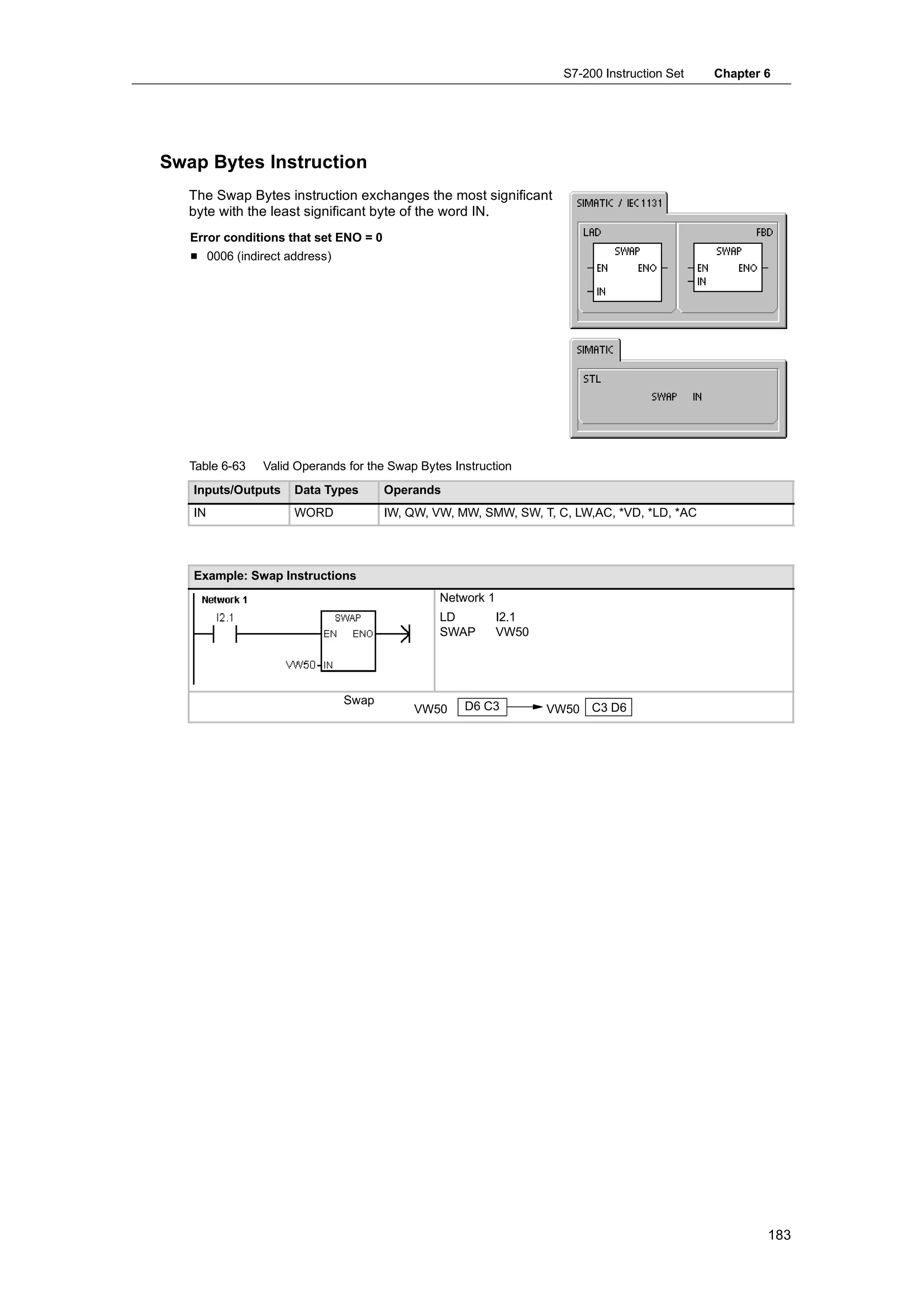
Bit: S[byte address].[bit address] S3.1
Byte, Word, or Double Word: S[size][starting byte address] SB4
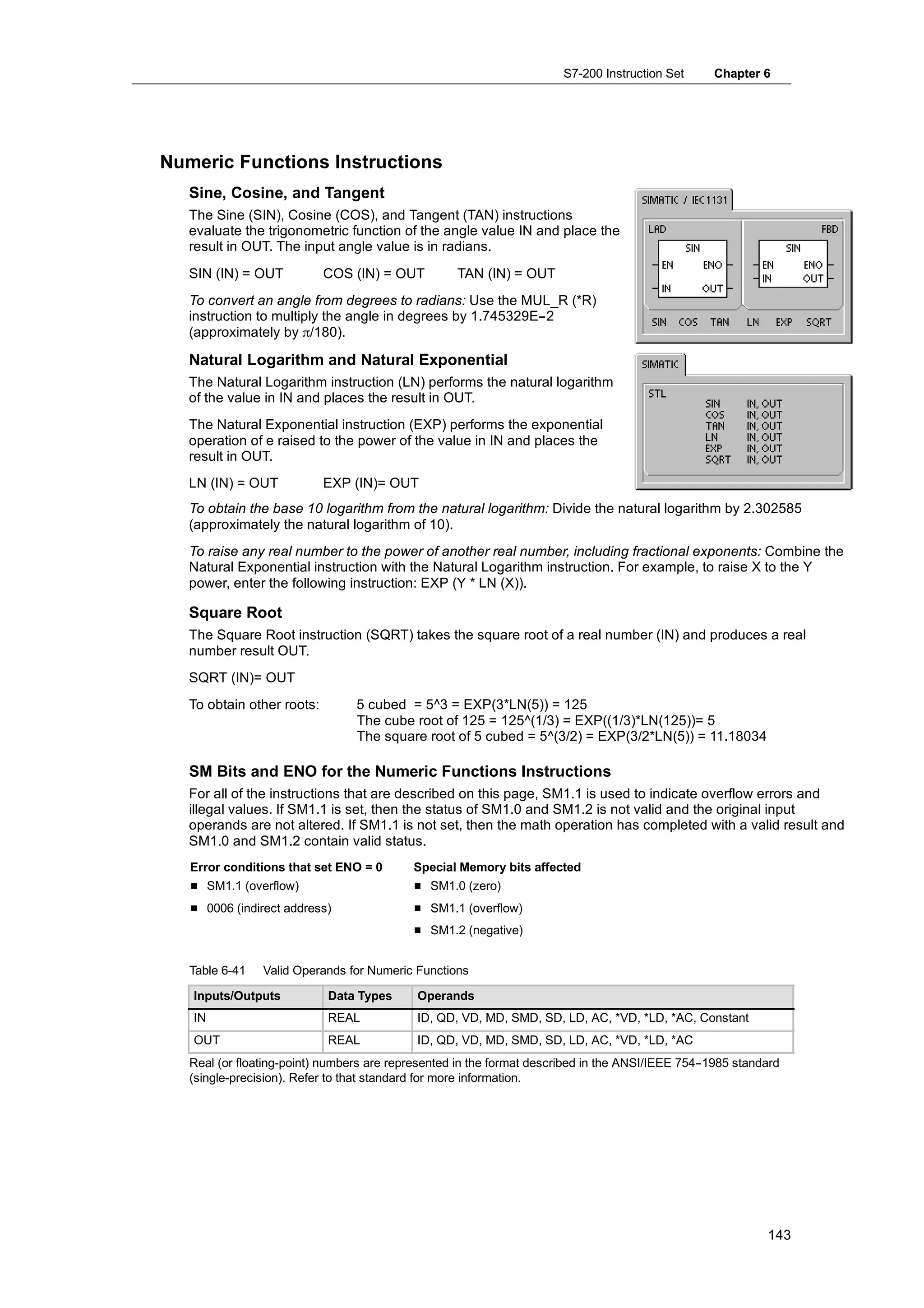
Format for Real Numbers
Real (or floating-point) numbers are represented as 32-bit, single-precision numbers, whose
format is described in the ANSI/IEEE 754--1985 standard. See Figure 4-9. Real numbers are
accessed in double-word lengths.
For the S7-200, floating point numbers are MSB LSB
31 30 23 22 0
accurate up to 6 decimal places. Therefore,
S Exponent Mantissa
you can specify a maximum of 6 decimal
places when entering a floating-point
p g gp Sign
constant.
t t Figure 4-9 Format of a Real Number
Accuracy when Calculating Real Numbers
Calculations that involve a long series of values including very large and very small numbers can
produce inaccurate results. This can occur if the numbers differ by 10 to the power of x,
where x > 6.
For example: 100 000 000 + 1 = 100 000 000
Format for Strings
A string is a sequence of characters, with each character being stored as a byte. The first byte of
the string defines the length of the string, which is the number of characters. Figure 4-10 shows
the format for a string. A string can have a length of 0 to 254 characters, plus the length byte, so
the maximum length for a string is 255 bytes. A string constant is limited to 126 bytes.
Length Character 1 Character 2 Character 3 Character 4 ... Character 254
Byte 0 Byte 1 Byte 2 Byte 3 Byte 4 Byte 254
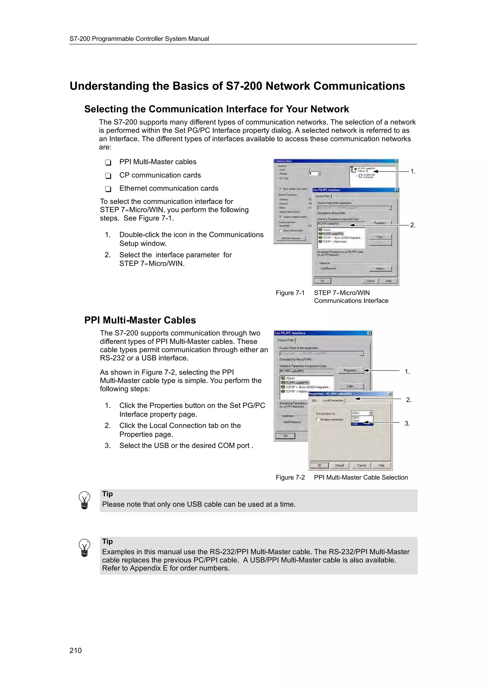
Figure 4-10 Format for Strings
32](https://image.slidesharecdn.com/s7200systemmanualen-us-121009044520-phpapp02/75/S72-00-system-manual_en-us-46-2048.jpg)
![PLC Concepts Chapter 4
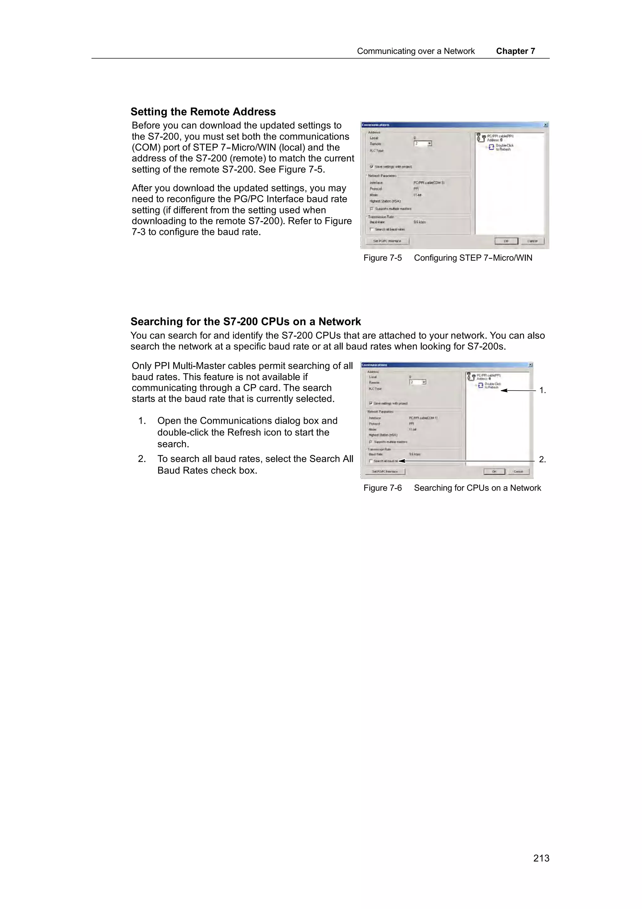
Specifying a Constant Value for S7-200 Instructions
You can use a constant value in many of the S7-200 instructions. Constants can be bytes, words,
or double words. The S7-200 stores all constants as binary numbers, which can then be
represented in decimal, hexadecimal, ASCII, or real number (floating point) formats. See
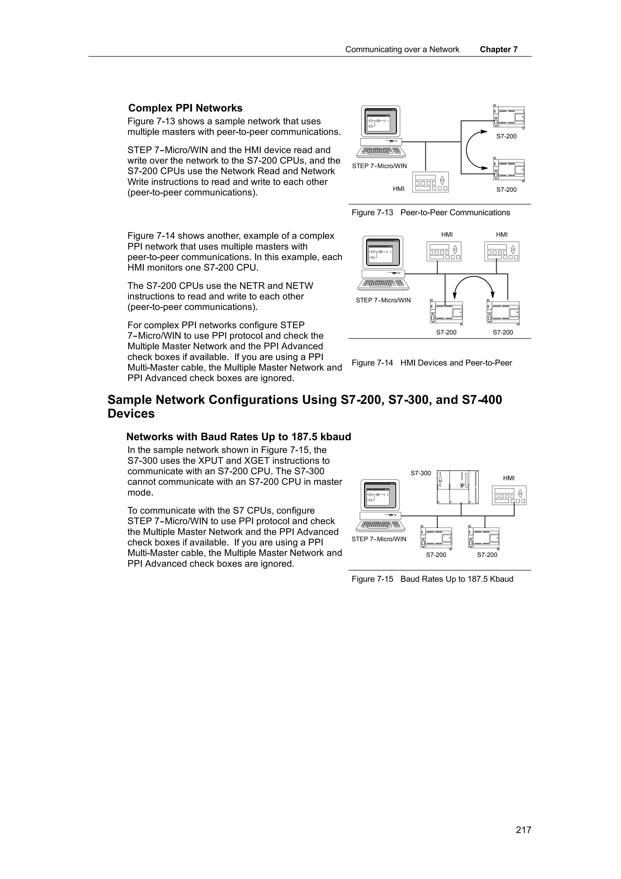
Table 4-2.
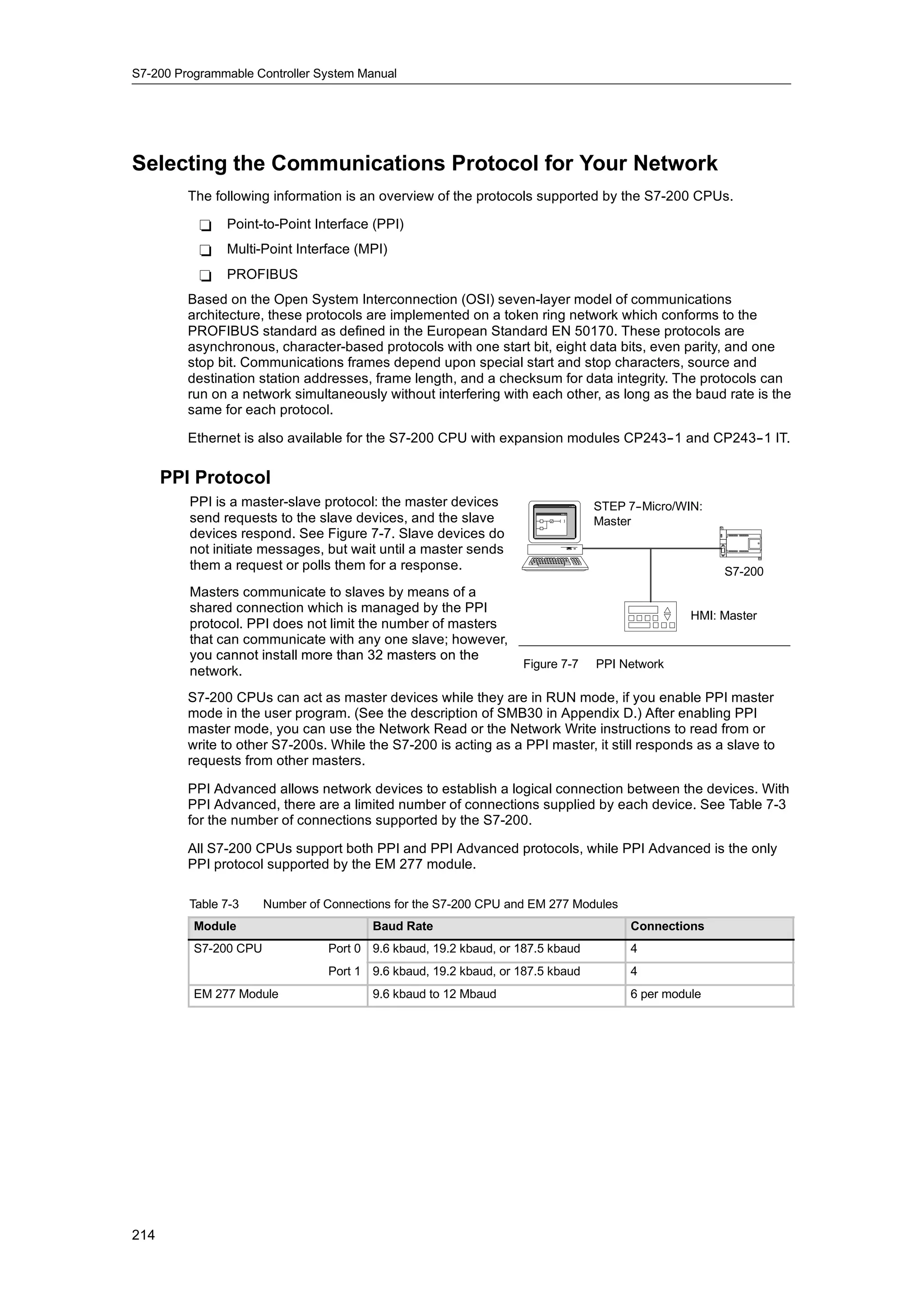
Table 4-2 Representation of Constant Values
Representation Format Sample
Decimal [decimal value] 20047
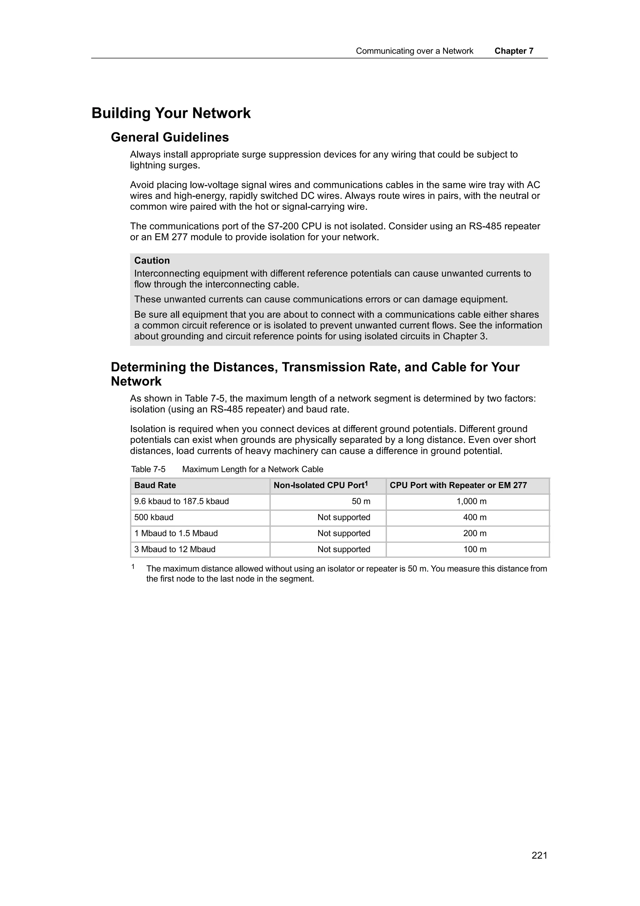
Hexadecimal 16#[hexadecimal value] 16#4E4F
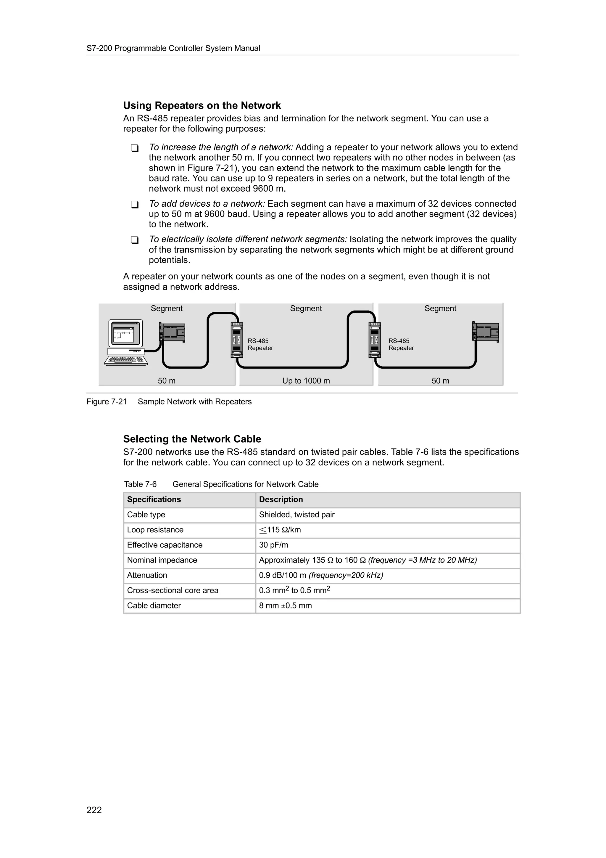
Binary 2#[binary number] 2#1010_0101_1010_0101
ASCII ’[ASCII text]’ ’ABCD’
Real ANSI/IEEE 754-
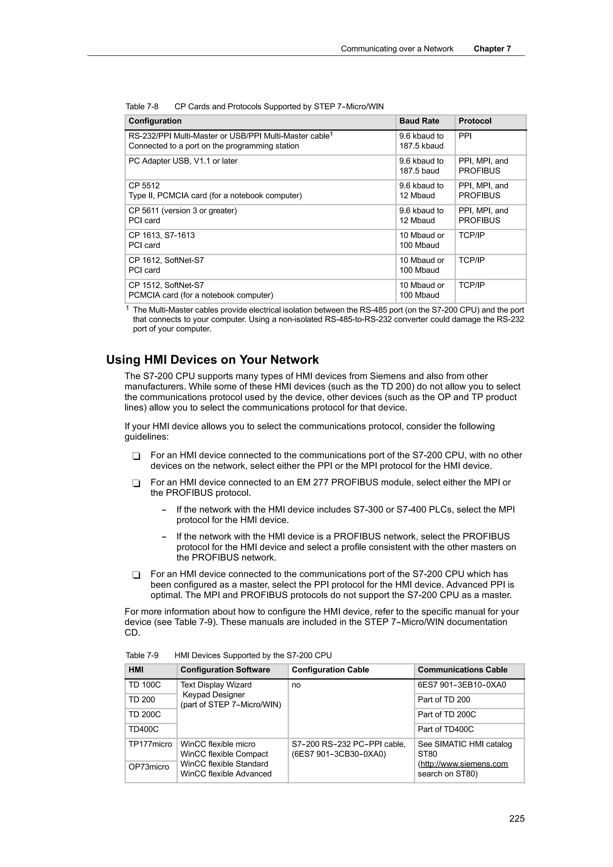
-1985 +1.175495E-
-38 (positive) -
-1.175495E-
-38 (negative)
String “[stringtext]” “ABCDE”
Tip
The S7-200 CPU does not support “data typing” or data checking (such as specifying that the
constant is stored as an integer, a signed integer, or a double integer). For example, an Add
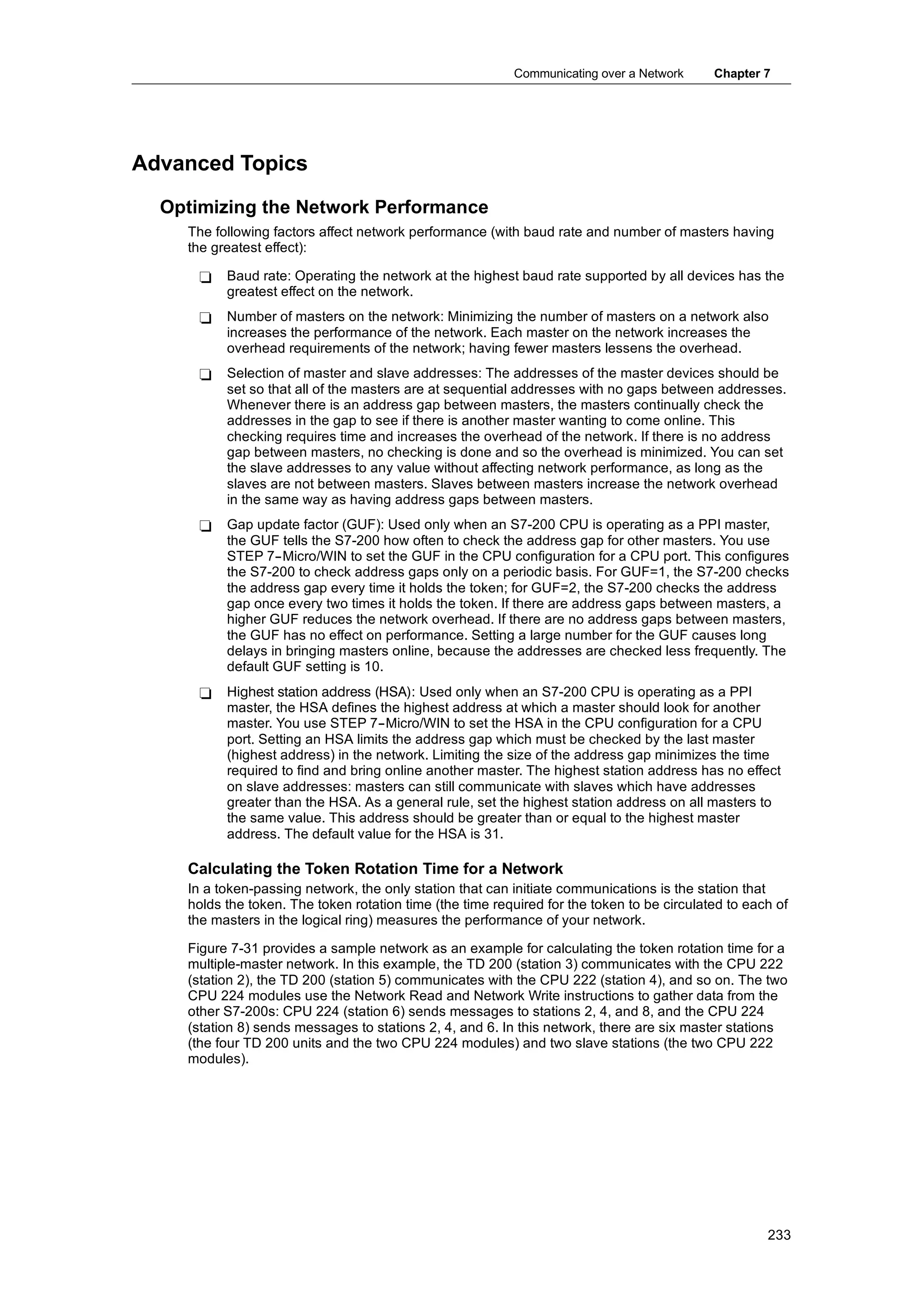
instruction can use the value in VW100 as a signed integer value, while an Exclusive Or
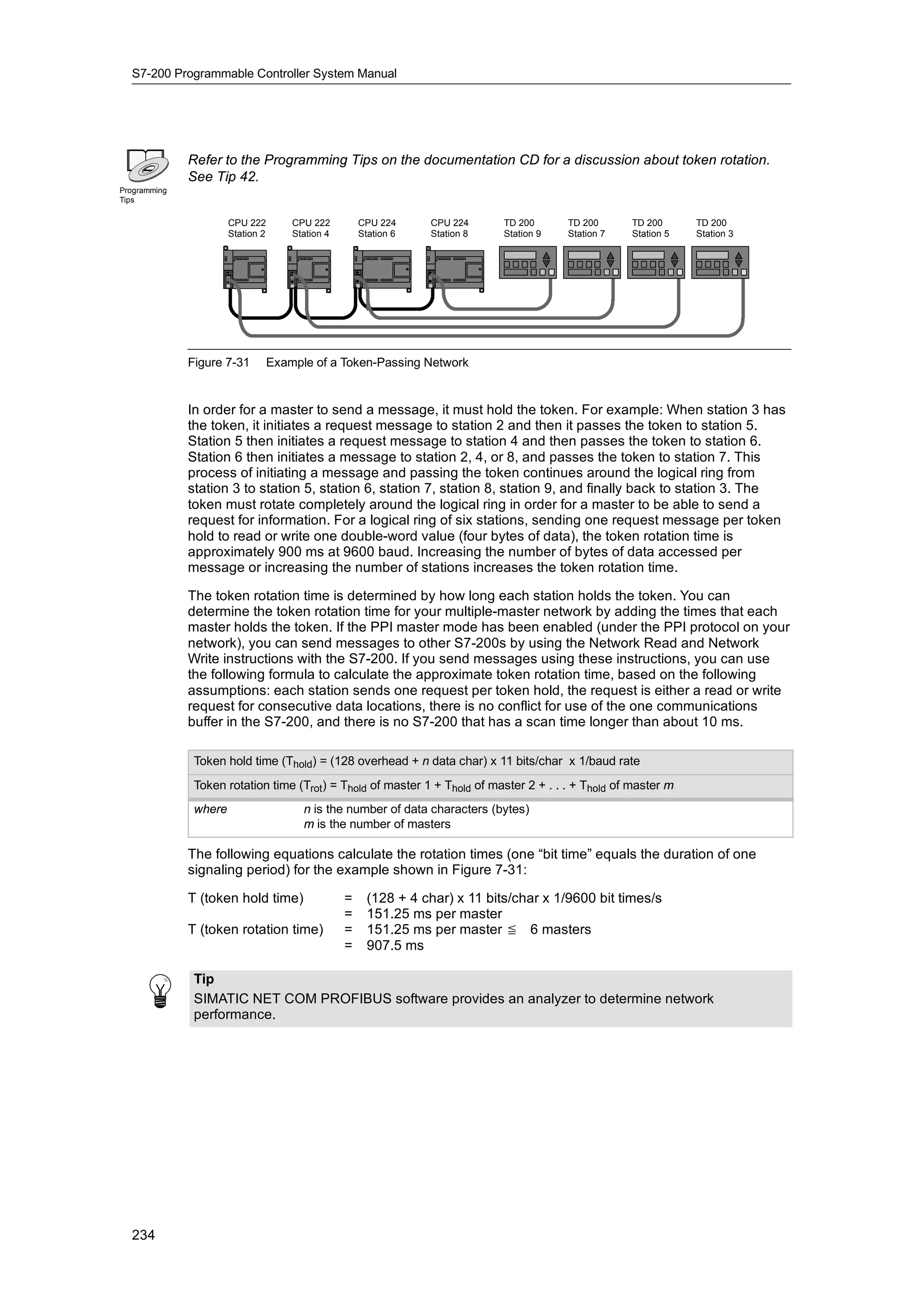
instruction can use the same value in VW100 as an unsigned binary value.
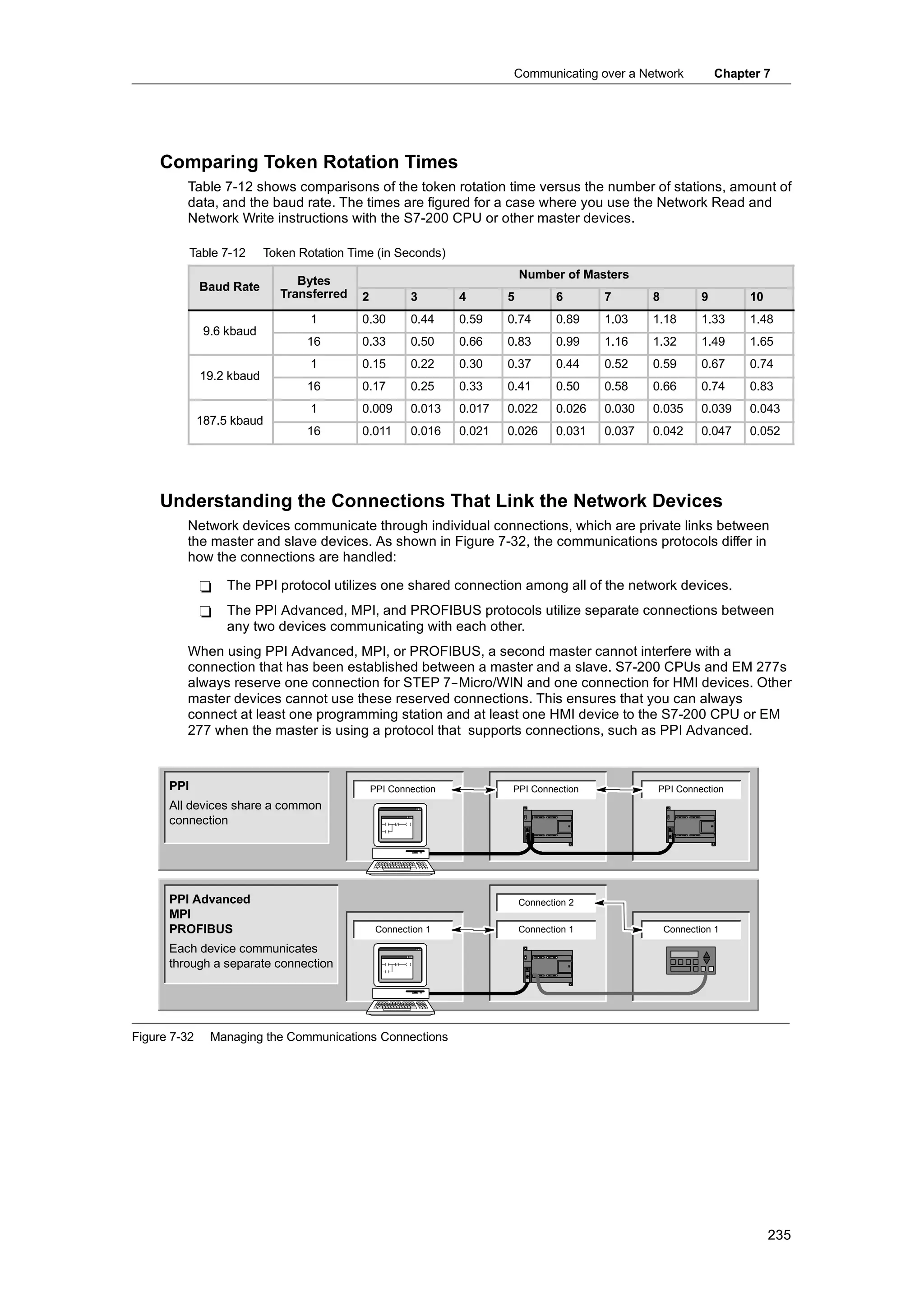
Addressing the Local and Expansion I/O
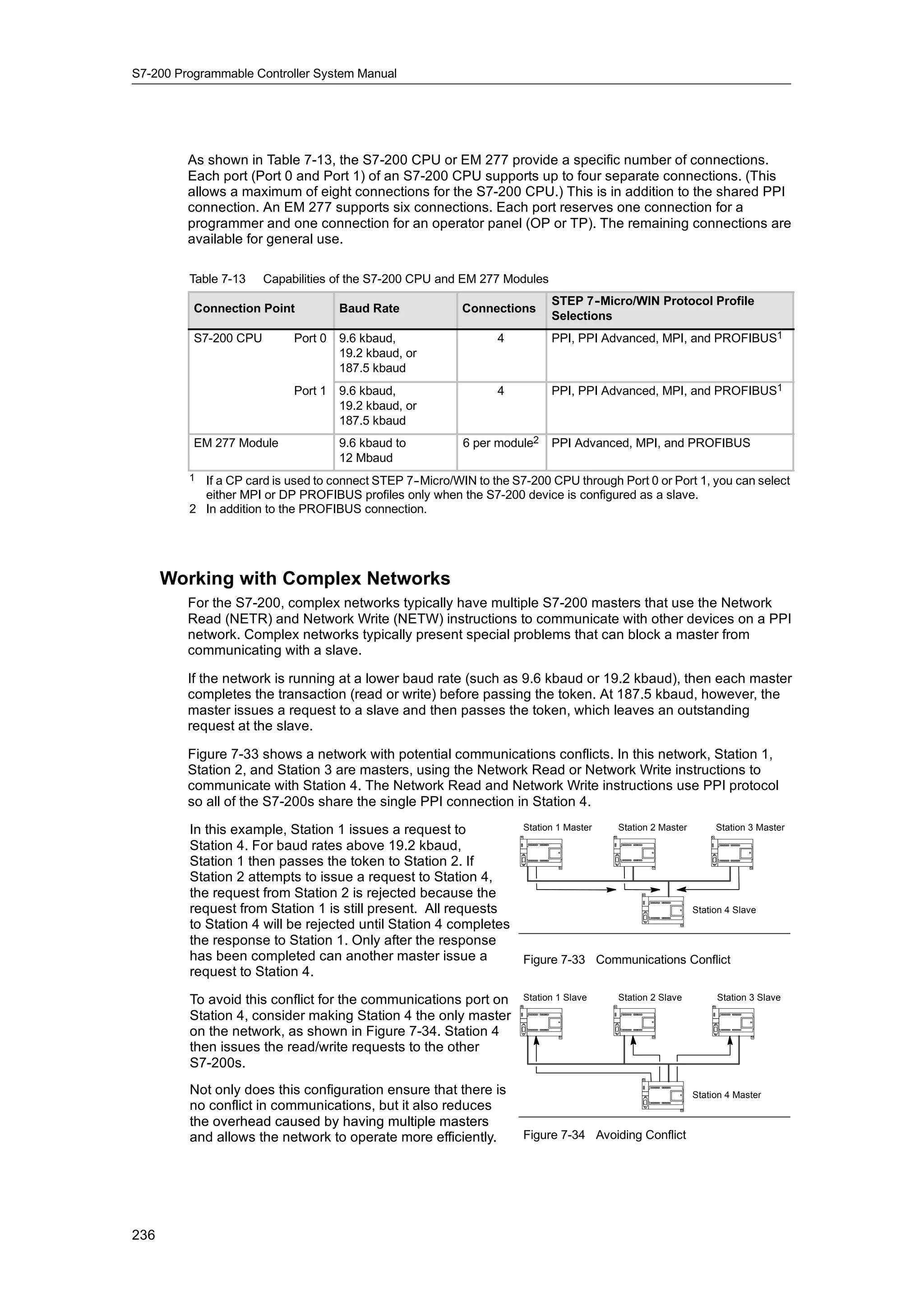
The local I/O provided by the CPU provides a fixed set of I/O addresses. You can add I/O points to
the S7-200 CPU by connecting expansion I/O modules to the right side of the CPU, forming an I/O
chain. The addresses of the points of the module are determined by the type of I/O and the
position of the module in the chain, with respect to the preceding input or output module of the
same type. For example, an output module does not affect the addresses of the points on an input
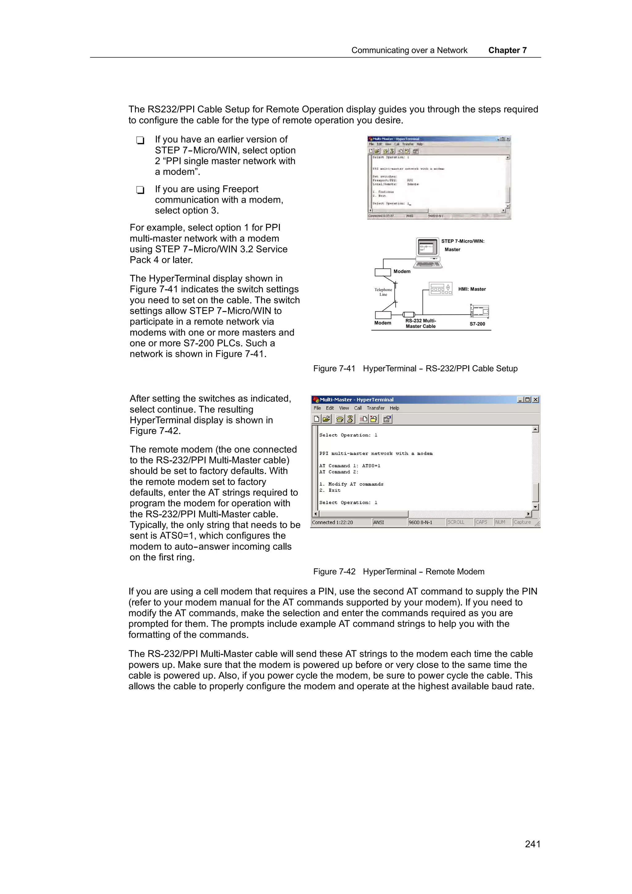
module, and vice versa. Likewise, analog modules do not affect the addressing of digital modules,
and vice versa.
Tip
Process-image register space for digital I/O is always reserved in increments of eight bits (one
byte). If a module does not provide a physical point for each bit of each reserved byte, these
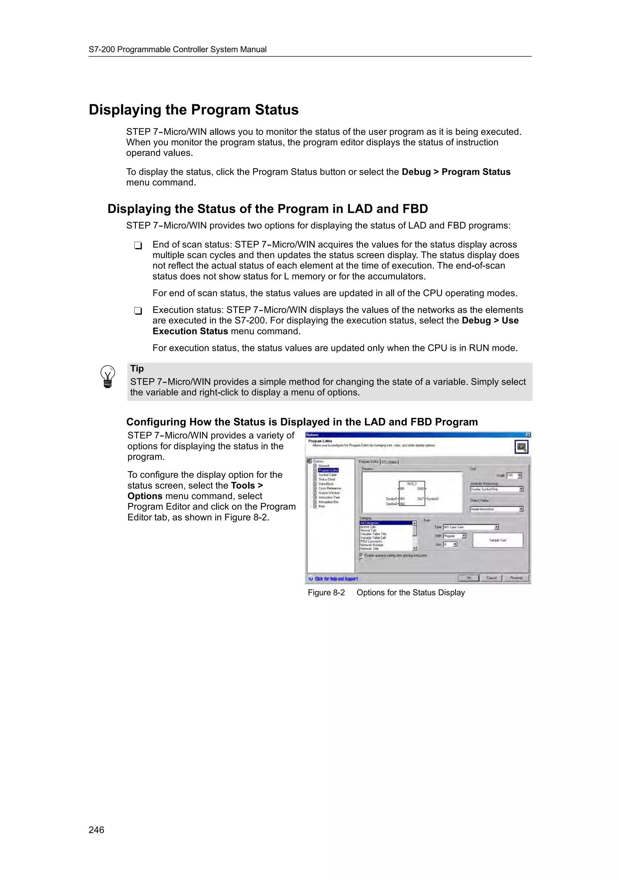
unused bits cannot be assigned to subsequent modules in the I/O chain. For input modules, the
unused bits are set to zero with each input update cycle.
Analog I/O points are always allocated in increments of two points. If a module does not provide
physical I/O for each of these points, these I/O points are lost and are not available for
assignment to subsequent modules in the I/O chain.
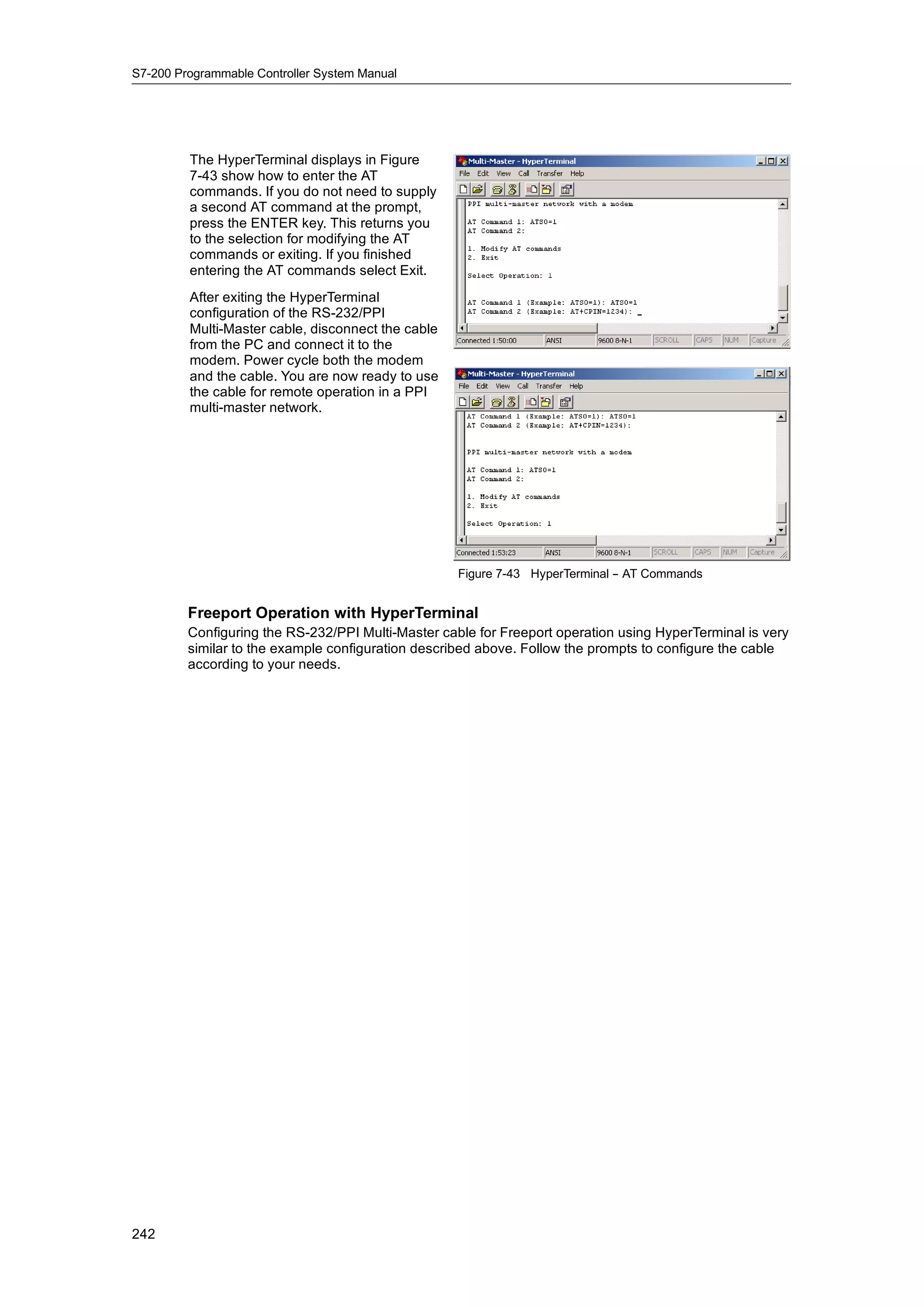
33](https://image.slidesharecdn.com/s7200systemmanualen-us-121009044520-phpapp02/75/S72-00-system-manual_en-us-47-2048.jpg)
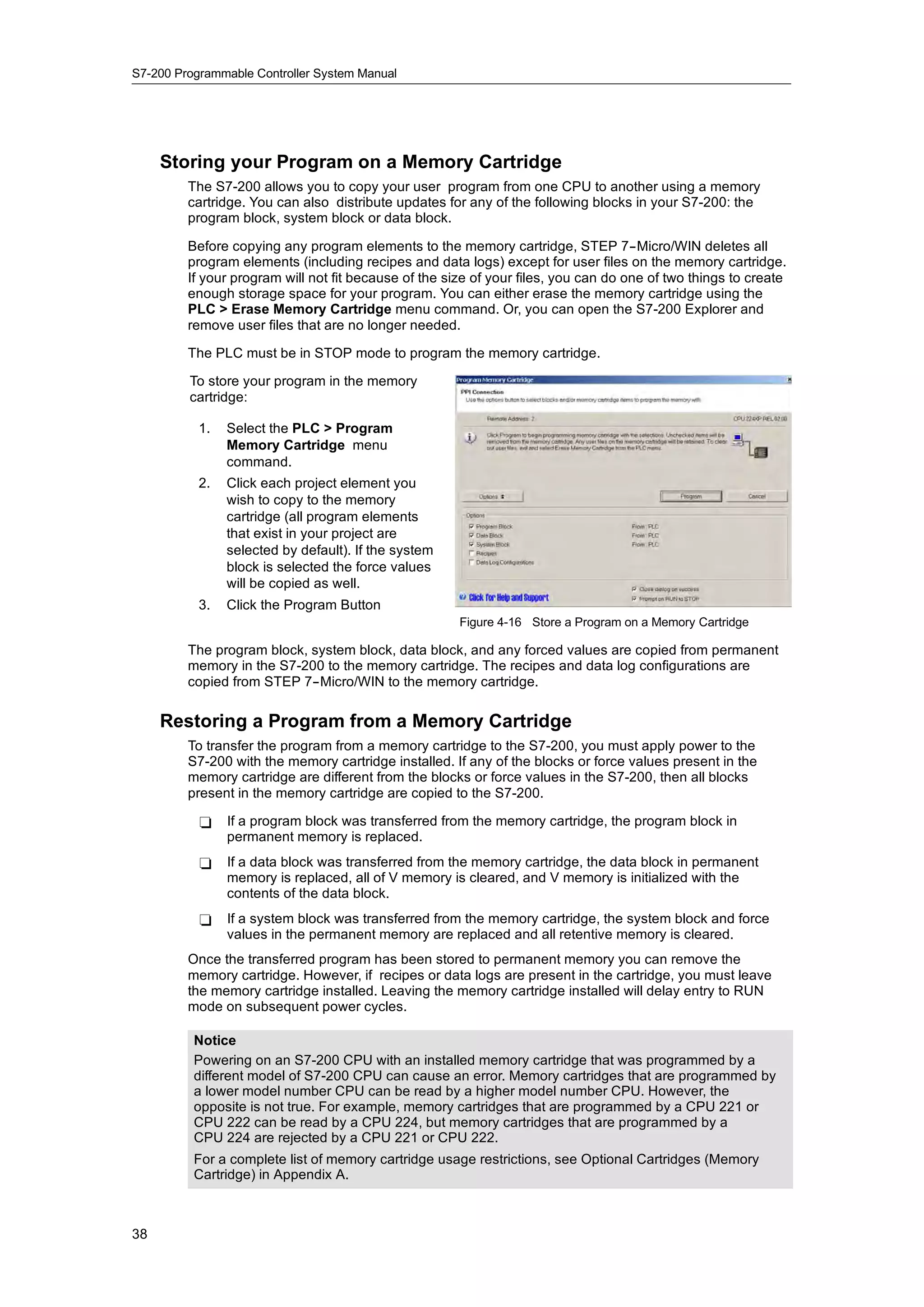
![S7-200 Programmable Controller System Manual
Converting Substrings to Numerical Values
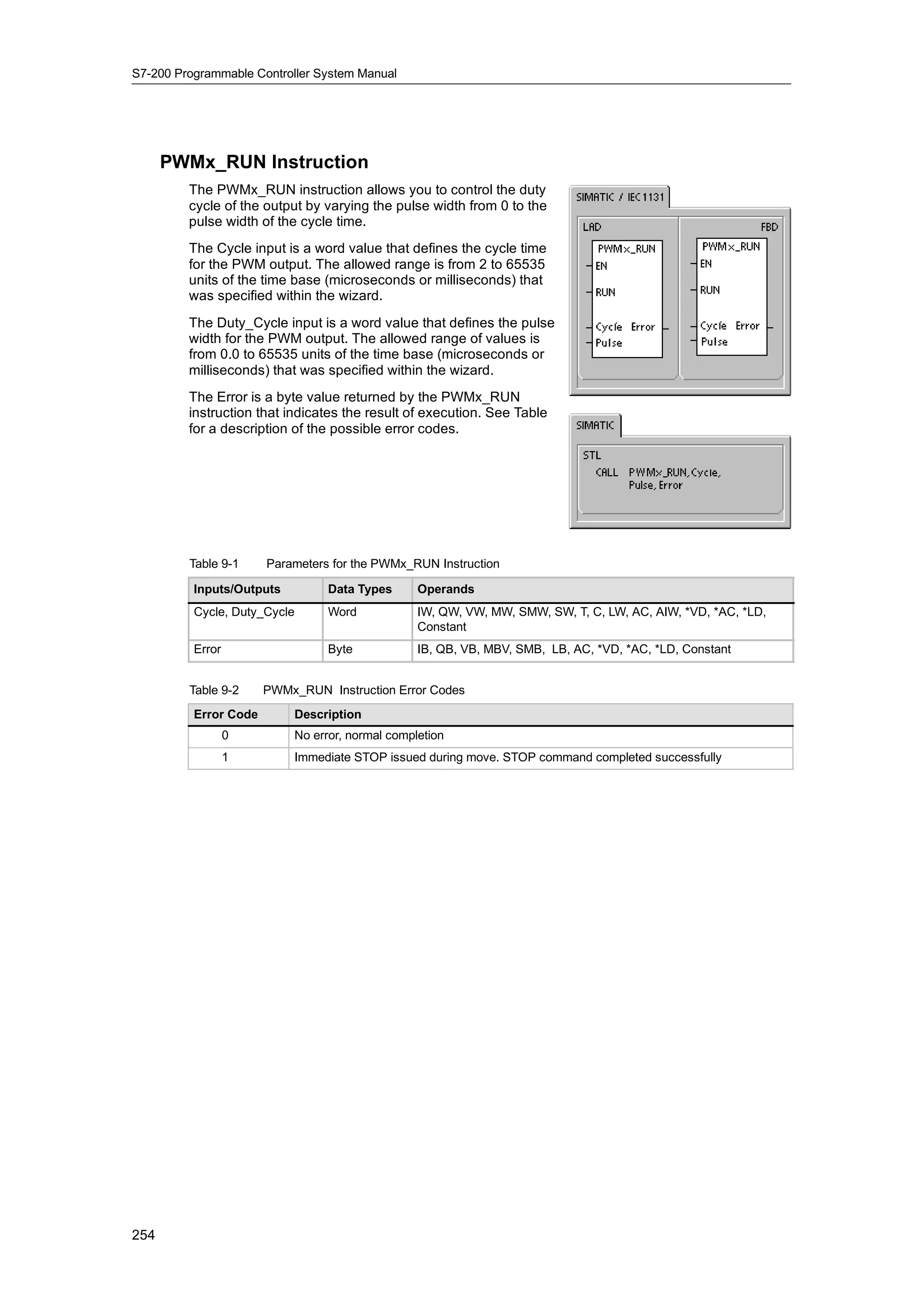
The Substring to Integer (STI), Substring to Double Integer
(STD), and Substring to Real (STR) instructions convert a
string value IN, starting at the offset INDX, to an integer,
double integer or real number value OUT .
Error conditions that set ENO = 0
H 0006 (indirect address)
H 0091 (operand out of range)
H 009B (index = 0)
H SM1.1 (overflow)
The Substring to Integer and Substring to Double Integer
convert strings with the following form:
[spaces] [+ or --] [digits 0 -- 9]
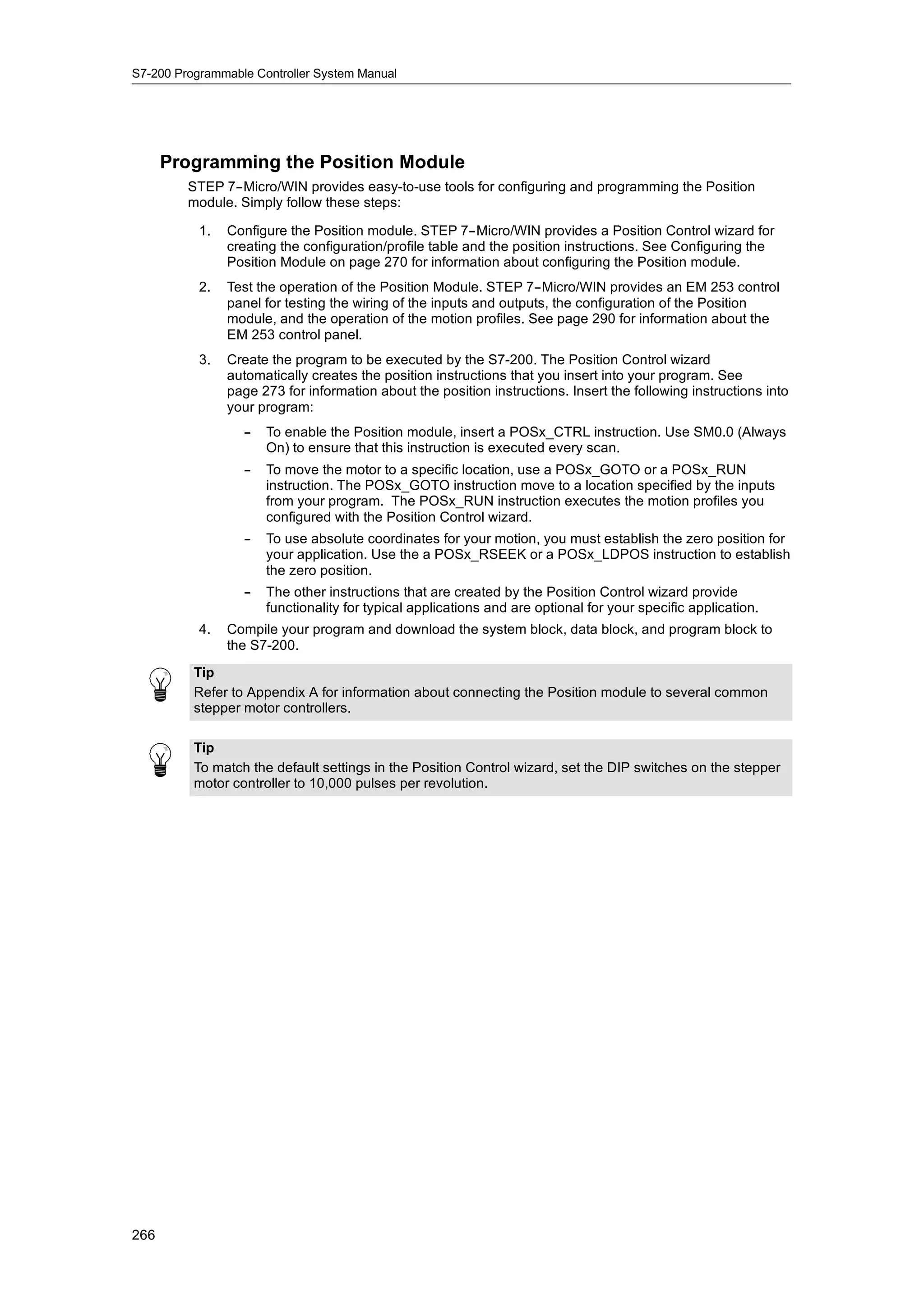
The Substring to Real instruction converts strings with the
following form: [spaces] [+ or --] [digits 0 -- 9] [. or ,] [digits
0 -- 9]
The INDX value is normally set to 1, which starts the
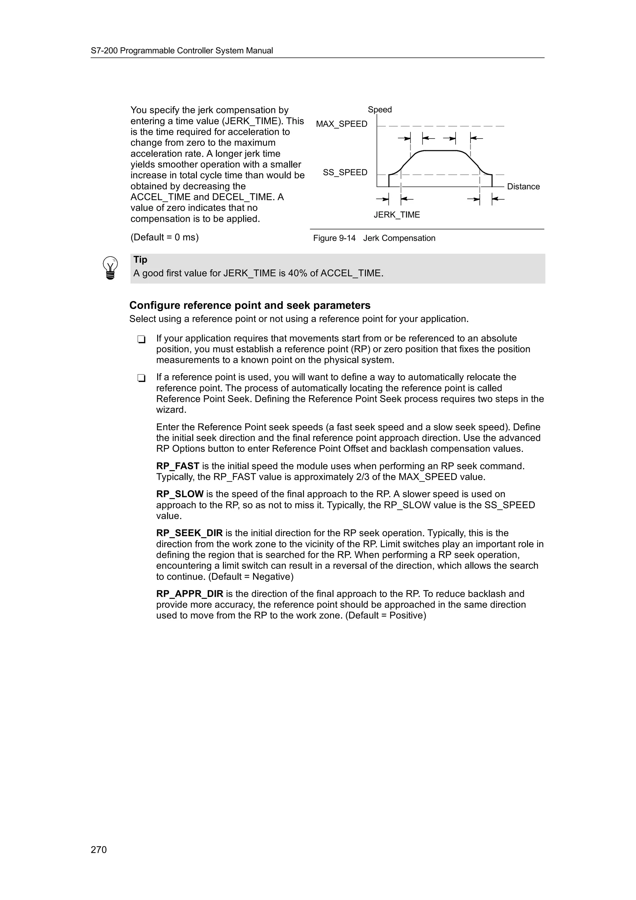
conversion with the first character of the string. The INDX
value can be set to other values to start the conversion at
different points within the string. This can be used when the
input string contains text that is not part of the number to be
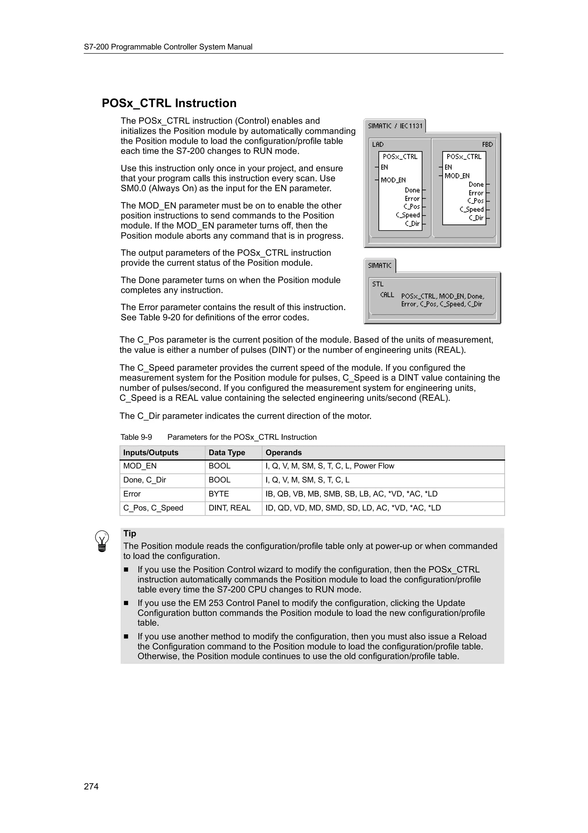
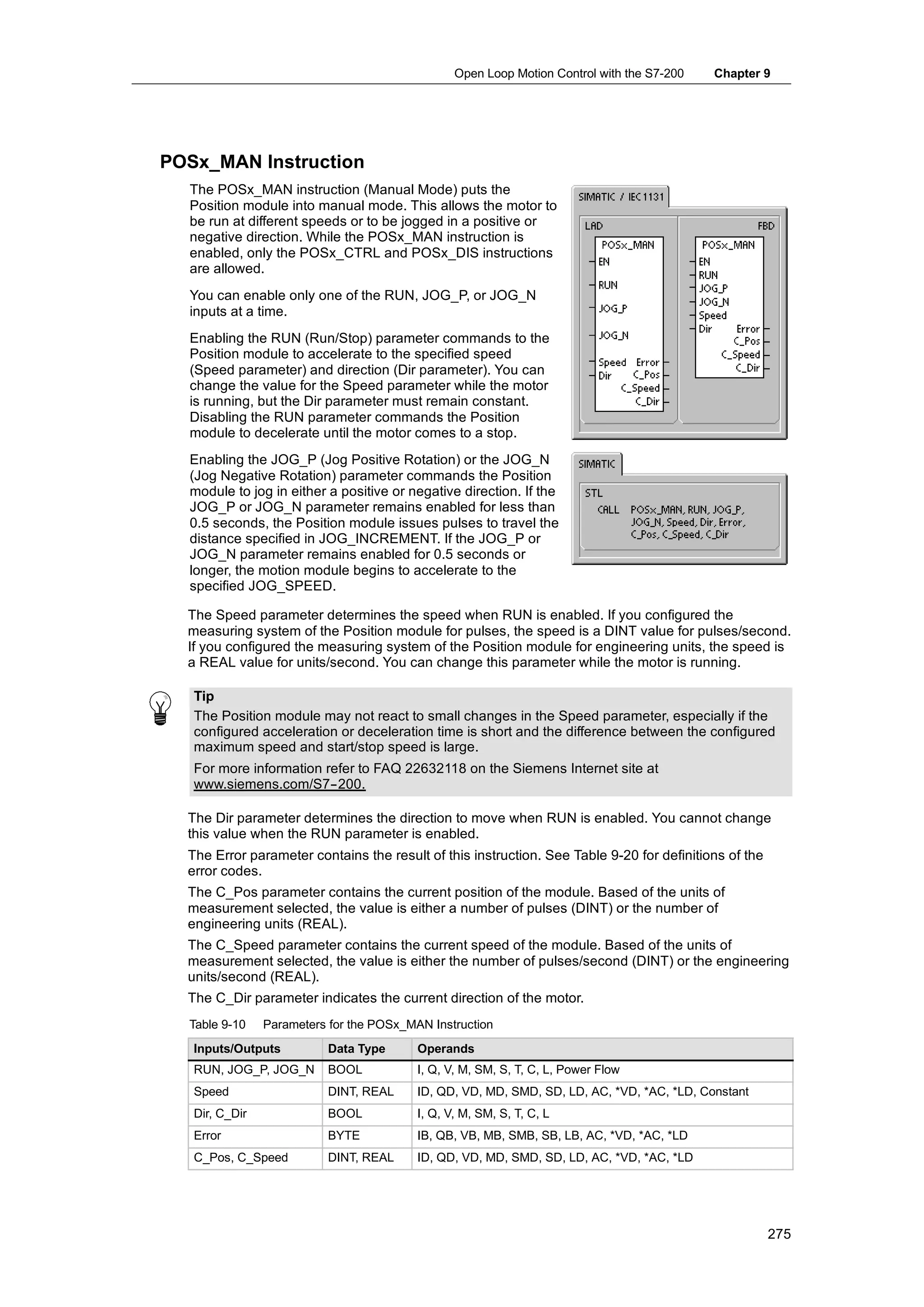
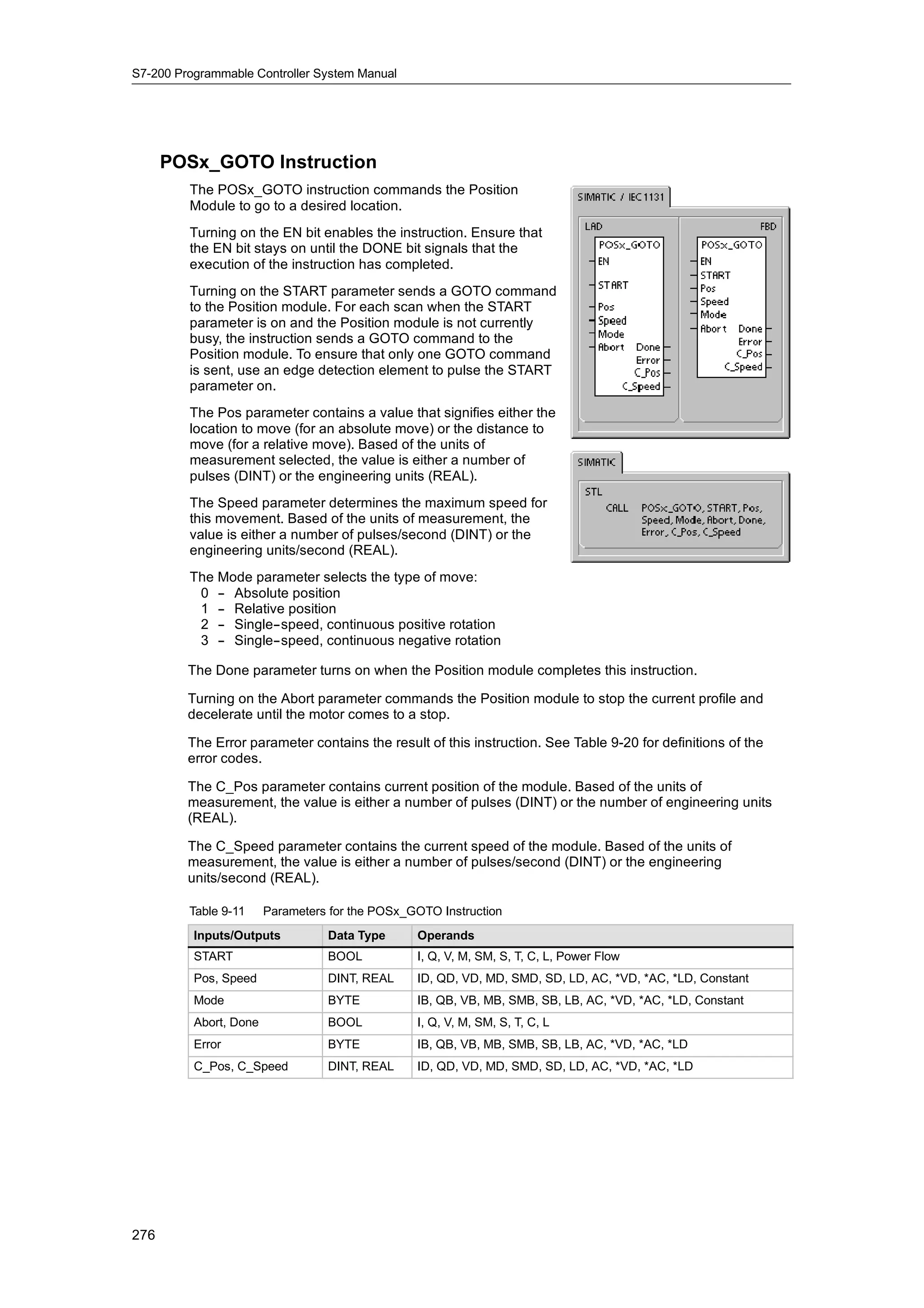
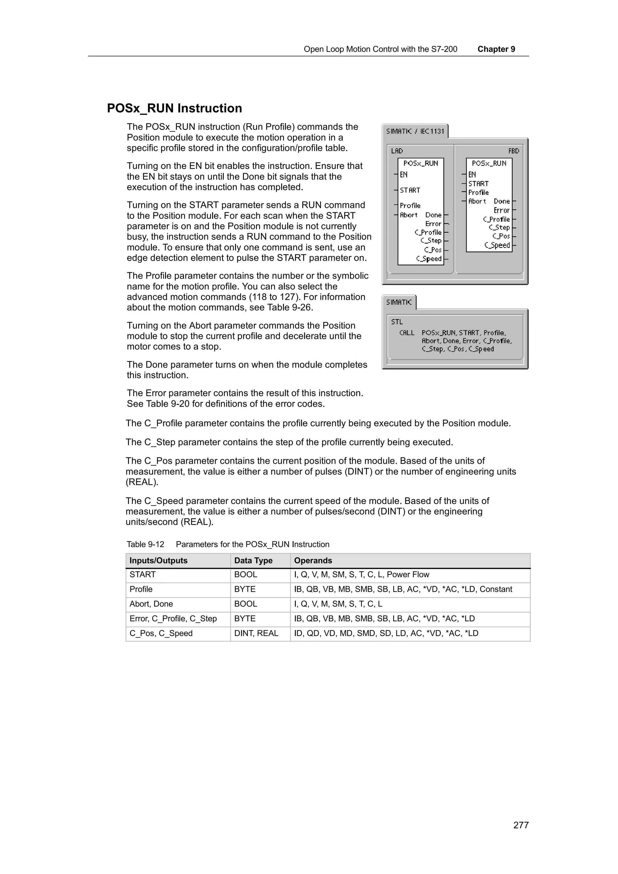
converted. For example, if the input string is “Temperature:
77.8”, you set INDX to a value of 13 to skip over the word
“Temperature: ” at the start of the string.
The Substring to Real instruction does not convert strings
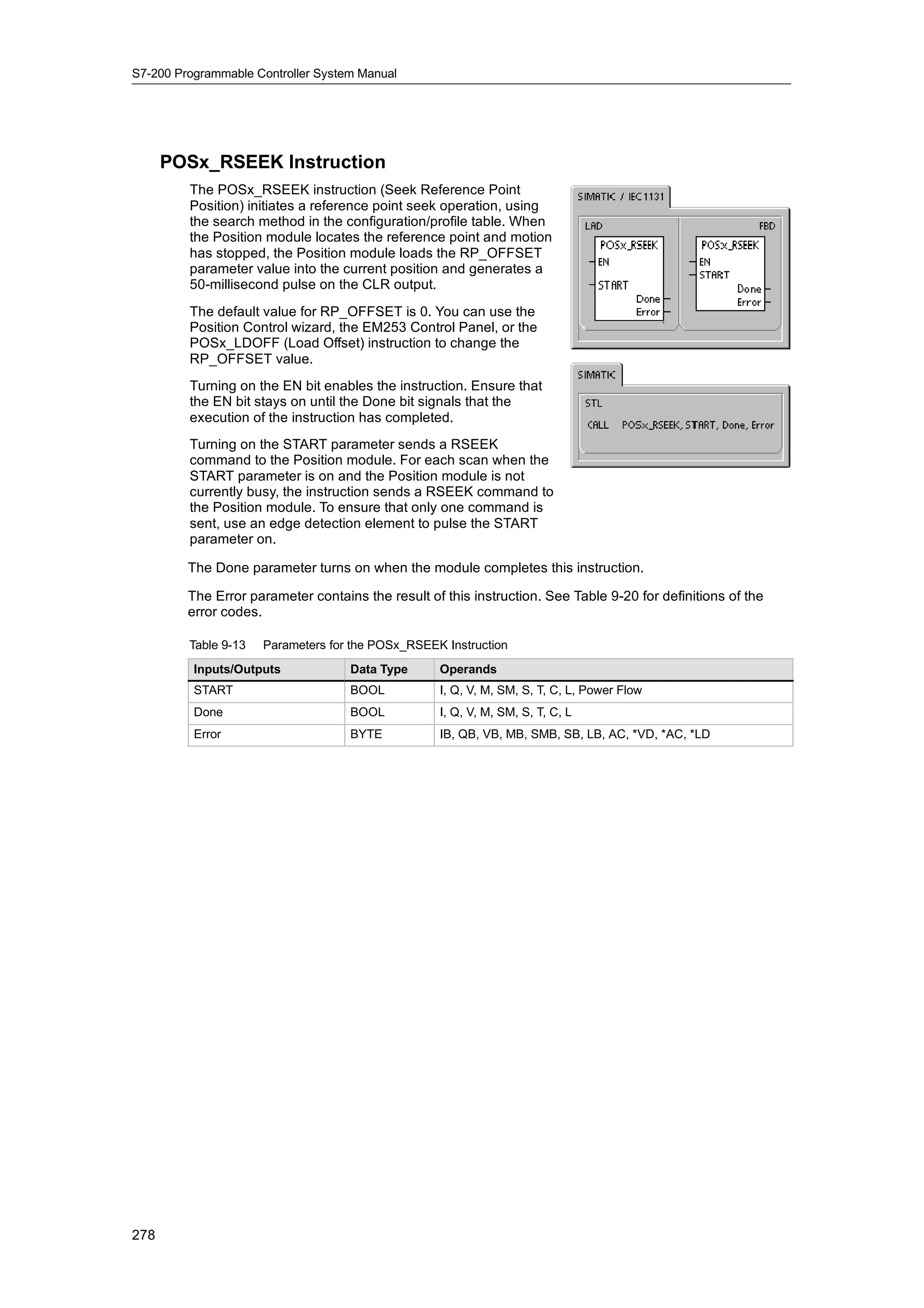
using scientific notation or exponential forms of real
numbers. The instruction does not produce an overflow
error (SM1.1) but converts the string to a real number up to
the exponential and then terminates the conversion. For
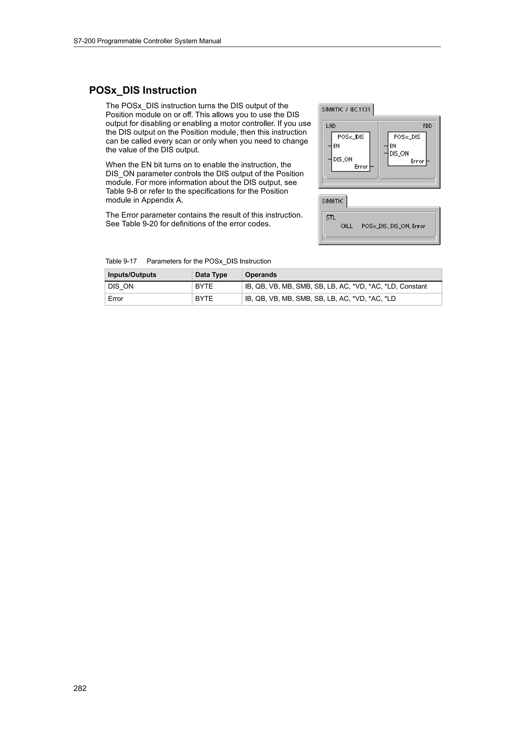
example, the string ‘1.234E6’ converts without errors to a
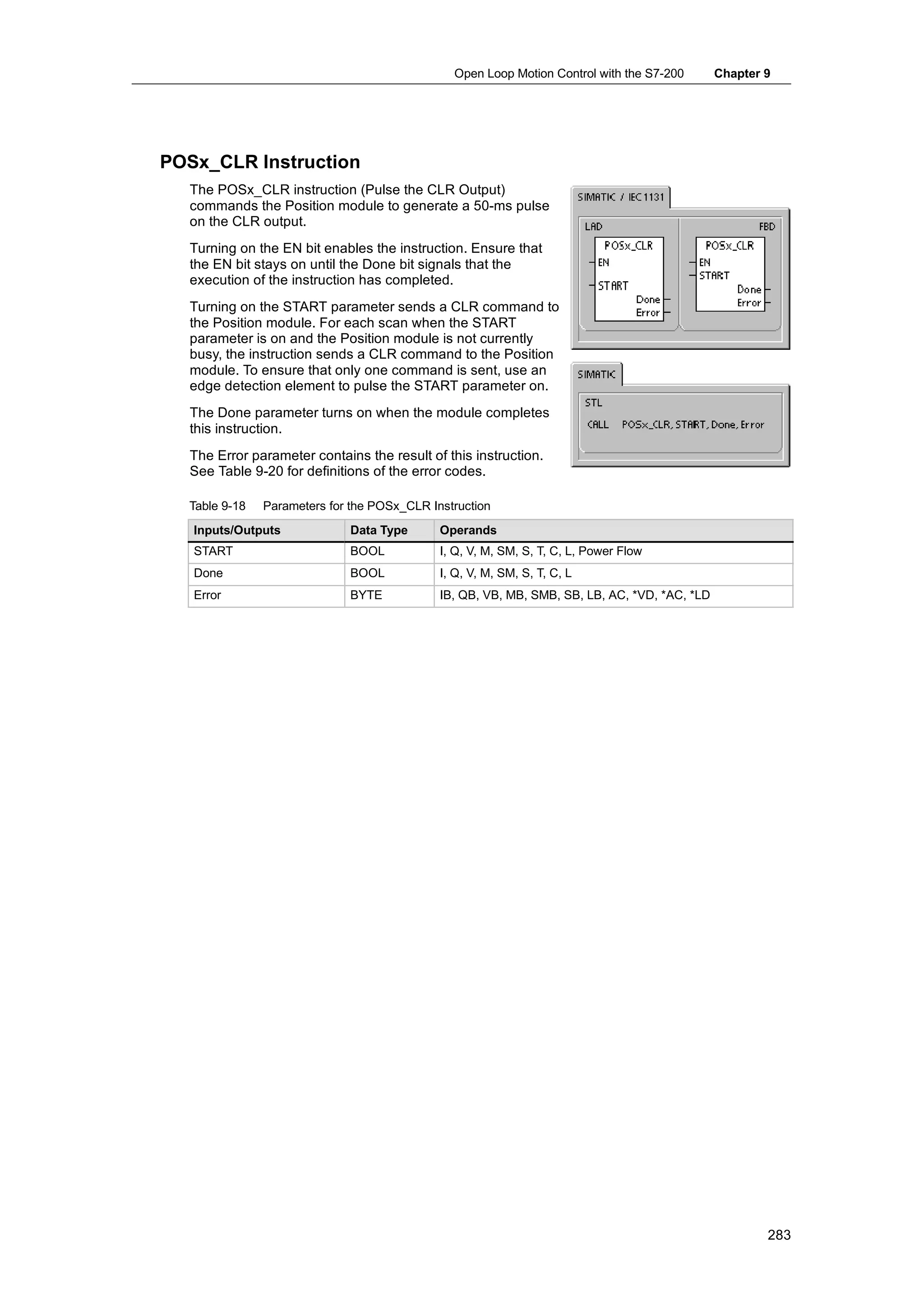
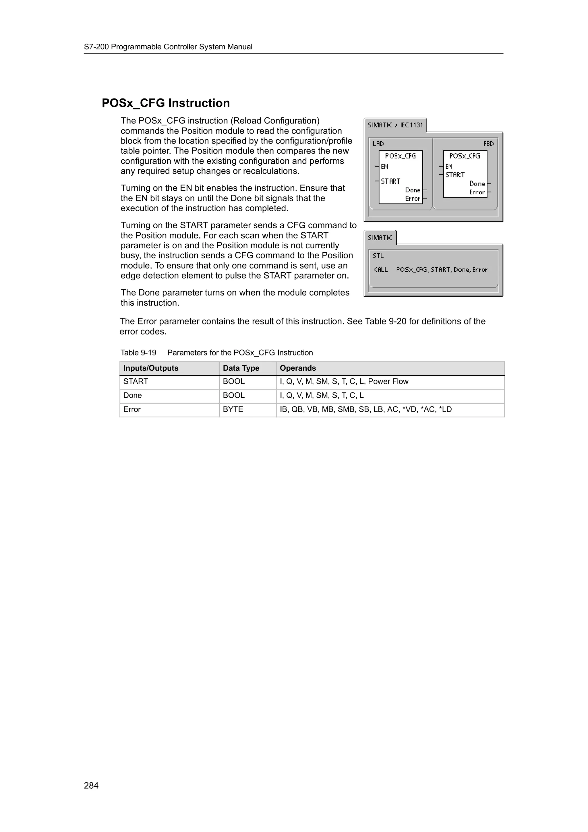
real value of 1.234.
The conversion is terminated when the end of the string is reached or when the first invalid
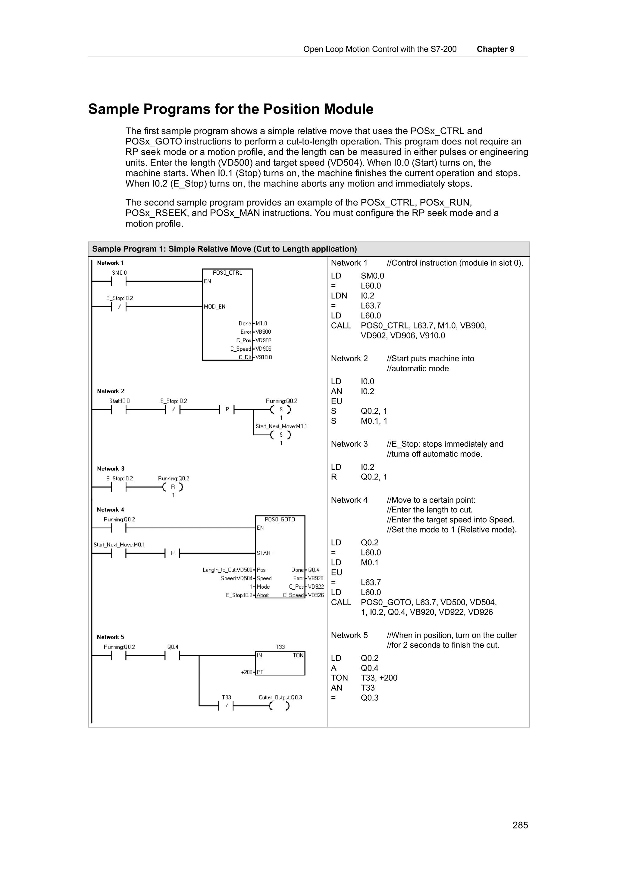
character is found. An invalid character is any character which is not a digit (0 -- 9).
The overflow error (SM1.1) is set whenever the conversion produces an integer value that is too
large for the output value. For example, the Substring to Integer instruction sets the overflow error
if the input string produces a value greater than 32767 or less than --32768.
The overflow error (SM1.1) is also set if no conversion is possible when the input string does not
contain a valid value. For example, if the input string contains ‘A123’, the conversion instruction
sets SM1.1 (overflow) and the output value remains unchanged.
Table 6-20 Valid Operands for the Instructions That Convert Substrings to Numerical Values
Inputs/Outputs Data Type Operands
IN STRING IB, QB, VB, MB, SMB, SB, LB, *VD, *LD, *AC, Constant
INDX BYTE VB, IB, QB, MB, SMB, SB, LB, AC, *VD, *LD, *AC, Constant
OUT INT VW, IW, QW, MW, SMW, SW, T, C, LW, AC, AQW, *VD, *LD, *AC
DINT, REAL VD, ID, QD, MD, SMD, SD, LD, AC, *VD, *LD, *AC
110](https://image.slidesharecdn.com/s7200systemmanualen-us-121009044520-phpapp02/75/S72-00-system-manual_en-us-124-2048.jpg)
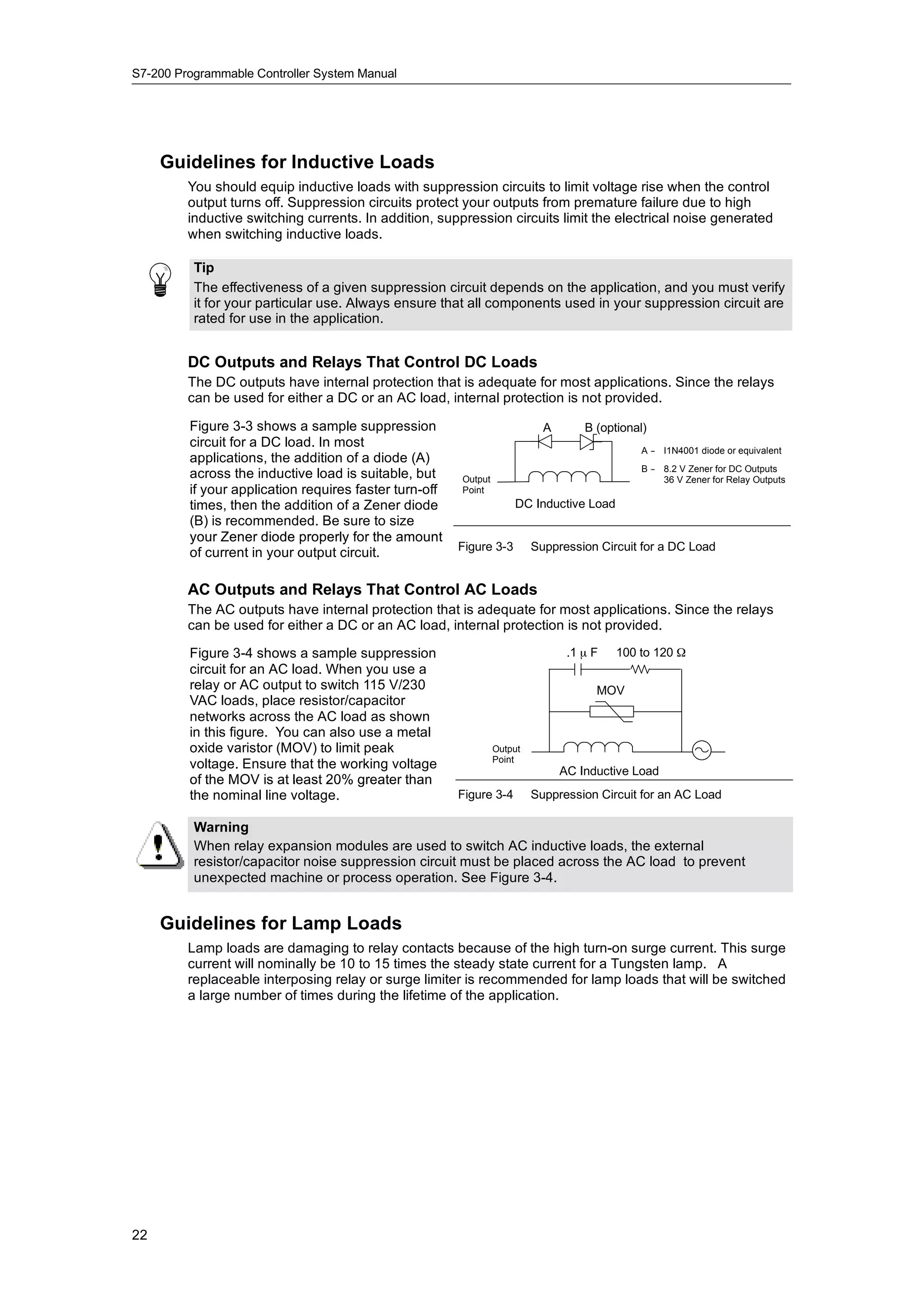
![S7-200 Programmable Controller System Manual
Use the following equation to compute the address of the most significant bit of the Shift Register
(MSB.b):
MSB.b = [(Byte of S_BIT) + ([N] - 1 + (bit of S_BIT)) / 8].[remainder of the division by 8]
-
For example: if S_BIT is V33.4 and N is 14, the Shift Minus, S_BIT
following calculation shows that the MSB.b is V35.1. Length = --14 MSB LSB
V33 7 4 0
MSB.b = V33 + ([14] -- 1 +4)/8
= V33 + 17/8
= V33 + 2 with a remainder of 1 V34 7 0
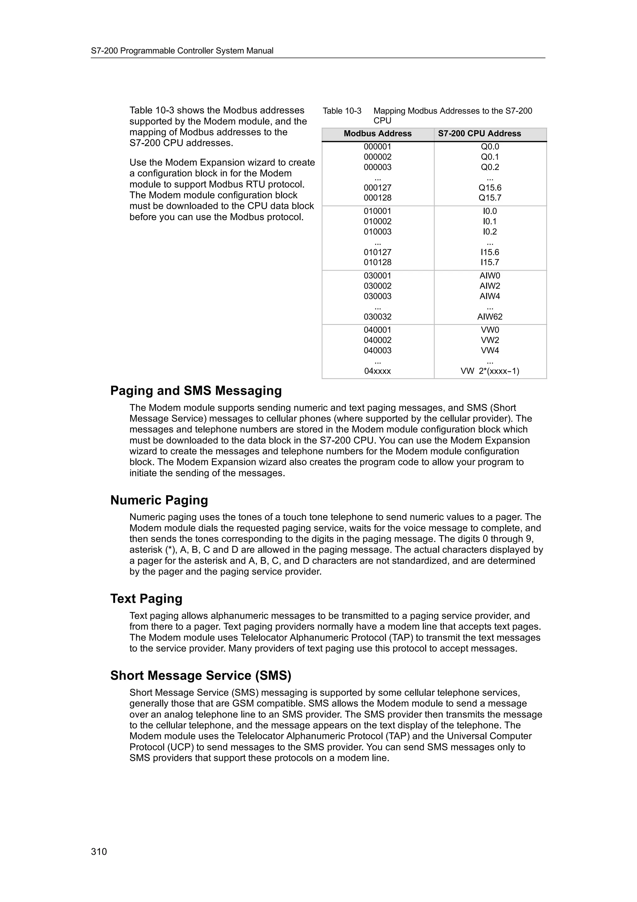
= V35.1
On a Shift Minus, indicated by a negative value of V35 7 1 0
length (N), the input data shifts into the most
significant bit of the Shift Register, and shifts out of
MSB of Shift Register
the least significant bit (S_BIT). The data shifted out
is then placed in the overflow memory bit (SM1.1). Shift Plus, S_BIT
MSB LSB
Length = 14
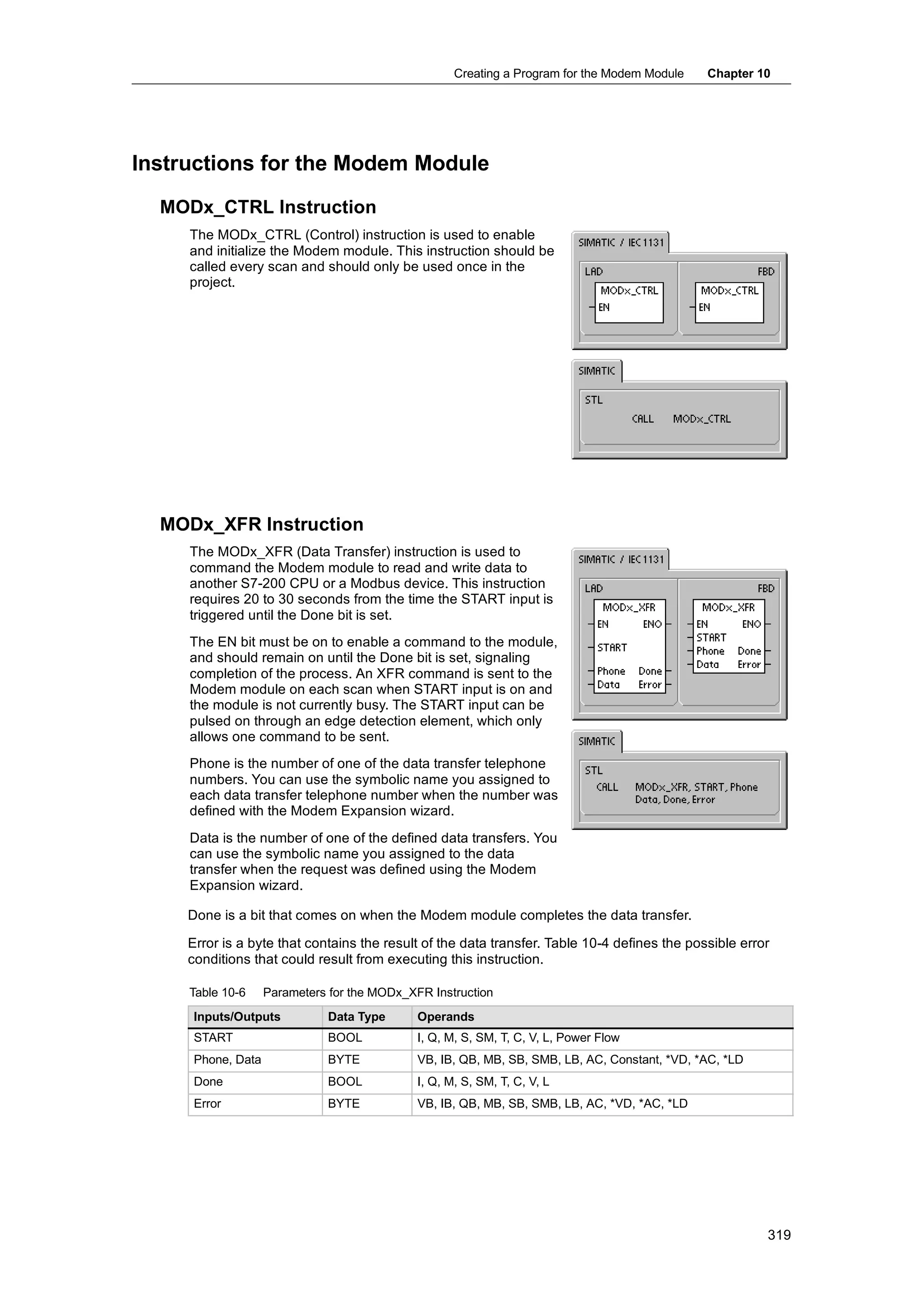
On a Shift Plus, indicated by a positive value of V33 7 4 0
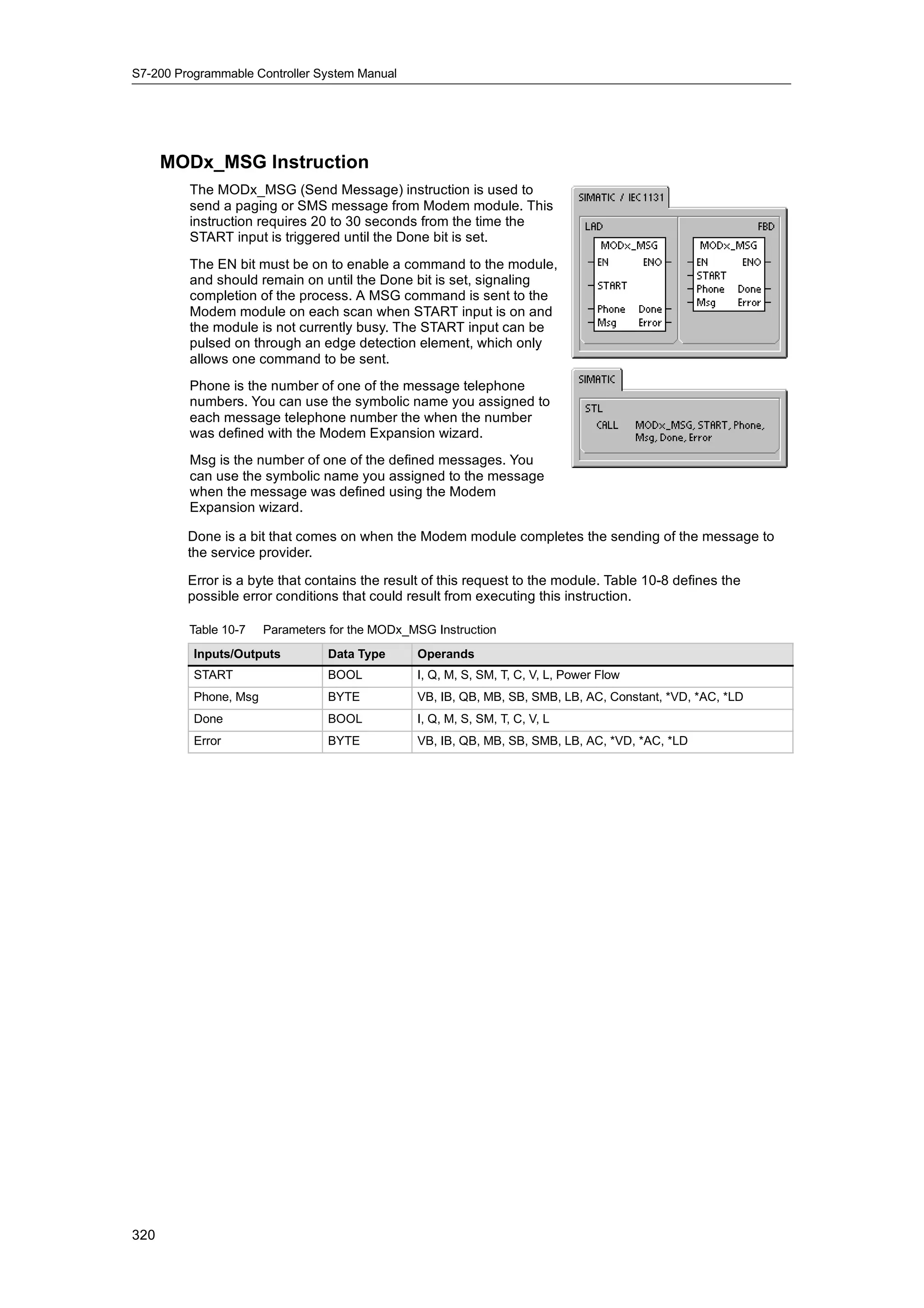
length (N), the input data (DATA) shifts into the least
significant bit of the Shift Register, specified by the V34 7 0
S_BIT, and out of the most significant bit of the Shift
Register. The data shifted out is then placed in the
V35 7 1 0
overflow memory bit (SM1.1).
The maximum length of the shift register is 64 bits, MSB of Shift Register
positive or negative. Figure 6-35 shows bit shifting
g g g
for
f negative and positive values of N
ti d iti l f N. Figure 6-35 Shift Register Entry and Exit
Example: Shift Register Bit Instruction
Network 1
LD I0.2
EU
SHRB I0.3, V100.0, +4
7 (MSB) 0 (LSB) S_BIT
Timing Diagram
Before V100 0 1 0 1 I0.3
first shift
I0.2
Overflow (SM1.1) x
S_BIT
Positive
transition (P) After V100 1 0 1 1 I0.3
first shift
I0.3 Overflow (SM1.1) 0
S_BIT
First shift Second shift After V100 0 1 1 0 I0.3
second
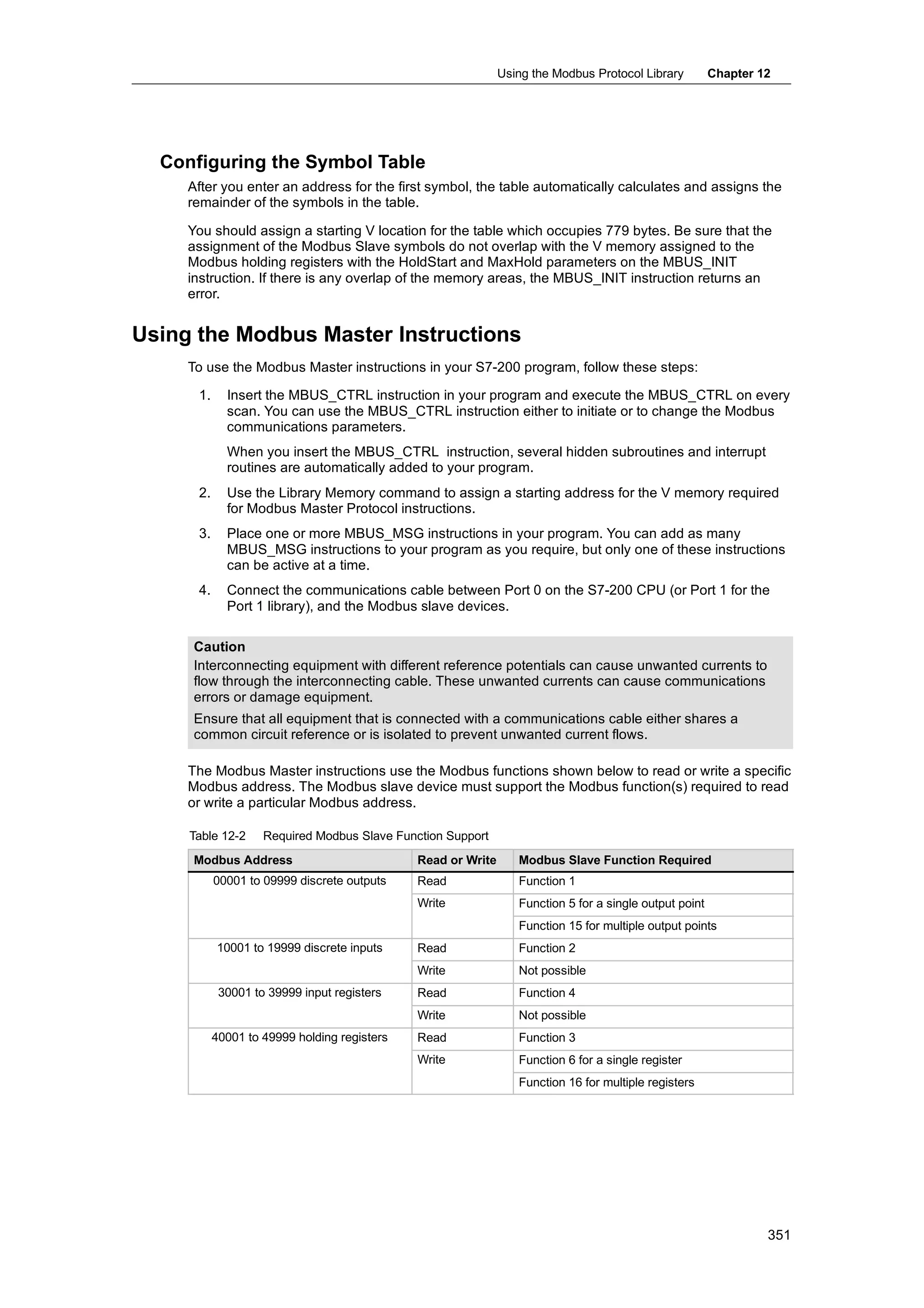
shift
Overflow (SM1.1) 1
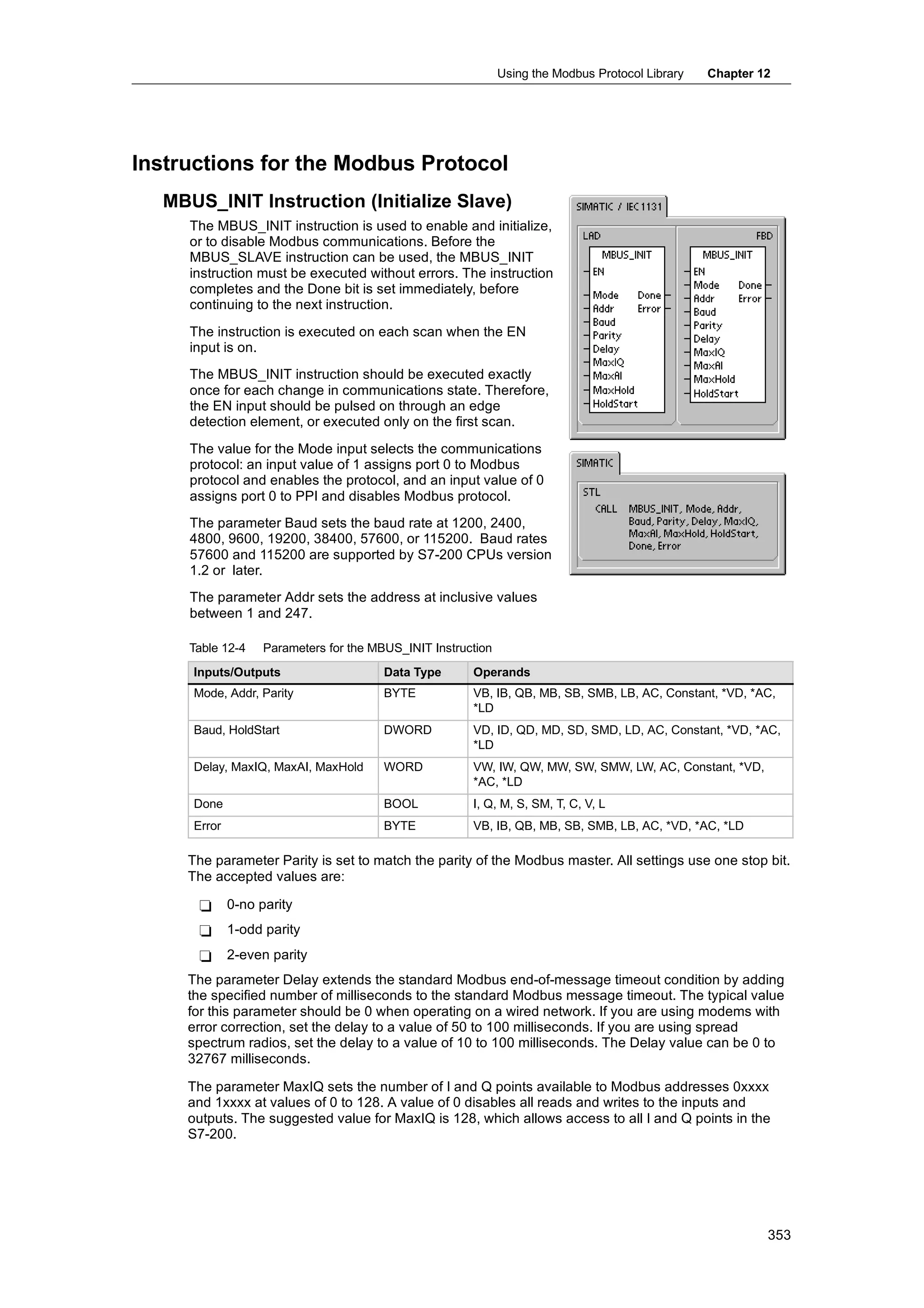
182](https://image.slidesharecdn.com/s7200systemmanualen-us-121009044520-phpapp02/75/S72-00-system-manual_en-us-196-2048.jpg)


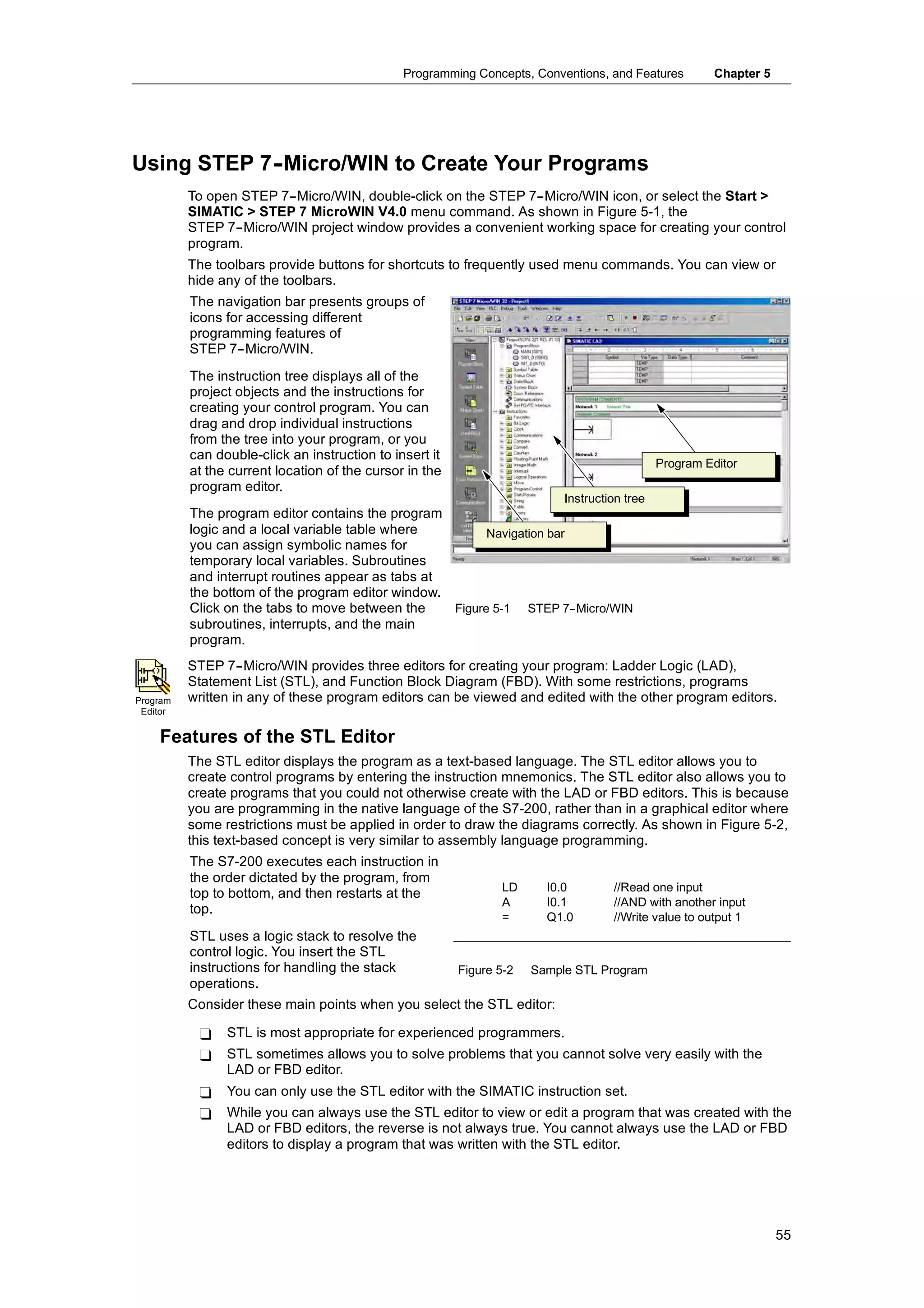
This manual provides information about installing and programming Siemens S7-200 Micro PLCs. It covers topics such as getting started, installing the S7-200 PLC, programming concepts and features, instructions, communicating over networks, troubleshooting, and application examples. The manual is designed for engineers and technicians working with S7-200 PLCs.