Downloaded 335 times

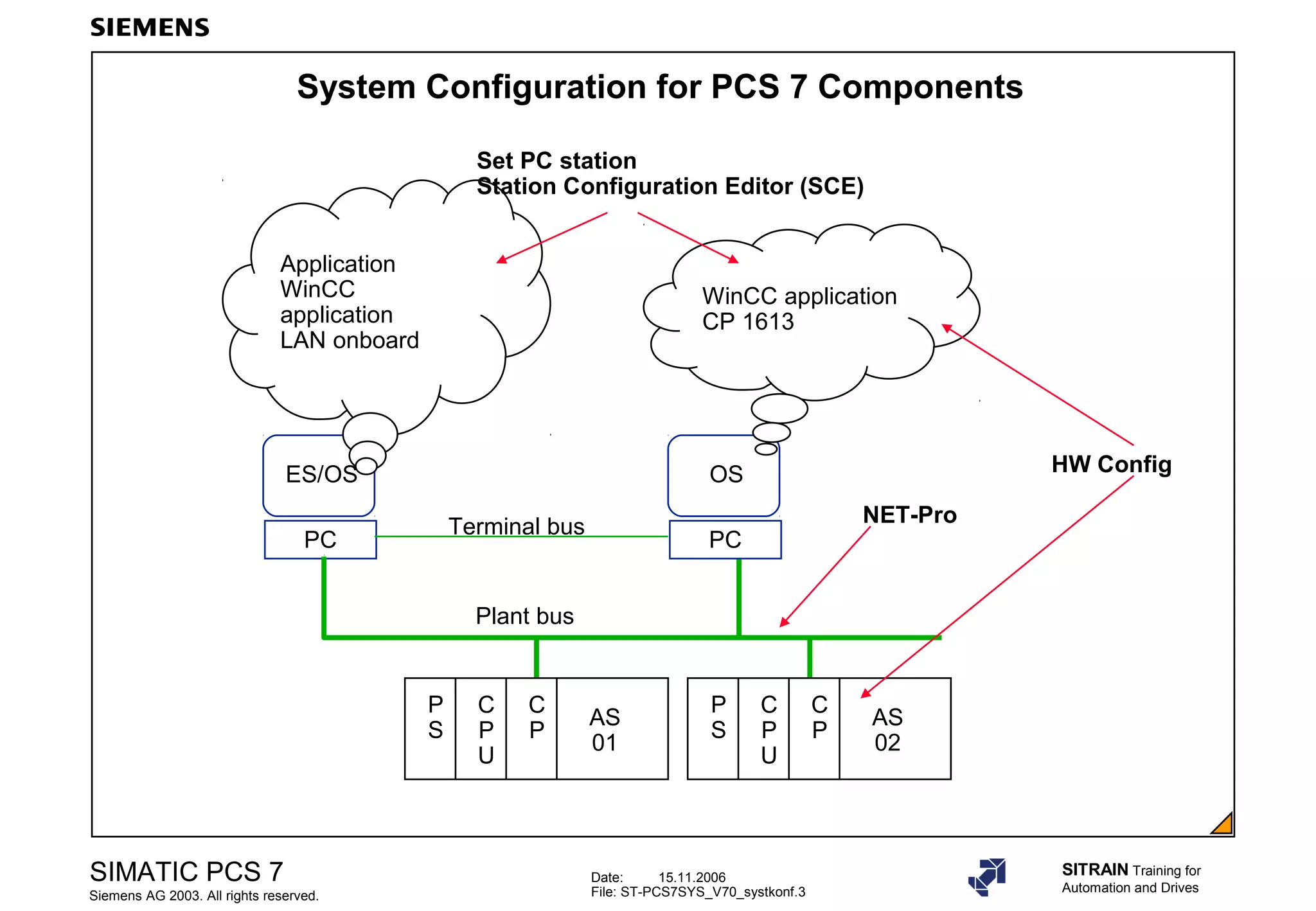
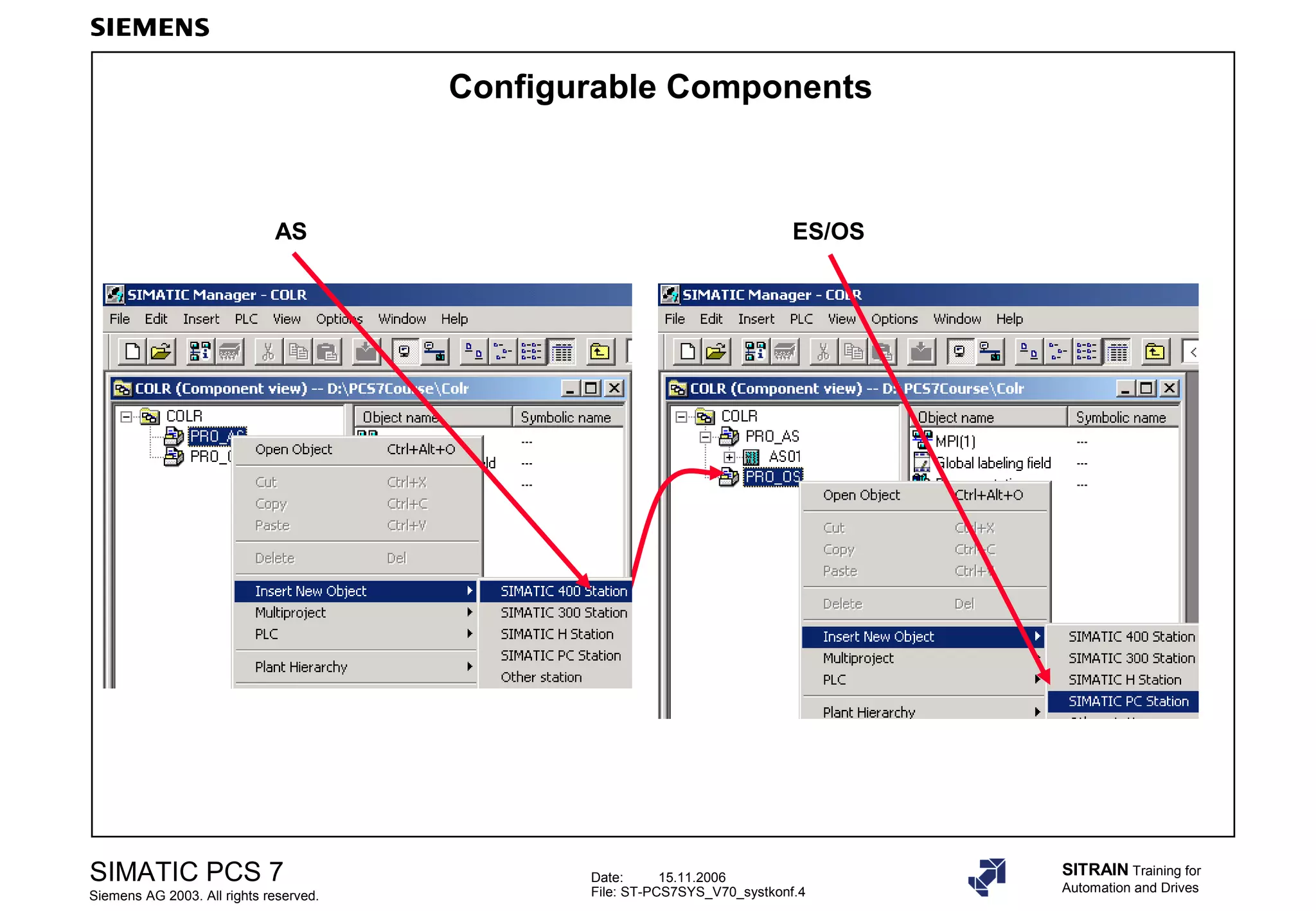
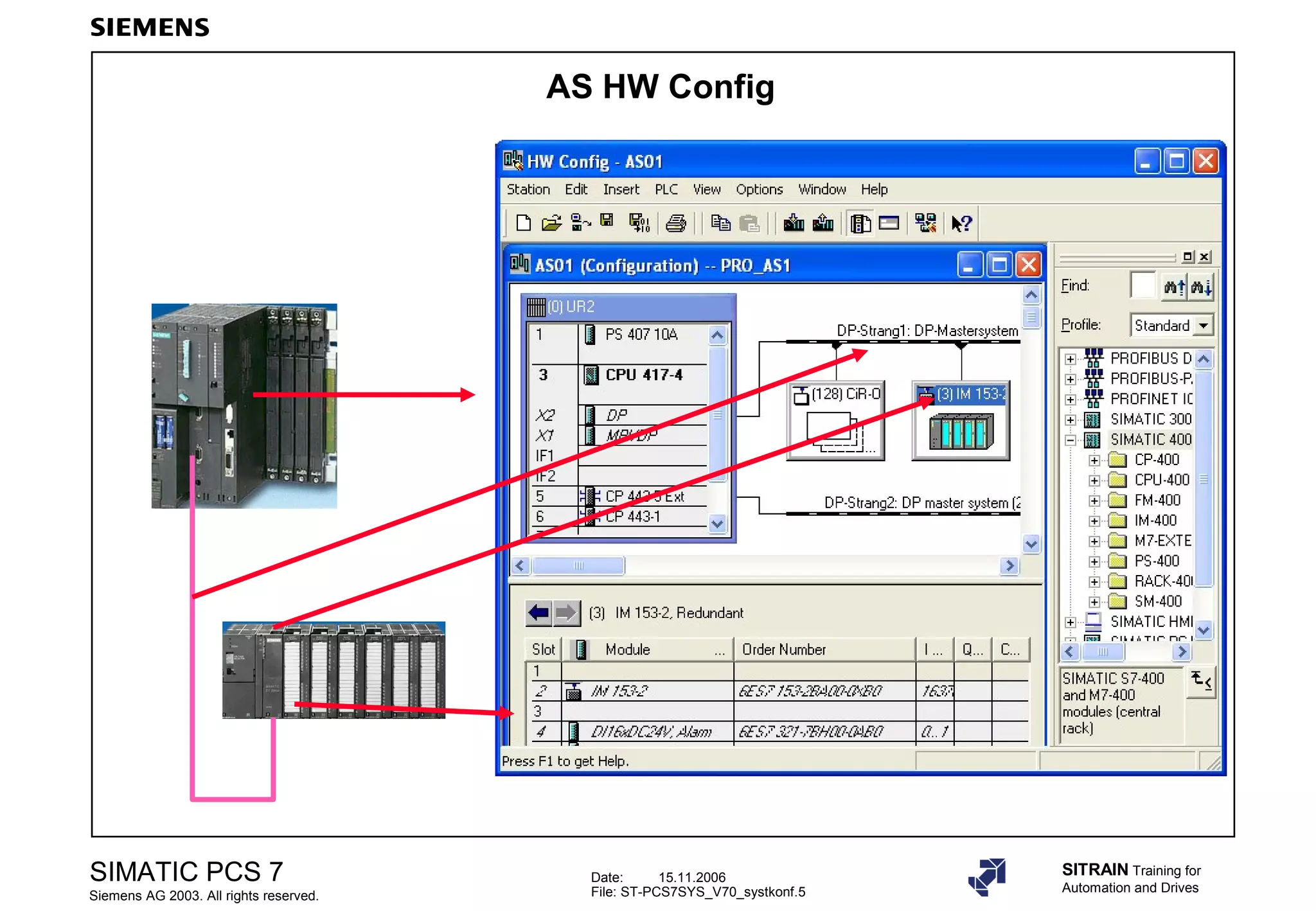


The document discusses configuration of SIMATIC PCS 7 components including: 1. Configuring automation systems (AS) using hardware configuration (HW Config) including configuring PROFIBUS DP, process image partitions, and symbolic channel names. 2. Configuring SIMATIC PC stations including setting modules, access points, and using the station configuration editor. 3. Configuring network connections between automation systems and OSs using NetPro.
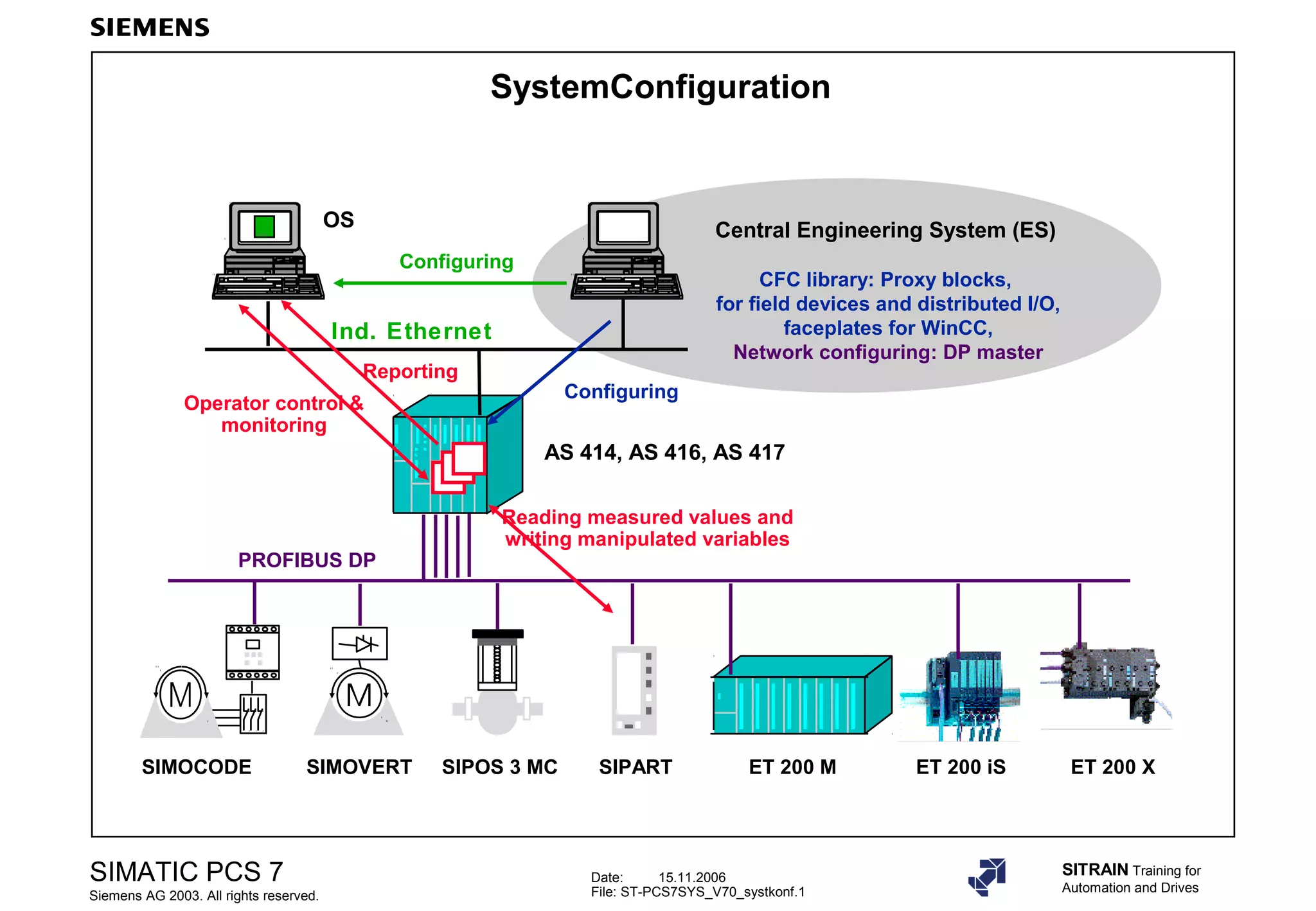
Introduction to SIMATIC PCS 7, network configuration, central engineering system, and operator monitoring.
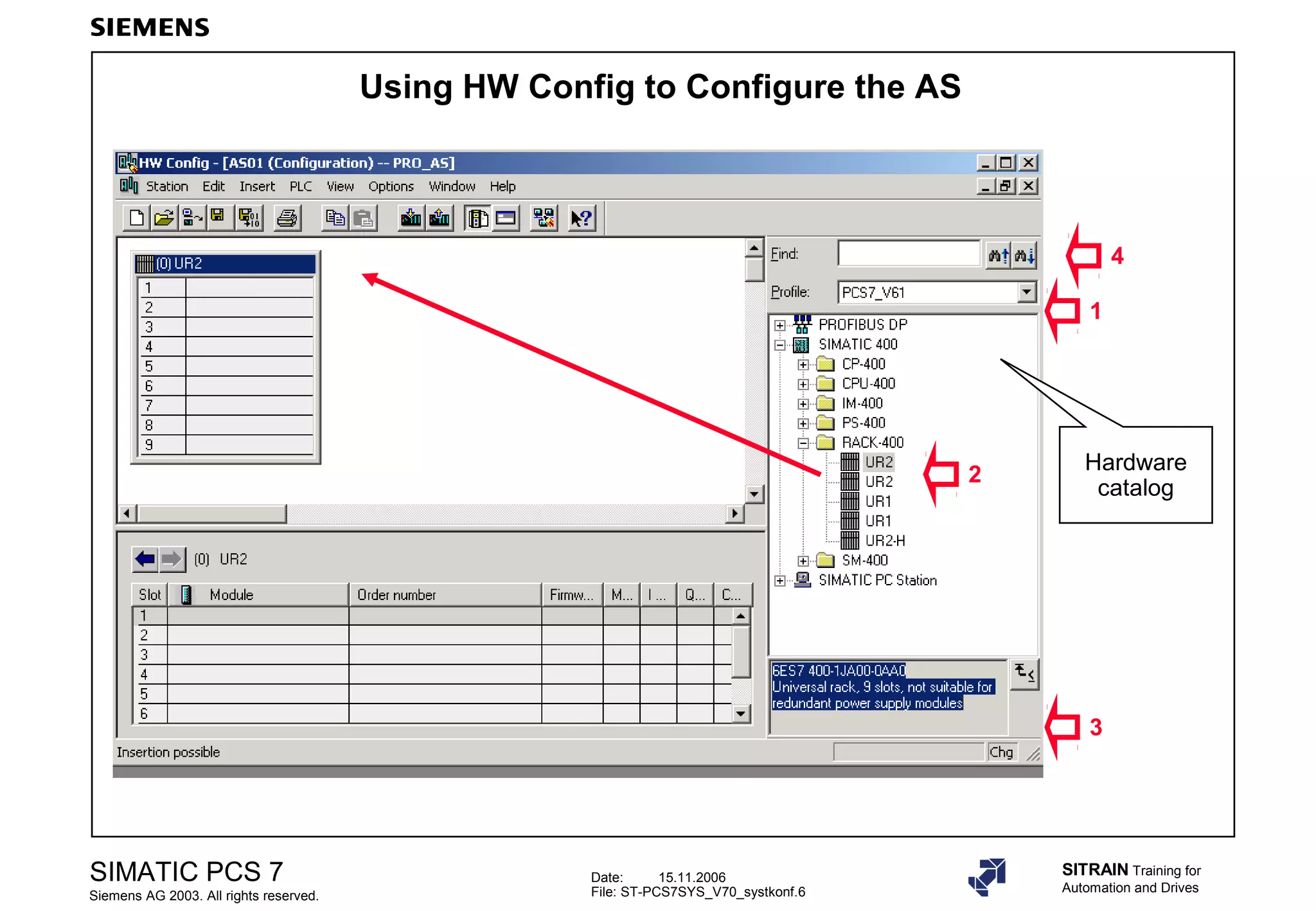
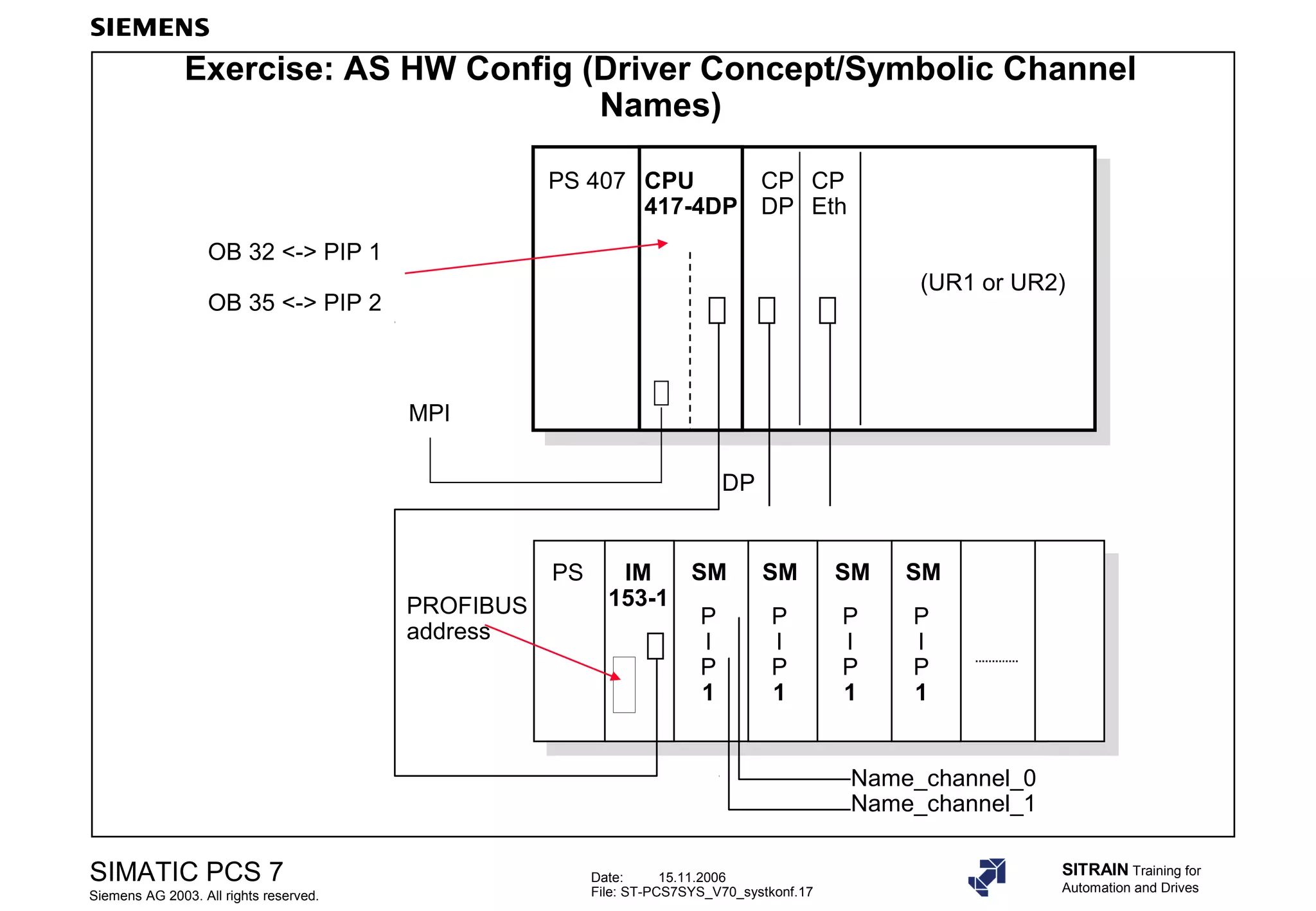
Details on AS HW Config for setting up hardware, including using the hardware catalog for configuration.
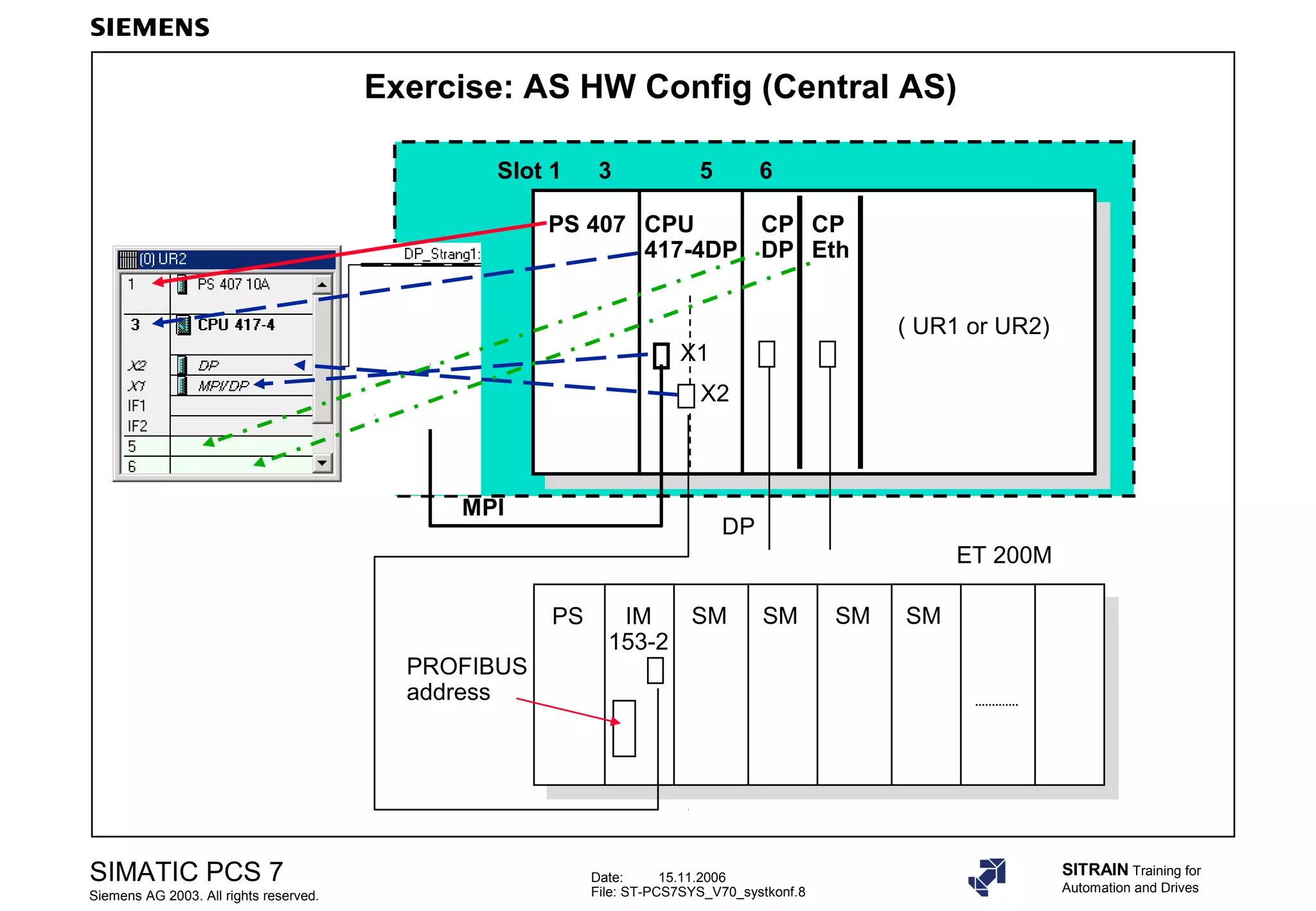
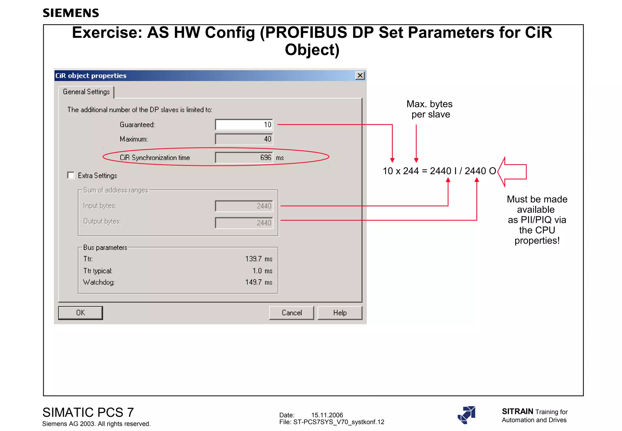
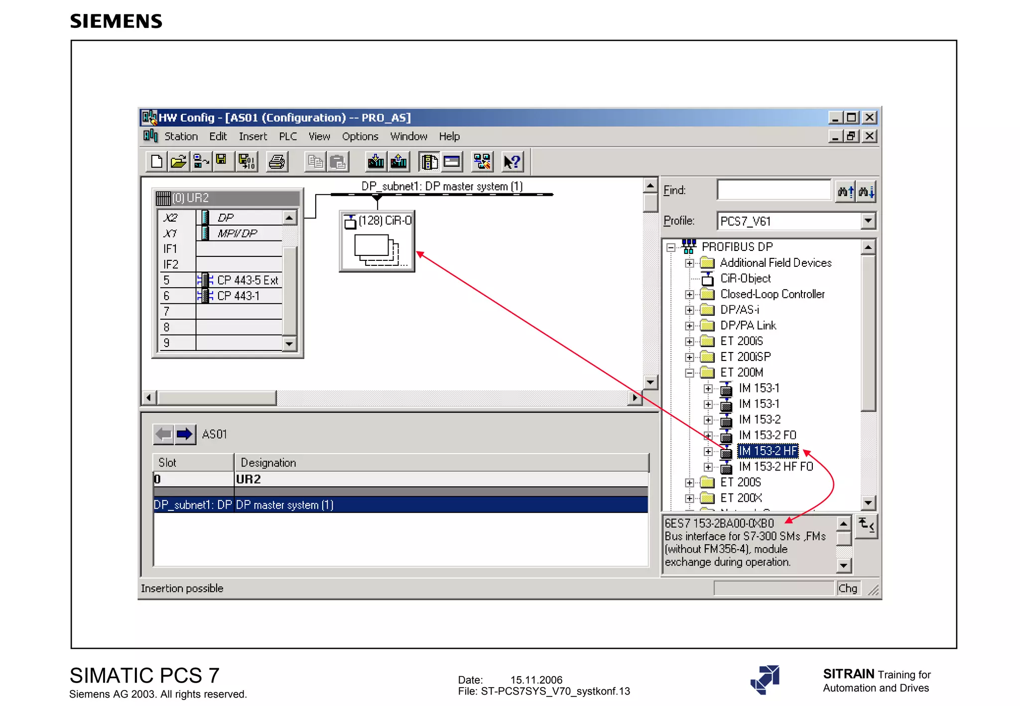
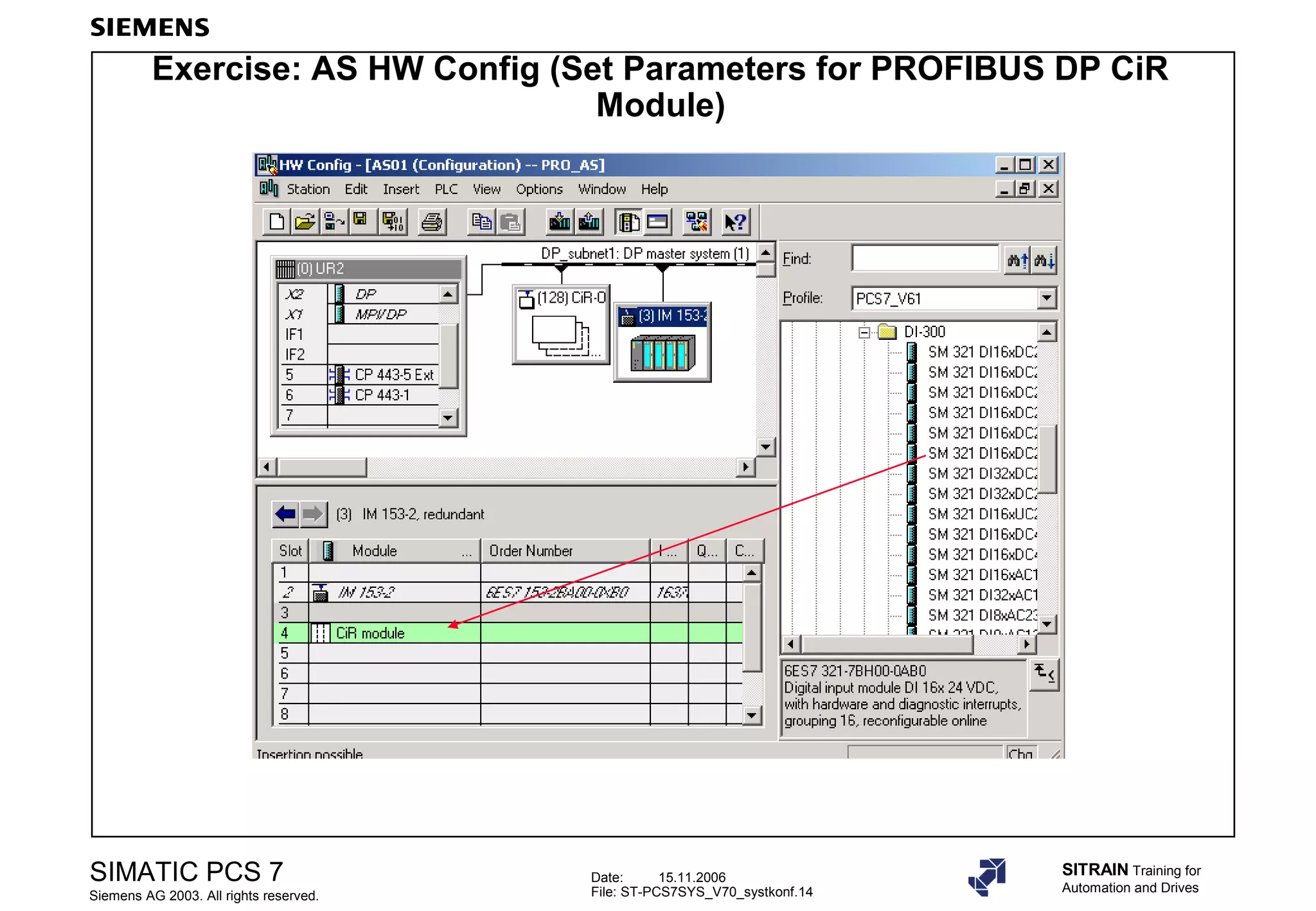
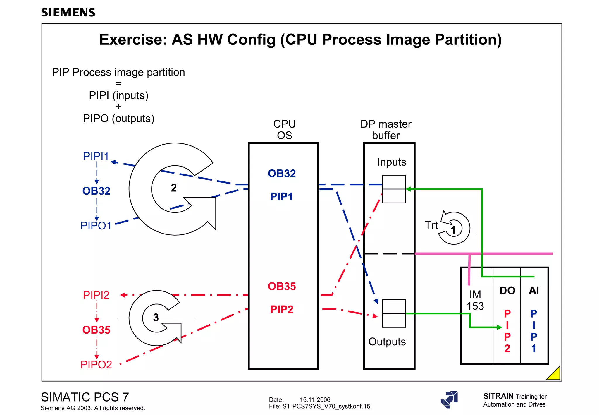
Practical exercises on configuration settings for AS, focusing on PROFIBUS DP and parameters like I/O bandwidth.
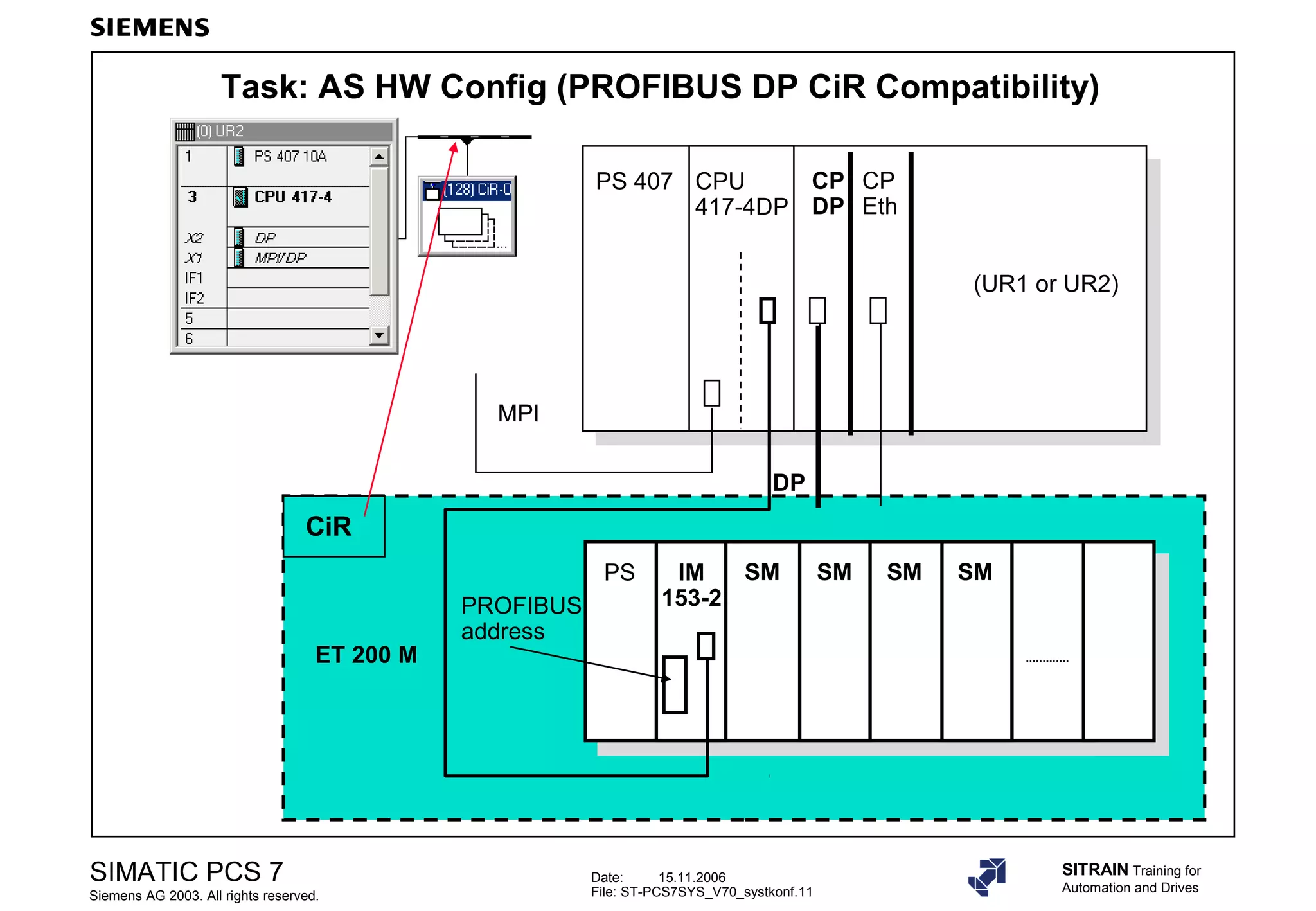
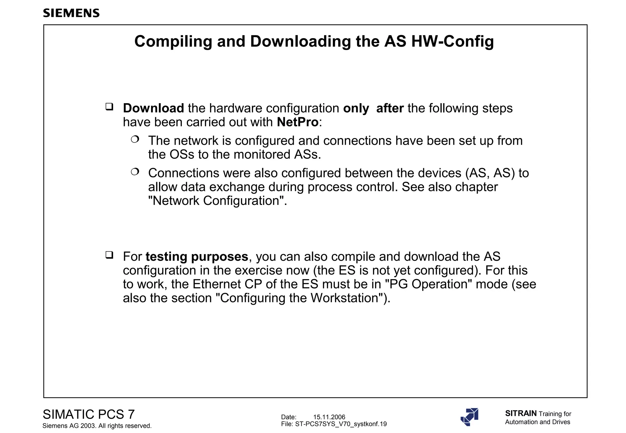
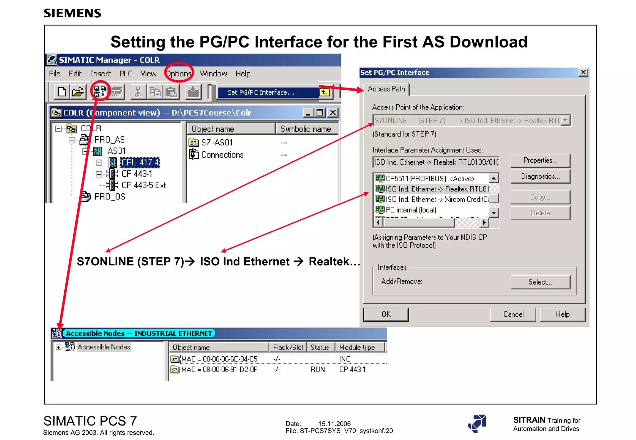
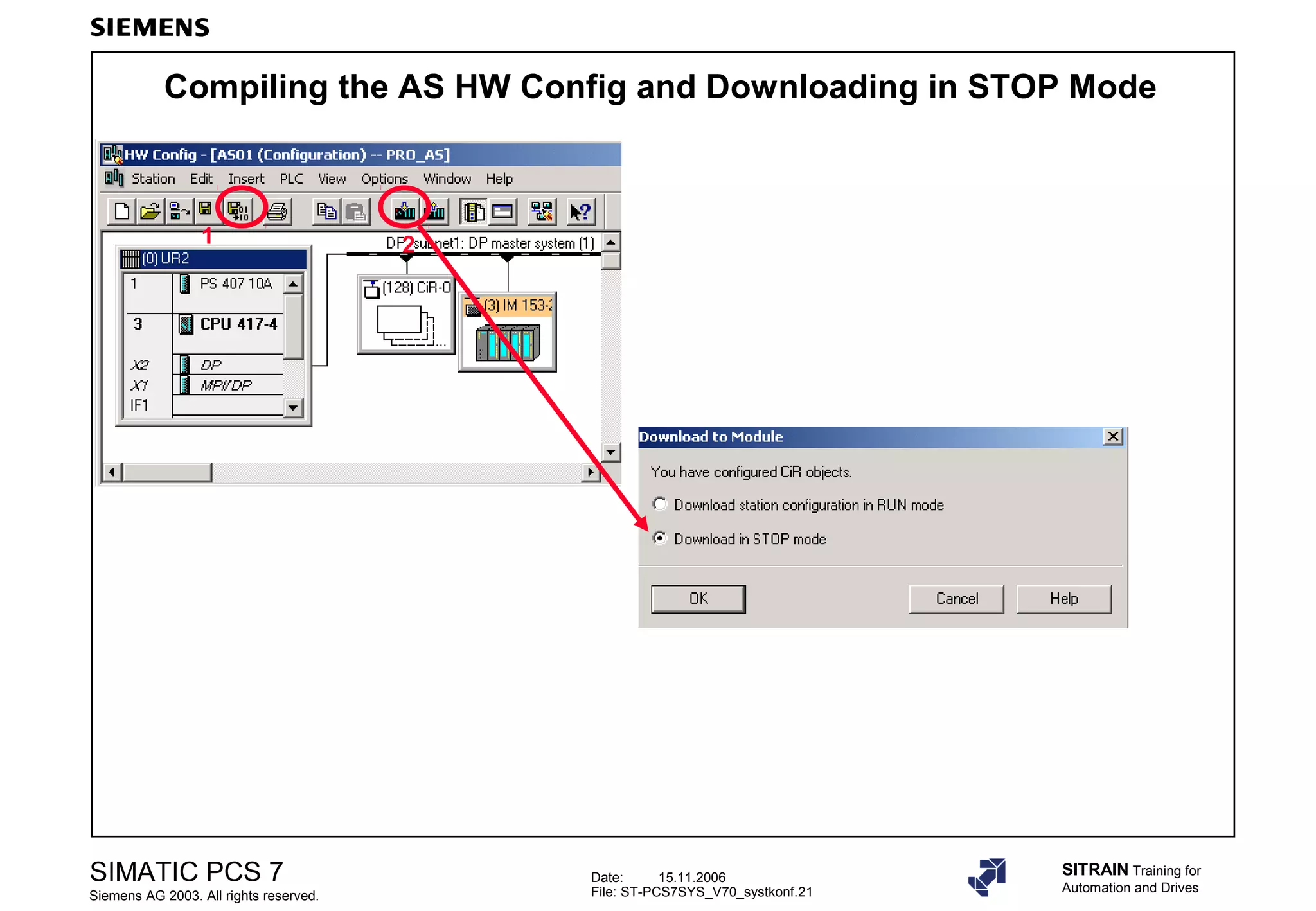
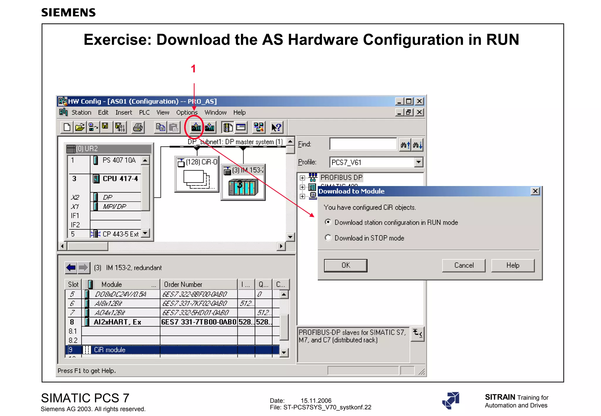
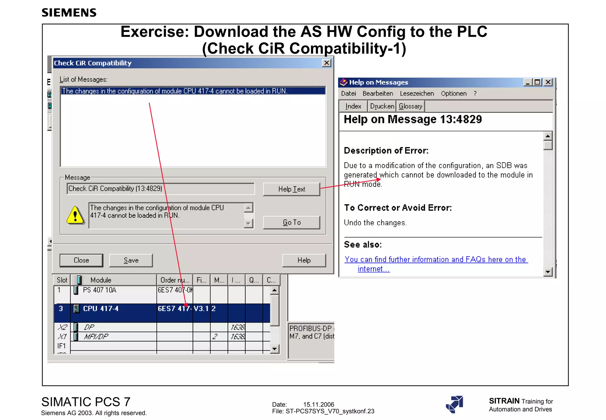
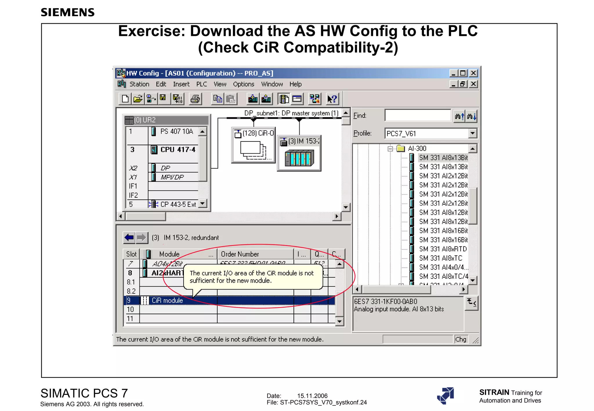
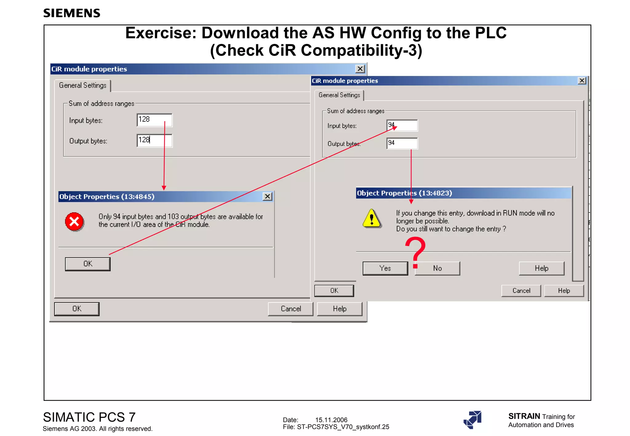
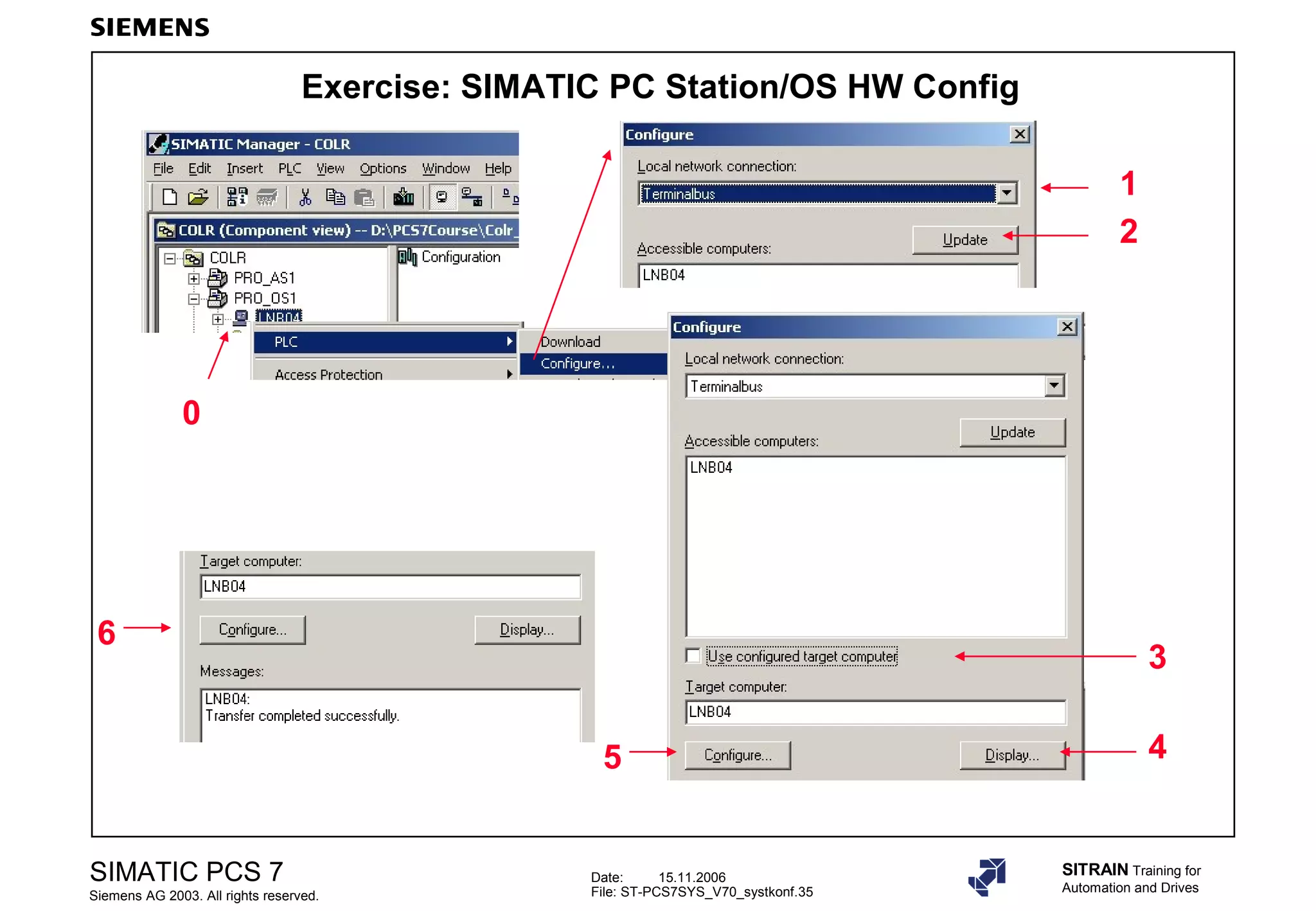
Instructions on compiling, downloading configurations for AS HW and checking compatibility through exercises.
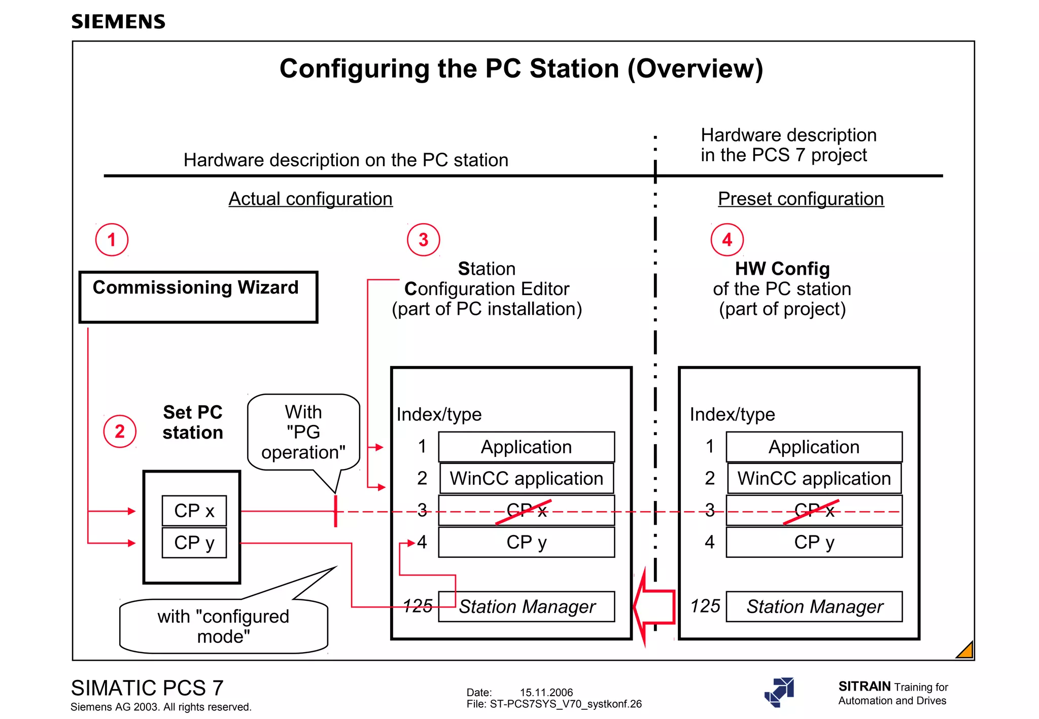
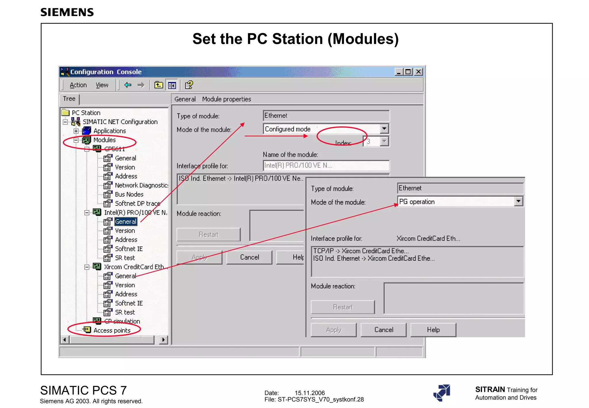
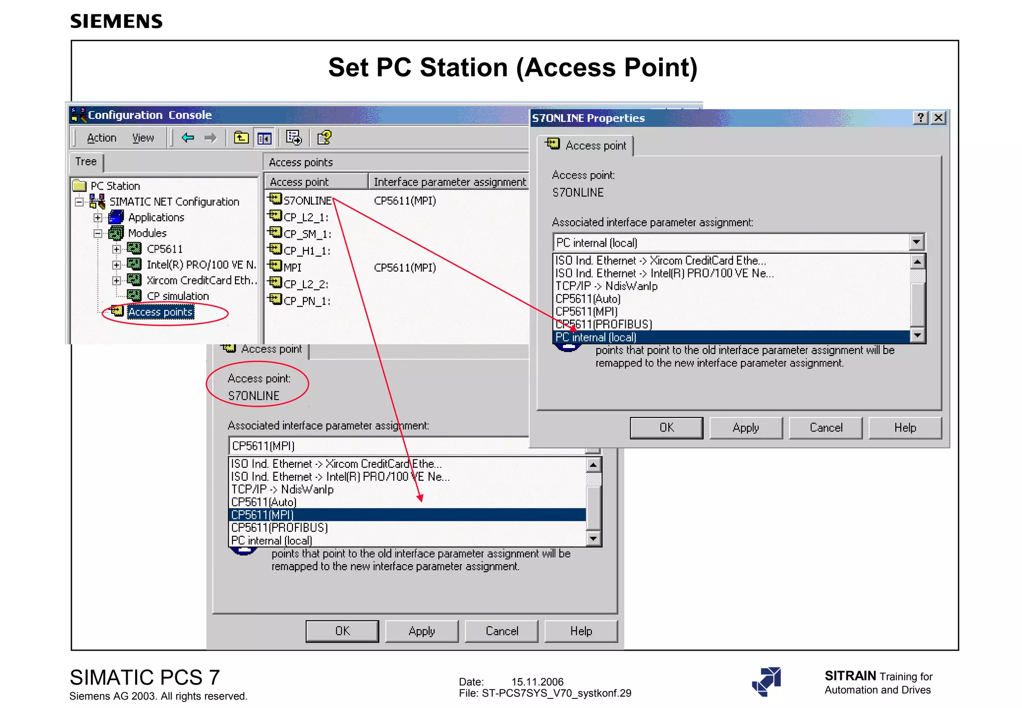
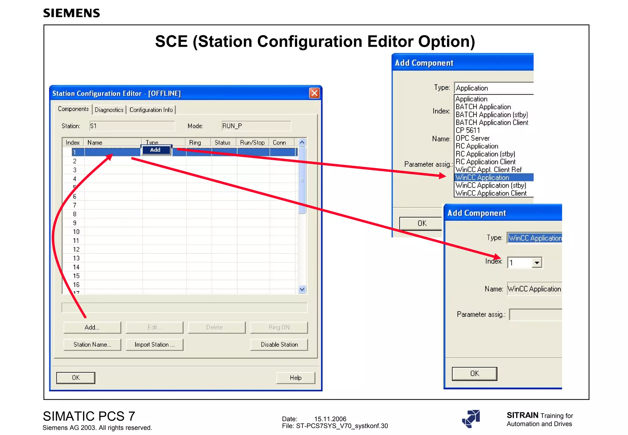
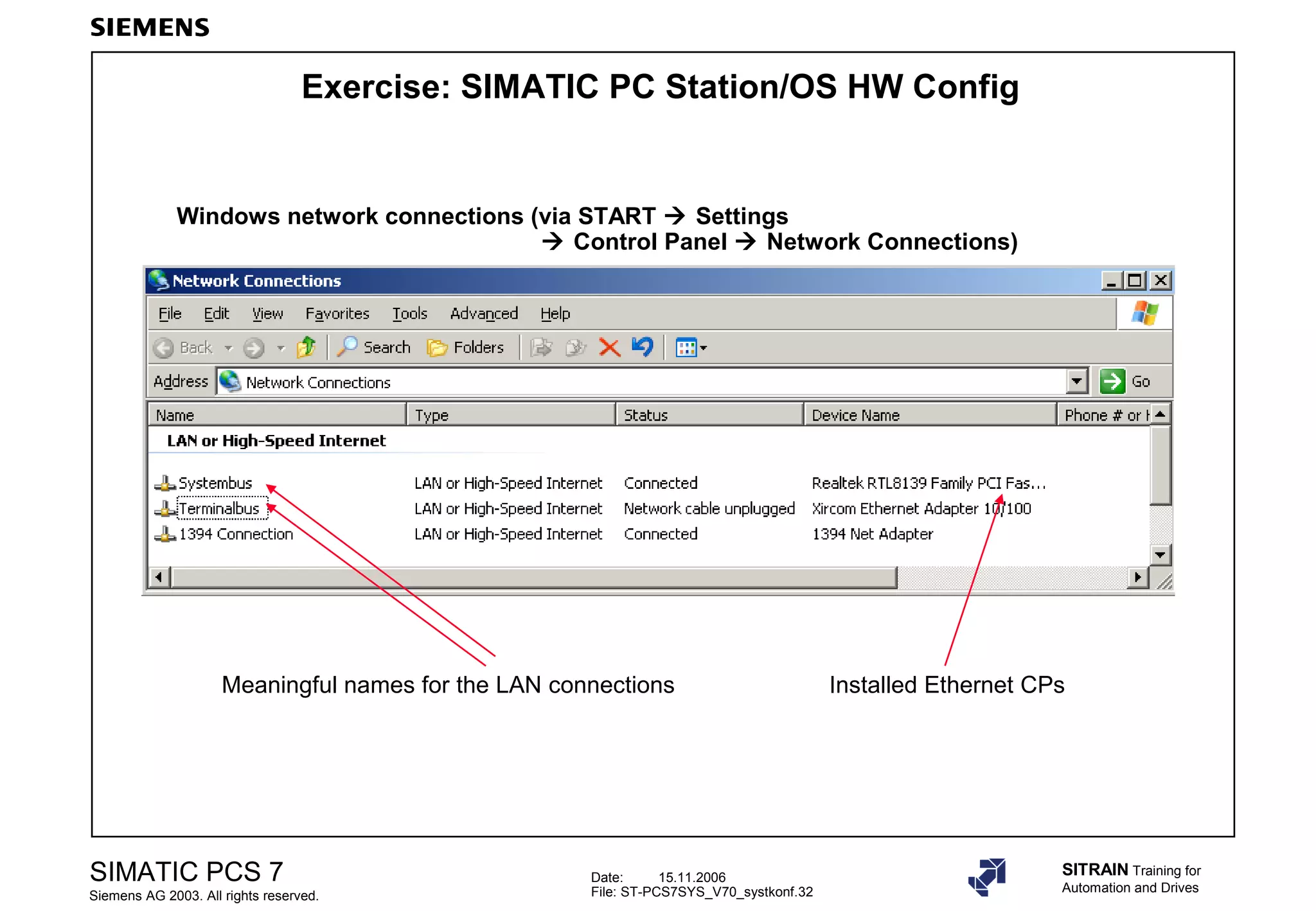
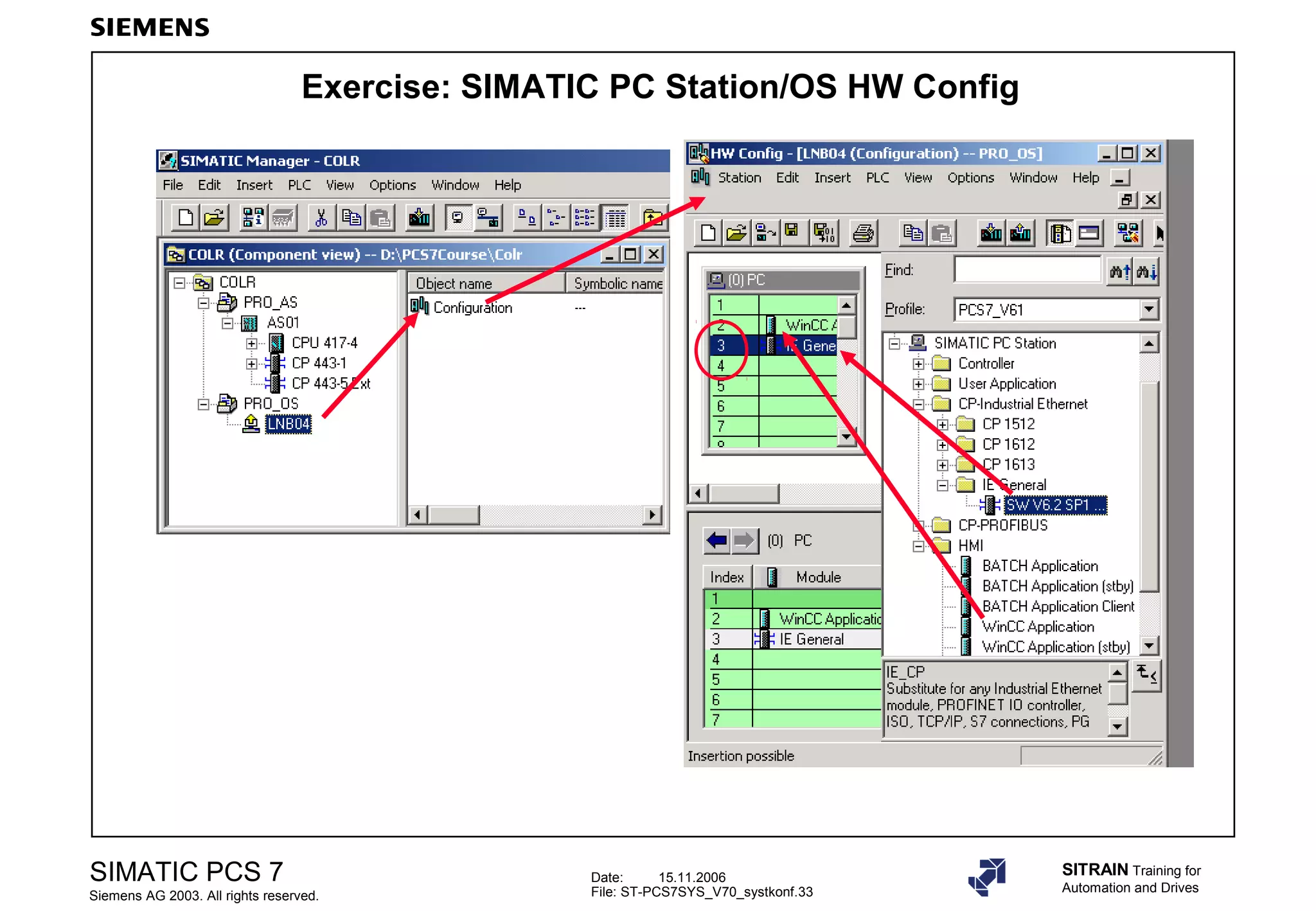
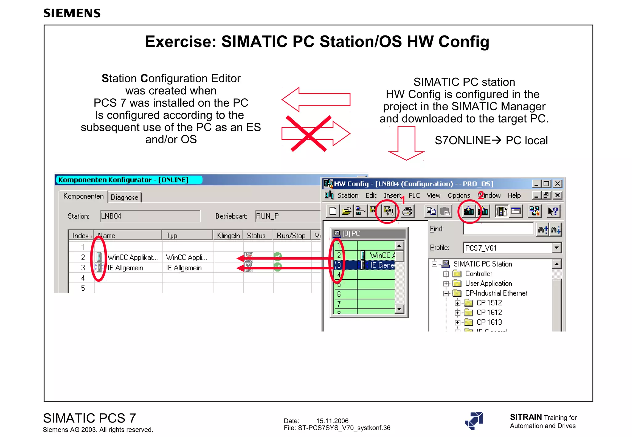
Process of configuring PC stations, including hardware descriptions and setup using the Station Configuration Editor.
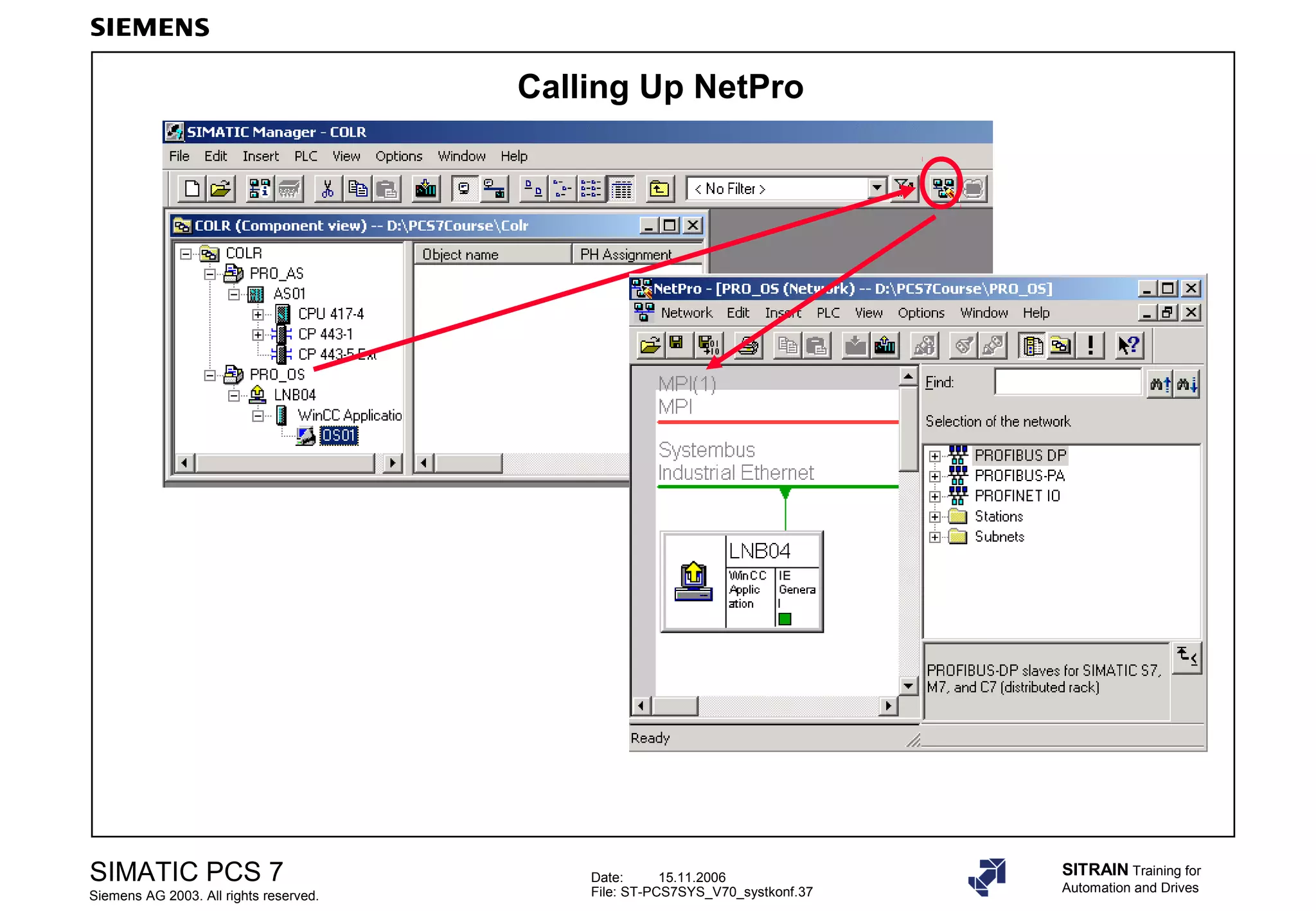
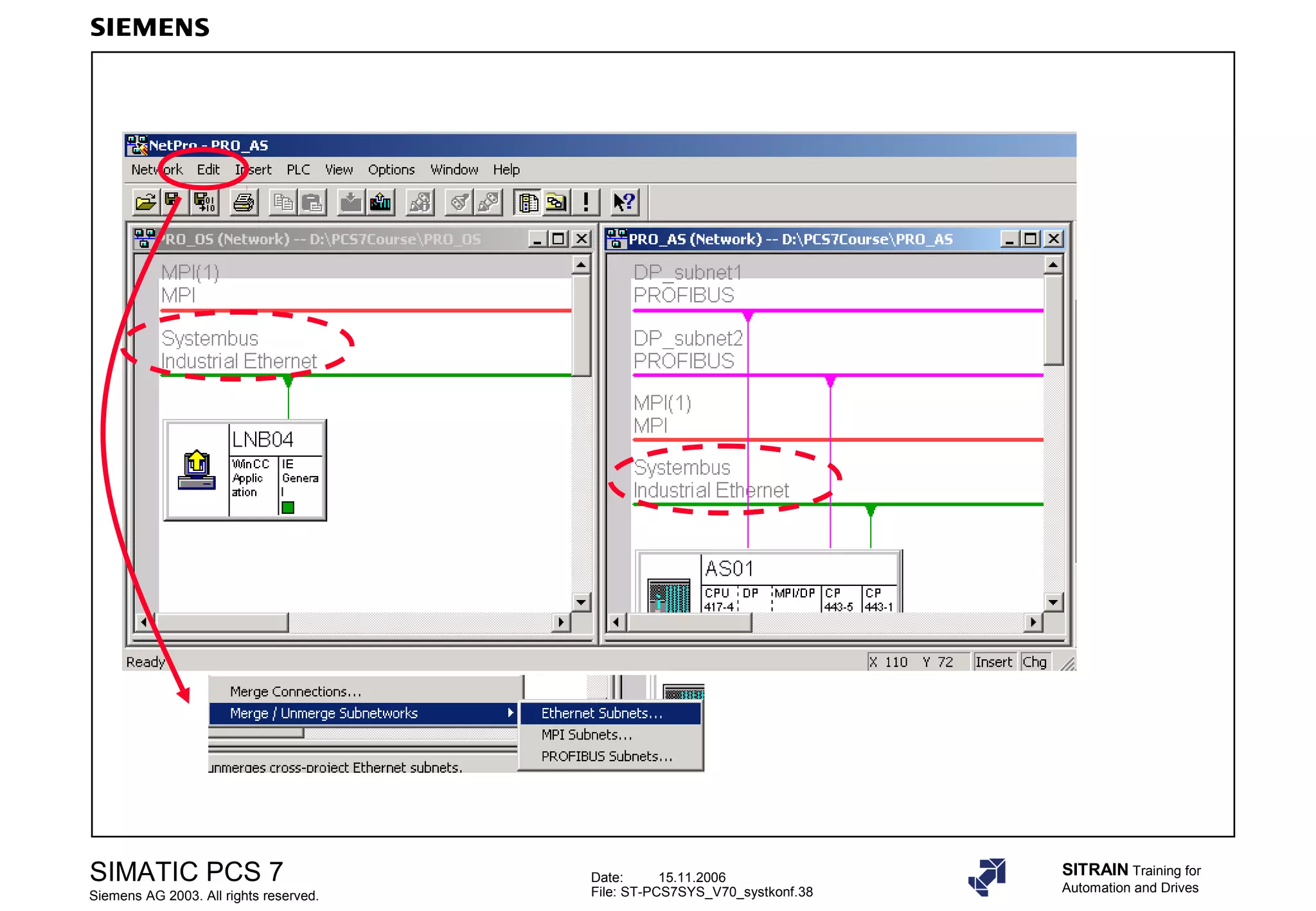
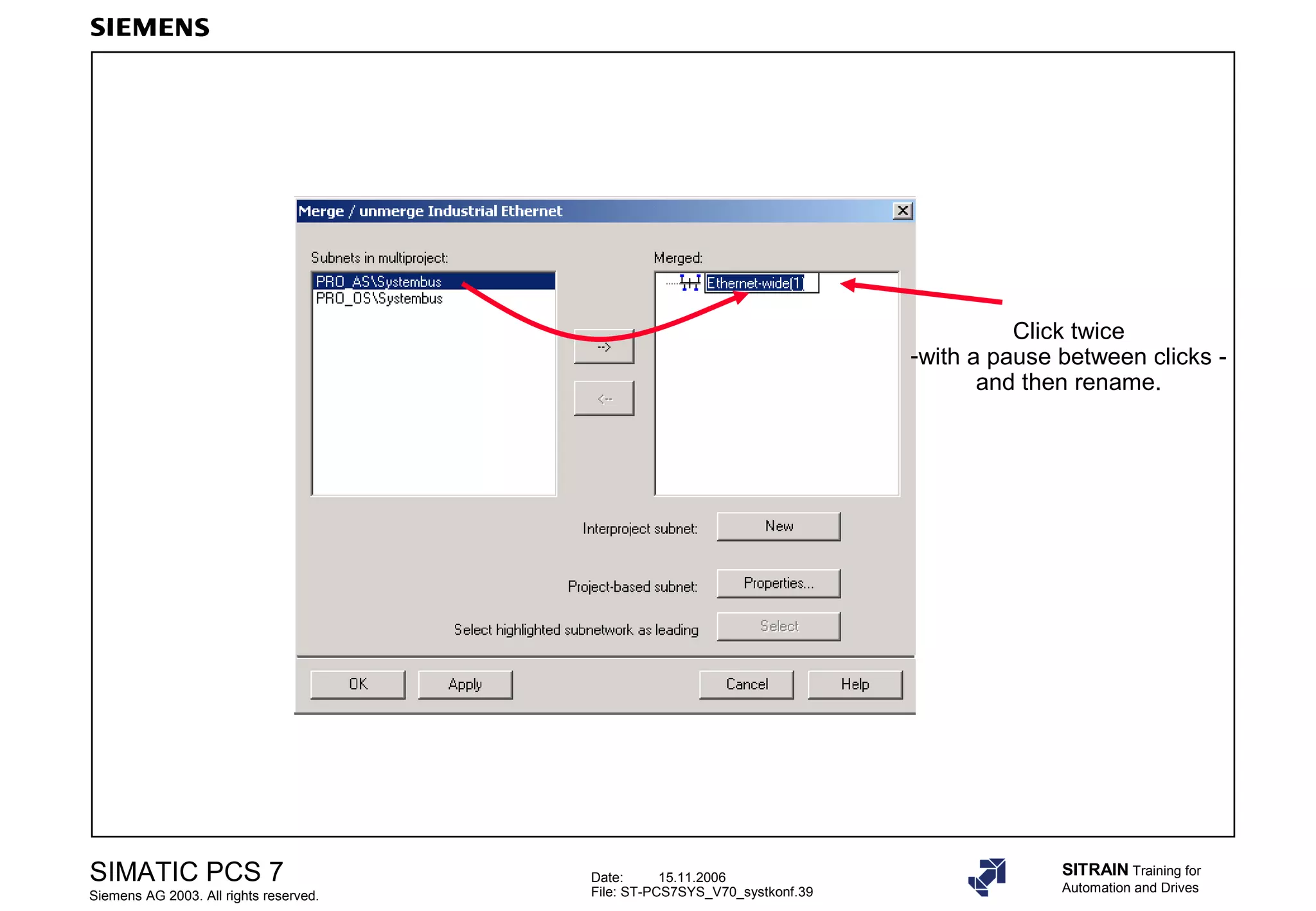
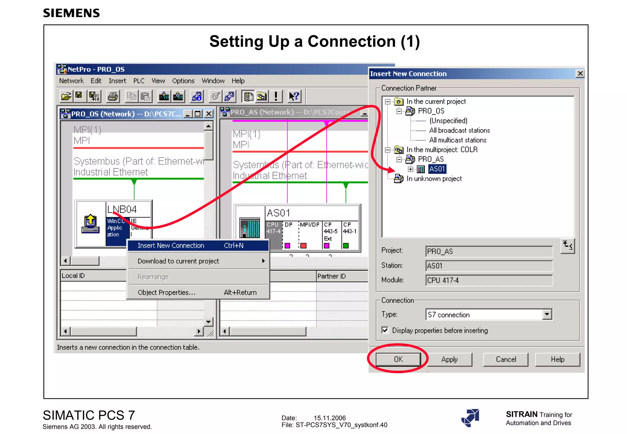
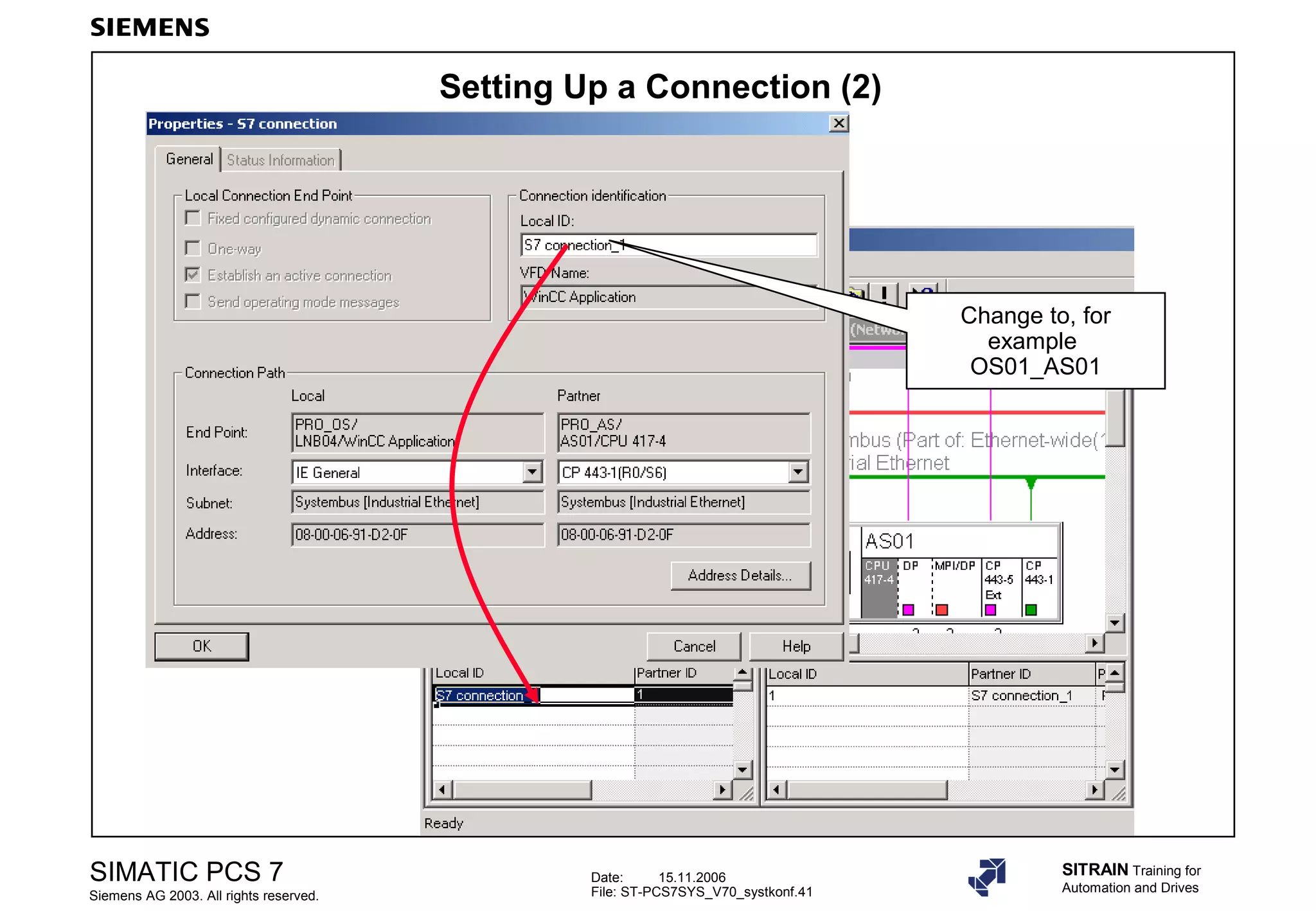
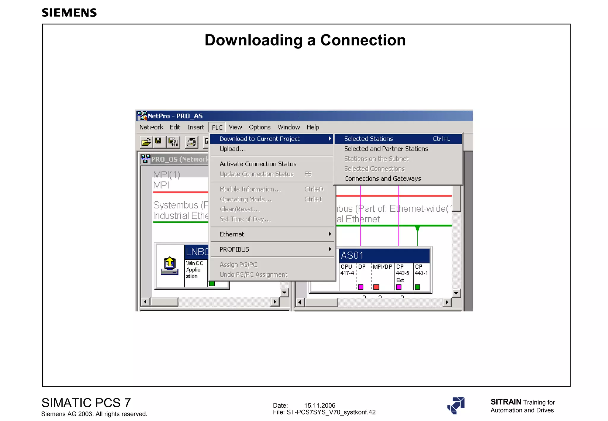
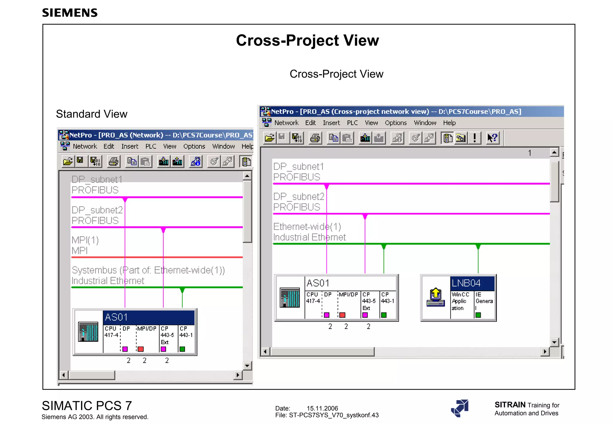
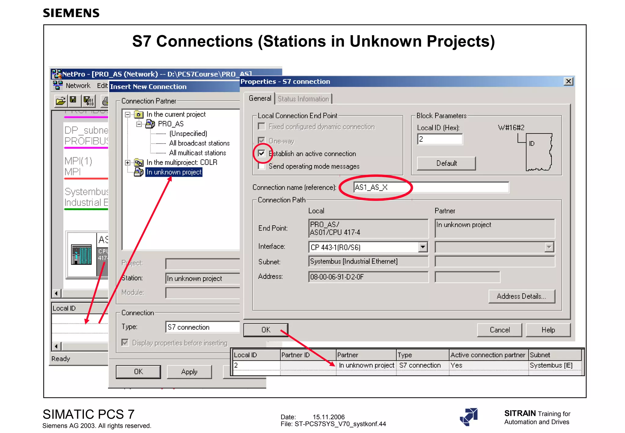
Guidelines for managing network connections, setting up communication, and visualizing connections across projects.


![E20001 a239-p280-x-7600[1]](https://cdn.slidesharecdn.com/ss_thumbnails/e20001-a239-p280-x-76001-140908052339-phpapp01-thumbnail.jpg?width=640&height=640&fit=bounds)


![Vibe Coding vs. Spec-Driven Development [Free Meetup]](https://cdn.slidesharecdn.com/ss_thumbnails/vibecodingvsspecdrivendevelopment-251209105622-43f455e7-thumbnail.jpg?width=640&height=640&fit=bounds)


