Downloaded 29 times


![Picture Tree Manager
PCS 7 WinCC Basic Process Control 4-37
C79000-G7076-C777-02
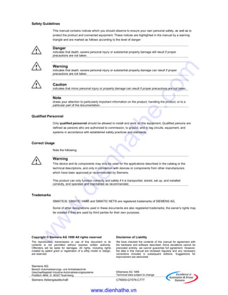
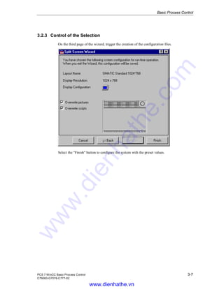
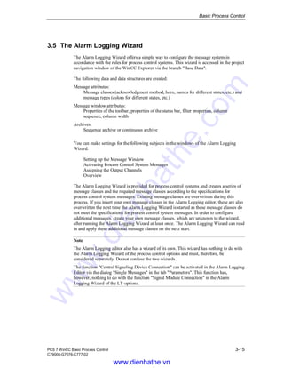
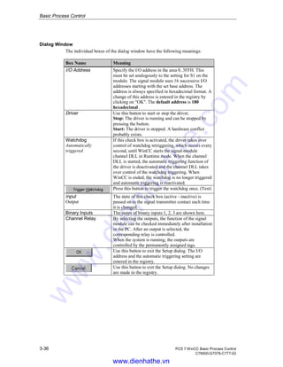
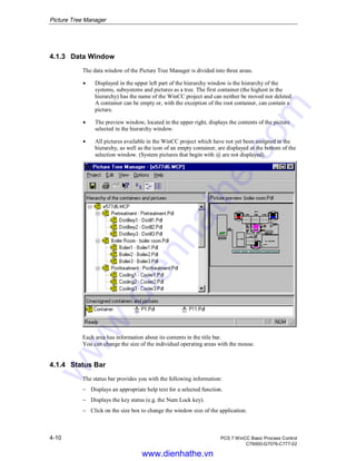
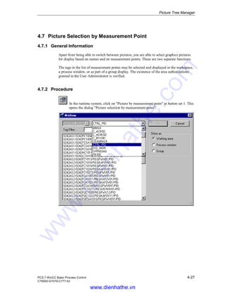
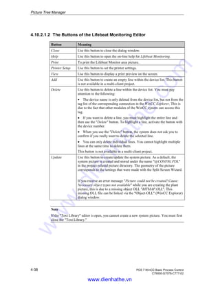
4.10.2.1.1 The Device List of the Lifebeat Monitoring Editor
General Information about the Device List
Lifebeat Monitoring is configured by means of the device list. Each device name is stored
as a tag within the WinCC Explorer. The tag name has the following structure:
"@<Devicename>." If this tag exists already, its parameters are changed. For Lifebeat
Monitoring, the data type of the tags is of secondary significance as the status of the tags is
the only thing that is scanned.
Note
It is sufficient for Lifebeat Monitoring to set a device name in the device list for every
connection to be monitored.
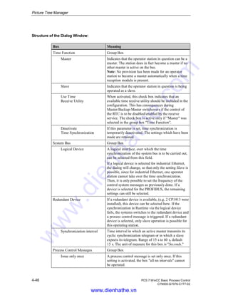
Structure of the Device List Table
Area Name Meaning
Device Name Enter a unique device name in this box. The name can have a
maximum of 15 characters. The following naming conventions exist
for assigning device names:
• No key words (according to C conventions), e.g.: float, type, main,
void
• No special characters or coupling characters ( @ + - / & ’" [ ] * { } .
: < > ; = )
• No spaces
The device names are predefined in a multi-client project.
Device Type Use this box to set the device type. Double click on the box to open a
selection box. The following device types are available:
OS-OP Operator Panel
OS-PC Office PC
OS Industry PC
PLC-4xx S7-4xx
PLC-3xx S7-3xx
PLC-2xx S7-2xx
MC
S7-EDC
The device type is predefined in a multi-client project.
Connection Double click on the box to open a selection box. Select one of the
available configured connections in this box.
www.dienhathe.vn
www.dienhathe.com](https://image.slidesharecdn.com/siemenswinccmanual-pcs7winccbasicprocesscontrol-180727015733/85/Siemens-win-cc-manual-pcs-7-wincc-basic-process-control-99-320.jpg)


![Storage
5-18 PCS 7 WinCC Basic Process Control
C79000-G7076-C777-02
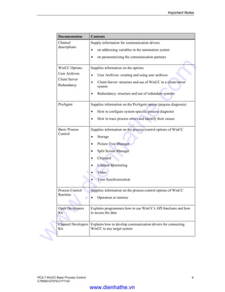
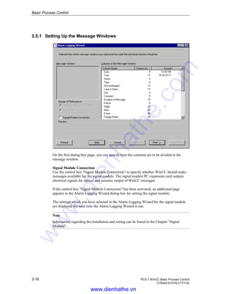
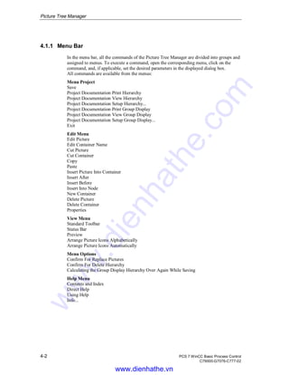
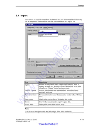
5.7 The Configuration File "ARCHIV.CFG"
The Folder "ARCHIV"
When a new WinCC project is created, the folder "ARCHIV" is created in the project
folder. The folder "ARCHIV" is also automatically created when projects originally created
in older versions of WinCC are opened for the first time.
The Configuration File "ARCHIV.CFG"
The configuration file "ARCHIV.CFG" must be located in the folder "ARCHIV".
"ARCHIV.CFG" allows numerous Storage setting options. "ARCHIV.CFG" can be created
with a text editor. To call up a text editor, you can, for example, activate the menu item
"File - New" in MS-Explorer and select "Text File".
With the "ARCHIV.CFG" file, Storage parameters, which can otherwise only be changed
in the registry, can be set directly from the user interface. Moreover, by linking this file to
the project, all customer-specific settings are transferred to each computer onto which the
project is imported.
When Runtime is started, the entries in the registry and the ARCHIV.CFG file are checked
in parallel. The ARCHIV.CFG file has higher priority here and determines the values
accepted from the archive server.
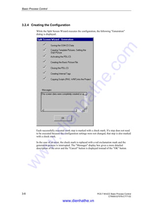
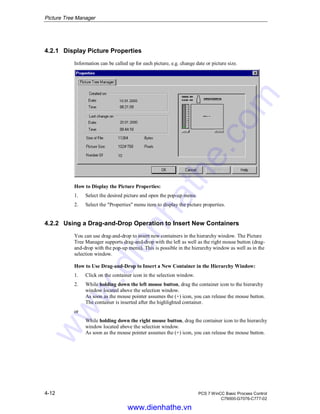
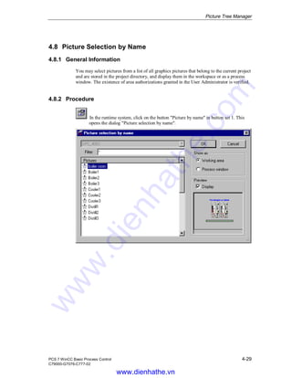
Structure of the Configuration File "ARCHIV.CFG"
The configuration file "ARCHIV.CFG" must begin with the expression "[Archiv-RT]".
Each line contains a keyword, followed by an equal sign and a numerical value (decimal
number). The equal sign is preceded and followed by a blank space. A typical configuration
file follows:
Typical Configuration File "ARCHIV.CFG"
[Archiv-RT]
CalculateRequiredSizeForExport = 1
SplitJobInterval = 180
WaitBetweenSplitJobIntervals = 250
WaitBeforeStartup = 500
If entries are missing in "ARCHIV.CFG" or if "ARCHIV.CFG" is missing completely,
WinCC falls back on internal settings with useful values. In case of doubt, entries in
"ARCHIV.CFG" should, therefore, be omitted.
Note:
All numerical entries must always be in decimal format. Negative numbers are permitted.
www.dienhathe.vn
www.dienhathe.com](https://image.slidesharecdn.com/siemenswinccmanual-pcs7winccbasicprocesscontrol-180727015733/85/Siemens-win-cc-manual-pcs-7-wincc-basic-process-control-130-320.jpg)


The document is the WinCC Basic Process Control Manual, describing the setup, functionality, and components of the WinCC system, particularly for version 5. It covers essential topics such as process control options, system configuration, and the role of different editors within the environment. Additionally, it includes safety guidelines, technical support information, and references to other relevant documentation.


![Attack surfaces and attack tress[inform]](https://cdn.slidesharecdn.com/ss_thumbnails/lecture03-260108015941-a4dee53b-thumbnail.jpg?width=640&height=640&fit=bounds)


