Download to read offline
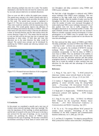
![Before moving into the design and implementation of
topology and comparisons between CSMA/CA and TDMA,
let us discuss about existing mechanisms used in a typical
protocolfor wireless sensor network.
The protocols for WSN can either be contention based (non-
schedule based) or contention free (schedule based). Certain
protocols are hybrid protocols that use both contention based
and contention free methods at various stages of traffic flow.
Contention based protocols are generally based on CSMA
(Carrier Sense Multiple Access). They need to sense the
channel and ensure it is available before transmitting. One of
the main advantages of the contention based protocol is that
the nodes need not be time synchronised with each other.
Whenever a node needs to send a message, it sends an RTS
(request to send) and sends the message upon receiving a
CTS (clear to send). Contention based protocols are
generally considered suitable when there is low traffic.
During high traffic conditions there can be an increase in
collisions and overhead, which results in more energy
consumption and delay. Contention free protocols are
generally TDMA (Time Division Multiple Access) based.
Each node uses a fixed time slot to transmit their data. Time
synchronisation among nodes is needed. They are suitable
for reasonable amount of traffic, ideally in a periodic sensing
environment. Network scalability here is difficult.
The reason for the preference of TDMA over CSMA in the
implementation of the protocol is that, we are concerned
with a special topology of sensor nodes: a chain type
topology also the number of nodes are considerable high.
The application favours a periodic and predictable traffic.
Therefore TDMA becomes automatic choice of preference
since TDMA performance better with the following
scenarios [1].
1. When thetopology is large and relatively stable.
2. Traffic is comparatively high (as the topology is
large the traffic is considered to be high).
3. A periodic data flow.
One of the main issues with wireless sensor networks is
energy consumption by the sensor nodes while transmitting
messages. All the sensor nodes are battery operated. Due to
this fact any protocol involving the sensor nodes has to be
energy efficient. The medium access control (MAC) layer is
one area where energy efficiency can be achieved by
implementing energy saving protocols. The new MAC
protocol aims to deliver the energy efficiency by making the
sensor nodes to sleep as much as possible without affecting
the normal operation for which the sensor network is
intended for. One other reason why we are attracted to
TDMA technique is that it provides more opportunities to
achieve energy efficiency than CSMA.
2. Literature Review
There are some early works on the development of protocol
for chain type topology, PEGASIS [2] (Power Efficient Data
Gathering in Sensor Information Systems) is one such
approach. In this approach, each node would forward its data
along the chain to a particular node (Leader Node) which
communicates directly to the sink. The data are fused from
one node to another therefore the data size is same for each
node this helps in equal consumption of energy by each node.
The Leader Node is then switched to other nodes in turns to
equally distribute energy.
One of the earliest works in energy efficient MAC protocol
for multi-hop protocol is the PAMAS [3] (power aware
medium access with signalling). In this protocol separate
channels for control and data was used. The node senses the
channel with the control channel if it discovers that a
neighbouring node is transmitting it goes to sleep if not data
is transmitted using the data channel. Since the data and
control channels are different there is no collision between
data and control signal. This protocol is well suited for low
load conditions. One of the major drawbacks of PAMAS is
that it requires two separate radios for data and control
channel which makes the hardware expensive and moreover
it is difficult to implement practically.
One of the protocols that is closely related to ours is LC-
MAC [4] or the Long Chain MAC. As the name suggests this
protocol is designed for a chain type topology. In this
protocol the end node sends the LDP (Location Detect
Package), adding its address, to the neighbouring node. Upon
receiving this message, the neighbouring node will add its
address and sends to its neighbour. This continues until the
packet receives the sink. The sink, then transmits the packet
back along the path, thus all nodes will gather all location
information.
After location identification a staggered wakeup schedule
(SWS) is created. During the message relay all nodes follow
the SWS and the messaged is relayed to the sink. It is to be
noted that there are no RTS and CTS message exchange as
the nodes follow an agreed schedule so there is no possibility
of a collision. A super sync message SSYNC is passed prior
to actual data exchange. This SSYNC message contains the
information when and how much each node would transmit.
This is done similar to the LDP message each node would
update when and how much it would transmit in the SSYNC
and passes until the message receives the sink. The authors
show that LC-MAC performs considerably better in terms of
latency, throughput and energy than S-MAC (discussed in
the following section).
There are several energy efficient protocols developed for
wireless sensor networks. One of the most early and
significant protocols is the S-MAC [5] which is contention
based. For the first time, a listen and sleep mode was
introduced. In listen mode the node operates normally. In
sleep mode the node switches off its radio, saving power.
The duration of sleep and listen is fixed for all nodes.
Neighbouring nodes with the same sleep and listen schedule
formed a virtual cluster. The data was sent with RTS and
CTS messages to avoid collision (since it is contention
based).](https://image.slidesharecdn.com/46023606-520a-4fd7-bb5b-d91356aeca75-161204000343/85/ShortPaper-2-320.jpg)
![T-MAC[6] and DS-MAC[7] are improved versions of S-
MAC. T-MAC makes use of different listen/sleep duration
depending upon the traffic conditions. DS-MAC changes the
duty cycle according to the traffic.
B-MAC[8] is another contention based protocol where the
nodes chose their own sleep duration. They wake to sense
the channel for any data destined to them. If there is no data
for them they go back to sleep. When a node needs to send a
message it first sends a preamble which contains the address
of the destination node. The destination node wakes up and
senses the channel; it would sense the preamble and stay
awake to receive the data. Although this protocol was simple
and seemed to save energy, the preamble had to be
transmitted for a long time for the destination node to sense
it. Long preamble consumed more energy. This short coming
was solved by Wise-MAC[9], which made the nodes
remember its neighbours sampling offsets. By knowing the
sampling offsets the start time of the preamble is adjusted to
match the wake up time of the destination node, thereby
reducing the length of thepreamble.
Z-MAC[10] is a hybrid protocol which operates in both
contention based and contention free mode. A node uses the
time slot allocated for it to transfer data. It can also use other
node’s slots to transfer data if it is free. Generally all nodes
use back-offs before sending their data. If the node is
sending in its own time slot then it uses less number of back-
offs than other nodes which are contending for the same time
slot, thereby the slot owner gets priority. This protocol
makes use of the best of both contention based and
contention free modes. Another hybrid protocol is the µ-
MAC[11]. It has a contention period where the nodes send
data in their respective time slots and a contention free
period in which the nodes compete for a time slot. This
protocolis a high level protocoland is application specific.
DEE-MAC[12] is a TDMA based protocol. In this protocol
time is divided into sessions. Each session have a contention
period and a transmission period. The nodes send request to
the cluster head in the contention period and the cluster head
allocates slots for the nodes in the transmission period. A
node contends only when it has a data to transmit. In this
way unused time slots are eliminated.
3. Methodology
Considering our requirements, we need to test the
performance of CSMA/CA and TDMA in a chain topology.
The CSMA/CA access technique is employed in the Wi-Fi
module of ns-3 while the TDMA module is supported by a
special module developed for ns-3.19 called Simple TDMA
module. We propose to develop and analyse the contention
based and schedule based protocols using the Wi-Fi and
Simple TDMA moduleavailable in ns-3.
3.1 The Wi-Fi module
This module consists of the following components.
1. Phy layer models
2. MAC Low level models
3. MAC High level models
4. Rate control algorithms (Aarf, Arf, Cara, Onoe,
Rraa, ConstantRate, and Minstrel)
The Phy layer model is responsible for the transmission and
reception of data frames. It is guided by the
InterferenceModel/ErrorRateModel to determine the
probability of successful reception of frames. The MAC Low
level model implements the DCF and EDCF with the help of
the DcfManager. This layer determines the duration and
timings of RTS/CTS/ACK messages. The MAC High level
model takes care of beacon generation, probing and associate
state machines. The Rate control algorithms are used by the
MAC Low level models. Figure gives the detailed working
structureof the Wi-Fi Module.
3.2 The TDMA module
The TDMA module is much simpler than the Wi-Fi module.
TDMA module for ns-3 is not officially released but it has
been extensively tested before being proposed. This module
uses a Simple Wireless Channel which takes only the
transmission distance as the only criteria.
The total channel bandwidth available for the nodes is
equally divided among the participating nodes. Each node is
allotted with dedicated time slots, usually of fixed lengths.
The nodes transmit their packets only in their allotted time
slots. Each transmission slot is separated by a guard interval.
This is to ensure that the data transmission in one slot does
not interfere with the neighbouring slot. Generally the guard
time is the time taken for a data packet to travel the specified
transmission distance. It is specified by the Simple Wireless
channel used in the model. This module assumes that the
nodes are synchronised with each other. Figure 3-1 shows the
default time slot allocation in TDMA module.
Figure 3-1: TDMA Default Time Slot Allocation
4. Results
4.1 Throughput Analysis
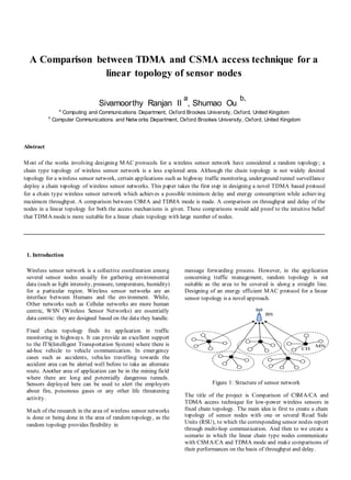
We create the chain topology of nodes as explained
previously. We employ TDMA and CSMA access
technology and calculate the average throughput achieved by
both the techniques. The various parameters for the
simulation are given in Table 4-1 below. It is to be noted that
the transmission distance is chosen to be a large value so that
all nodes are able to reach the Sink in one hop. We compare
the throughput of TDMA and CSMA in three scenarios of 5,
10, 50 nodes.](https://image.slidesharecdn.com/46023606-520a-4fd7-bb5b-d91356aeca75-161204000343/85/ShortPaper-3-320.jpg)


This document compares the TDMA and CSMA access techniques for a linear topology of sensor nodes. It first provides background on wireless sensor networks and discusses applications that use a fixed chain topology. It then explains that TDMA is generally more suitable than CSMA for a linear chain topology with a large number of nodes, periodic traffic, and relatively high traffic. The document reviews several existing MAC protocols designed for chain topologies and discusses their advantages and disadvantages. It focuses on comparing the throughput and delay of nodes in a linear topology using TDMA versus CSMA.