Downloaded 243 times
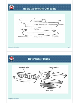
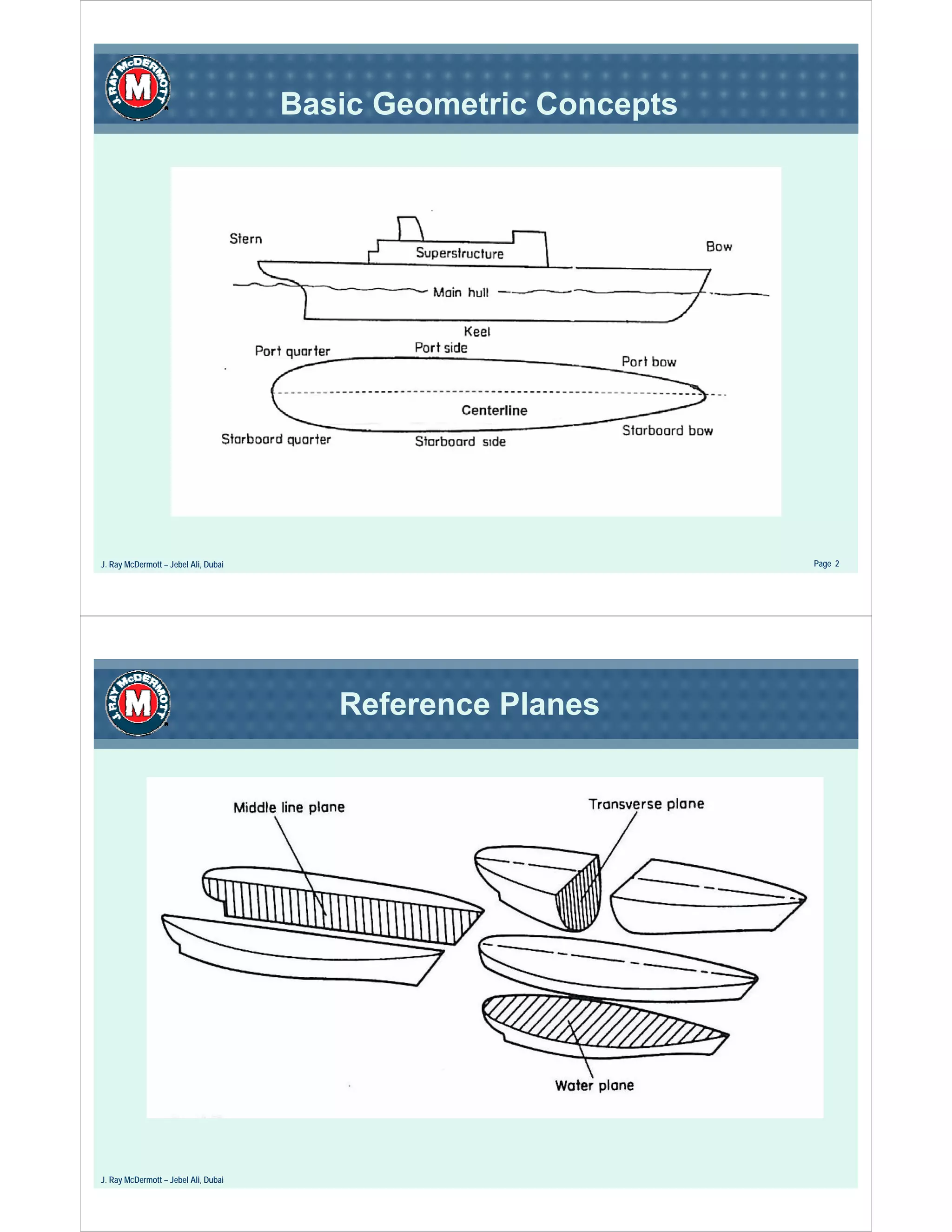

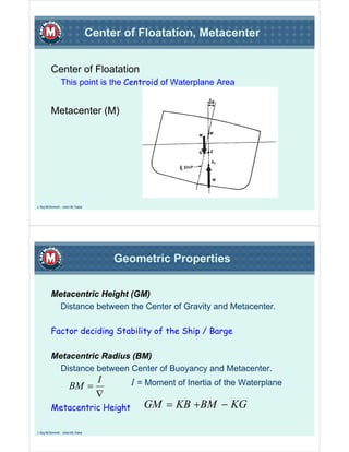

This document discusses basic geometric concepts and properties related to ship design and stability. It defines key reference planes and dimensions used in ship plans. Reference planes include the waterline, centerline, and perpendiculars. Dimensions include length, breadth, draft, depth and volume. Ship motions such as surge, sway, heave, roll, pitch and yaw are also defined. The document then discusses coefficients of form, displacement, weight, buoyancy, centers of gravity/buoyancy/floatation, metacenters, and how these factors influence a ship's stability. Free surface effect on partially-filled tanks is also mentioned.


