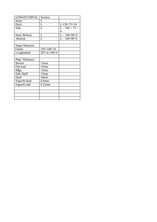
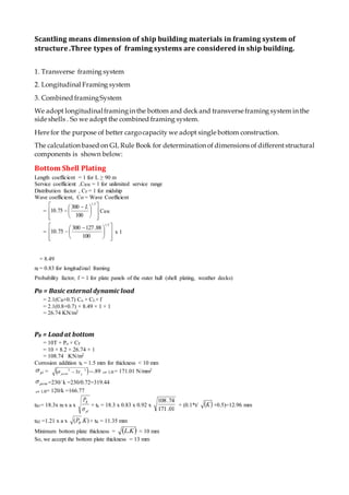
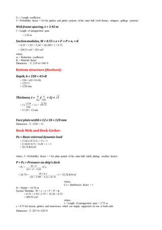
The document discusses the scantling, or dimensions, of structural components for a ship building project. It outlines three common framing systems - transverse, longitudinal and combined - and notes this ship will use a combined system with longitudinal framing on the bottom and deck and transverse framing on the side shells. Dimensions are then calculated based on governing rules for various structures like the bottom shell plating, side plates, bilge, keel, web frames, stringers, longitudinals and deck beams. A summary table is also included listing the structural components, their sections and plate thicknesses.
A Presentation on the basic Structural members of a Ship Hull.Prepared for Training related activities.
Prepared by:Vipin Devaraj,
38Th RS,
Dept Of Ship Technology,
Cusat,INDIA
contact:vipindevaraj94@gmail.com
+919995568268
Dublin Port Company required a twin-screw work barge/pontoon to be built for Harbor and
Coastal work including the Irish Sea. The vessel which we design complies with Bureau
Veritas requirements for workboats. Its duties include bed leveling, towing, buoy and quay
maintenance and an oil recovery option with ½ day „bolt on‟ facility. We can also count
diving support, anchor handling, supply, survey, mooring, pollution control, etc. for its duties.
Requested main specifications are:
L.O.A. 20 meters approx.
Beam O.A. 8 meters approx.
Depth midships. 2.7 meters approx.
Displacement 170-ton approx.
Leveling depth 16 meters approx
Fuel oil capacity 25,000 liters approx.
F.W. capacity 10,000 liters approx.
The hull, propeller, shaft, main and auxiliary engines, rudder and steering gear are selected by
taking into account Classification Society regulations. All trade names mentioned in the
specifications describe the desired quality of equipment and not intended to exclude other
makes of similar quality.
My original presentation was made in Japanese but I've translated the slide to English. FEA in ship design process is a bit different from other industries. I've summarized current situation about FEA and 3D-based-design in our industry.
Roof Truss Design (By Hamza Waheed UET Lahore )Hamza Waheed
This presentation defines, describes and presents the most effective and easy way to design a roof truss with all the necessary steps and calculations based on Allowable Stress Design. Soft-wares like MD Solids, Truss Analysis have been used. It is most convenient way to design a roof truss which is being the most important structural components of All types of steel bridges.
Content;
1. Top spherical dome.
2. Top ring beam.
3. Cylindrical wall.
4. Bottom ring beam.
5. Conical dome.
6. Circular ring beam.
The basics of enticing water tank design and the related components are broadly calculated in this document. The next few documents will demonstrate the design of Intze tank members like column, bracing and foundation. Keep following the updates.....
Hello everyone! I am thrilled to present my latest portfolio on LinkedIn, marking the culmination of my architectural journey thus far. Over the span of five years, I've been fortunate to acquire a wealth of knowledge under the guidance of esteemed professors and industry mentors. From rigorous academic pursuits to practical engagements, each experience has contributed to my growth and refinement as an architecture student. This portfolio not only showcases my projects but also underscores my attention to detail and to innovative architecture as a profession.
Book Formatting: Quality Control Checks for DesignersConfidence Ago
This presentation was made to help designers who work in publishing houses or format books for printing ensure quality.
Quality control is vital to every industry. This is why every department in a company need create a method they use in ensuring quality. This, perhaps, will not only improve the quality of products and bring errors to the barest minimum, but take it to a near perfect finish.
It is beyond a moot point that a good book will somewhat be judged by its cover, but the content of the book remains king. No matter how beautiful the cover, if the quality of writing or presentation is off, that will be a reason for readers not to come back to the book or recommend it.
So, this presentation points designers to some important things that may be missed by an editor that they could eventually discover and call the attention of the editor.
Expert Accessory Dwelling Unit (ADU) Drafting ServicesResDraft
Whether you’re looking to create a guest house, a rental unit, or a private retreat, our experienced team will design a space that complements your existing home and maximizes your investment. We provide personalized, comprehensive expert accessory dwelling unit (ADU)drafting solutions tailored to your needs, ensuring a seamless process from concept to completion.
White wonder, Work developed by Eva TschoppMansi Shah
White Wonder by Eva Tschopp
A tale about our culture around the use of fertilizers and pesticides visiting small farms around Ahmedabad in Matar and Shilaj.
Between Filth and Fortune- Urban Cattle Foraging Realities by Devi S Nair, An...Mansi Shah
This study examines cattle rearing in urban and rural settings, focusing on milk production and consumption. By exploring a case in Ahmedabad, it highlights the challenges and processes in dairy farming across different environments, emphasising the need for sustainable practices and the essential role of milk in daily consumption.
2. Scantling means dimension of ship building materials in framing system of
structure.Three types of framing systems are considered in ship building.
1. Transverse framing system
2. Longitudinal Framing system
3. Combined framingSystem
We adopt longitudinalframingin the bottom and deck and transverse framing system in the
side shells . So we adopt the combined framing system.
Here for the purpose of better cargocapacity we adopt single bottom construction.
The calculation based on GL Rule Book for determination of dimensions of differentstructural
components is shown below:
Bottom Shell Plating
Length coefficient = 1 for L ≥ 90 m
Service coefficient ,CRW = 1 for unlimited service range
Distribution factor , CF = 1 for midship
Wave coefficient, Co = Wave Coefficient
=
5.1
100
300
75.10
L
CRW
=
5.1
100
88.127300
75.10 x 1
= 8.49
nf = 0.83 for longitudinal framing
Probability factor, f = 1 for plate panels of the outer hull (shell plating, weather decks)
Po = Basic external dynamic load
= 2.1(CB+0.7) Co × CL× f
= 2.1(0.8+0.7) × 8.49 × 1 × 1
= 26.74 KN/m2
PB = Load at bottom
= 10T + Po × CF
= 10 × 8.2 + 26.74 × 1
= 108.74 KN/m2
Corrosion addition tk = 1.5 mm for thickness < 10 mm
pl = 22
3 Lperm --.89 LB = 171.01 N/mm2
perm =230/ k =230/0.72=319.44
LB= 120/k =166.77
tB1= 18.3x nf x a x
pl
BP
+ tk = 18.3 x 0.83 x 0.92 x
01.171
74.108
+ (0.1*t/ K +0.5)=12.96 mm
tB2 =1.21 x a x ).( KPB + tK = 11.35 mm
Minimum bottom plate thickness = KL. ≈ 10 mm
So, we accept the bottom plate thickness = 13 mm
3. Side Plate thickness
Side Plate thickness = T +
2
Co
= 8.2 +
2
49.8
= 12.445 13 mm
Bilge thickness
Bilge thickness = Bottom plate thickness = 13 mm
Flat Keel Plate
The thickness of flat plate keel should not be less than
tFK = tB+2.0
=13.0+2.0
=15 mm
So we take the thickness of our flat plate keel as tFK=15 mm The width of flat plate keel is not to be less than :
B= 800+5L (mm)
=800+5*127.88= 1439.44 mm=1.44 m
Web frame and Side Stringers׃
P=Ps=Load on ship side
= 10(T-Z) +Po × CF (1+
T
Z
)
= 10(8.2-5.995) +26.74×1× (1+
.
2.8
955.5
)
= 68.209 KN/m2
where,
Z = vertical distance of the structure’s load centre above base line [m]
= 0.5(depth- double bottom depth)+ double bottom depth
= 0.5(10.76- 1.23) +1.23 = 5.995 m
T = Draft = 8.2 m
CF = distribution factor=1
Co= WaveCoefficient
=
5.1
100
300
75.10
L
CRW
=
5.1
100
88.127300
75.10 x 1
= 8.49
where,
CRW = service range coefficient
= 1 for unlimited service range
Po = Basic external dynamic load
= 2.1(CB+0.7) Co × CL× f
= 2.1(0.8+0.7) × 8.49 × 1 × 0.6
= 16.05 KN/m2
where,
4. CL = Length coefficient
f = Probability factor = 0.6 for girders and girder systems of the outer hull (web frames, stringers, grillage systems)
Web frame spacing,e = 1.92 m
l = Length of unsupported span
= 2.24 m
Section modulus, W = 0.55 × e × l2 × P × nc × K
= 0.55 × 1.92 × 2.242 × 68.209× 1 × 0.72
= 260.21 cm3 ≈261 cm3
where,
nc = Reduction coefficient
K = Material factor
Dimension ׃ T- 219×6+100×9
Bottom structure (Keelson):
Depth, h = 350 + 45×B
= 350 + (45×19.50)
= 1227.5
≈1230 mm
Thickness, t =
ha
h
(
100
h
+ 1) × K
= 1 (
100
1230
+ 1) × 72.0
= 11.29 ≈ 12 mm
Face platewidth ≈12 x 10 = 120 mm
Dimension׃ T- 1230 × 12
Deck Web and Deck Girder:
Po = Basic external dynamic load
= 2.1(CB+0.7) Co × CL× f
= 2.1(0.8+0.7) × 8.49 × 1 × 1
= 26.74 KN/m2
where, f = Probability factor = 1 for plate panels of the outer hull (shell plating, weather decks)
P = PD = Pressure on ship’s deck
= Po ×
HTZ
T
)10(
20
×CD
= 26.74 ×
76.10)2.8995.510(
2.820
×1 = 52.28 KN/m2
where,
CD = distribution factor = 1
H = Depth = 10.76 m
Section Modulus, W = c × e × l2 × P × K
= 0.75 × 1.92× 2.752 × 52.28 × 0.72
= 409.92 cm3
where,
l = Length of unsupported span = 2.75 m
c = 0.75 for beams, girders and transverses which are simply supported on one or both ends
Dimension׃ T- 287×6+120×9
5. Bottom Longitudinal:
Po = Basic external dynamic load
= 2.1(CB+0.7) Co × CL× f
= 2.1(0.8+0.7) × 8.49 × 1 ×0 .75
= 20.06 KN/m2
f = Probability factor = 0.75 for secondary stiffening members
P = PB = Load at bottom
= 10T + Po × CF
= 10 × 8.2+20.06 × 1
= 102.06 KN/m2
ma = 0.204 ×
l
a
[4– (
l
a
)2] = 0.204 ×
75.2
92.0
[4– (
75.2
92.0
)2] = 0.265 ; a = frame spacing
mk = 1 –(lki+lkj)/10³/l= 1- (0.2+0.2)/10³/2..75= 0.99
m = mk
2 – ma
2 = 0.91
σpr =
K
150
= 208.33
Sectional modulus, W =
pr
3.83
× m × a × l2 × P =
33.208
3.83
× 0.91× 0.92 × 2.752 × 102.06 =258.37≈260 cm3
Dimension׃ L – 160×80×14
Side Longitudinal:
Ps = Load on side
= 10(T-Z) + Po × CF (1 +
T
Z
)
= 10(8.2-5.995) + 16.05 x 1 x (1 +
2.8
995.5
)
= 49.83 KN/m2
Section Modulus, W =
pr
3.83 × m × a × l2 × Ps =
33.208
3.83
×0 .91×0.92×2.242 × 49..83
= 83.70 cm3 ≈ 84 cm3
Dimension׃ L – 100 × 75 × 9
Deck Longitudinal:
P = PD = Pressure on ship’s deck
= Po ×
HTZ
T
)10(
20
×CD
= 26.74 ×
76.10)2.8995.510(
2.820
× 1
= 52.28KN/m2
W =
pr
3.83 × m × a × l2 × PD =
33.208
3.83
× 0.91 ×0.92 ×2.752 × 52.28= 132.35≈133 cm3
Dimension =L-130×75×10
Deck Beam:
P = PD = Pressure on ship’s deck
= Po ×
HTZ
T
)10(
20
×CD = 52.28 KN/m2
c = 0.75 for beam & girders
Sectional modulus, Wd = c × a × l2 × K × P = 196.42=197 cm3
6. Dimension׃ L- 160 × 80× 10
Superstructure:
Side plate
1.21*a * √(P.K)+tk
=1.21*.92*√(52.28*.72)+1.5
=6.8+1.5=8.3
Deck Plate
t = (5.5 + 0.02 L ) √k
= 6.837 mm
Scantlings :
WD= C *a * l^2 * k
= 0.75*.92*52.28*2.24^2*0.72
=130 cm^3
Dimension : 180 × 12
Girders
W= C × e × l2 × p × k
=271.97 cm3
Dimension : 220 × 17
Bulkheadplating
t = 6,0√ f
= 6×√0.67= 4.88 mm
f =235/ReH
= 0.67
ReH = minimum nominal upper yield point(N/mm)
Summary Table
WEB FRAME
Items Section
Center Girder T T- 1230 × 12
Side Stringer T T-
219×6+100×9
WEB FRAME T T-
219×6+100×9
Deck Girder T T-
287×6+120×9
Deck Web T T-
287×6+120×9
7. LONGITUDINAL Section
Items L
Deck L L-130×75×10
Side L L – 100 × 75 ×
9
Inner Bottom L L – 160×80×6
Bottom L L – 160×80×6
Super Structure
Girder 150×100×10
Longitudinal 287×6+180×6
Plate Thickness
Botom 13mm
Flat keel 15mm
Bilge 13mm
Side Shell 13mm
Deck 10mm
SuperSt deck 6.8mm
SuperSt side 8.23mm