More than Just Lines on a Map: Best Practices for U.S Bike Routes
Lines Plane 2. ship dimension and length
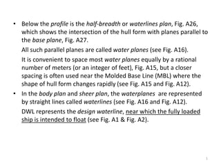
1. • Below the profile is the half-breadth or waterlines plan, Fig. A26,
which shows the intersection of the hull form with planes parallel to
the base plane, Fig. A27.
• All such parallel planes are called water planes (see Fig. A16).
• It is convenient to space most water planes equally by a rational
number of meters (or an integer of feet), Fig. A15, but a closer
spacing is often used near the Molded Base Line (MBL) where the
shape of hull form changes rapidly (see Fig. A15 and Fig. A12).
• In the body plan and sheer plan, the waterplanes are represented
by straight lines called waterlines (see Fig. A16 and Fig. A12).
• DWL represents the design waterline, near which the fully loaded
ship is intended to float (see Fig. A1 & Fig. A2).
1
5. • Below the profile is the half-breadth or waterlines plan, Fig. A26,
which shows the intersection of the hull form with planes parallel to
the base plane, Fig. A27.
• All such parallel planes are called water planes (see Fig. A16).
• It is convenient to space most water planes equally by a rational
number of meters (or an integer of feet), Fig. A15, but a closer
spacing is often used near the Molded Base Line (MBL) where the
shape of hull form changes rapidly (see Fig. A15 and Fig. A12).
• In the body plan and sheer plan, the waterplanes are represented
by straight lines called waterlines (see Fig. A16 and Fig. A12).
• DWL represents the design waterline, near which the fully loaded
ship is intended to float (see Fig. A1 & Fig. A2).
5
6. • Below the profile is the half-breadth or waterlines plan, Fig. A26,
which shows the intersection of the hull form with planes parallel to
the base plane, Fig. A27.
• All such parallel planes are called water planes (see Fig. A16).
• It is convenient to space most water planes equally by a rational
number of meters (or an integer of feet), Fig. A15, but a closer
spacing is often used near the Molded Base Line (MBL) where the
shape of hull form changes rapidly (see Fig. A15 and Fig. A12).
• In the body plan and sheer plan, the waterplanes are represented
by straight lines called waterlines (see Fig. A16 and Fig. A12).
• DWL represents the design waterline, near which the fully loaded
ship is intended to float (see Fig. A1 & Fig. A2).
• All waterlines are identified by their height above the baseline (see
Fig. A15 and A12).
6
12. • Below the half-breadth plan is the diagonal line(s) plan (see Fig. A28
and Fig. A29).
• The diagonal lines (also often called sent lines) represent the inter-
section of the hull form with the diagonal planes, Fig. A30,
12
14. • Below the half-breadth plan is the diagonal line(s) plan (see Fig. A28
and Fig. A29).
• The diagonal lines (also often called sent lines) represent the inter-
section of the hull form with the diagonal planes, Fig. A30,
14
15. • Below the half-breadth plan is the diagonal line(s) plan (see Fig. A28
and Fig. A29).
• The diagonal lines (also often called sent lines) represent the inter-
section of the hull form with the diagonal planes, Fig. A30, which are
the planes normal to station planes, but inclined with respect to the
baseplane and the middle line plane / centerplane, Fig. A29.
15
17. • Below the half-breadth plan is the diagonal line(s) plan (see Fig. A28
and Fig. A29).
• The diagonal lines (also often called sent lines) represent the inter-
section of the hull form with the diagonal planes, Fig. A30, which are
the planes normal to station planes, but inclined with respect to the
baseplane and the middle line plane / centerplane, Fig. A29.
17
18. • Below the half-breadth plan is the diagonal line(s) plan (see Fig. A28
and Fig. A29).
• The diagonal lines (also often called sent lines) represent the inter-
section of the hull form with the diagonal planes, Fig. A30, which are
the planes normal to station planes, but inclined with respect to the
baseplane and the middle line plane / centerplane, Fig. A29.
• The diagonal planes appear as straight lines in the body plan.
18
20. • Below the half-breadth plan is the diagonal line(s) plan (see Fig. A28
and Fig. A29).
• The diagonal lines (also often called sent lines) represent the inter-
section of the hull form with the diagonal planes, Fig. A30, which are
the planes normal to station planes, but inclined with respect to the
baseplane and the middle line plane / centerplane, Fig. A29.
• The diagonal planes appear as straight lines in the body plan.
20
21. • Below the half-breadth plan is the diagonal line(s) plan (see Fig. A28
and Fig. A29).
• The diagonal lines (also often called sent lines) represent the inter-
section of the hull form with the diagonal planes, Fig. A30, which are
the planes normal to station planes, but inclined with respect to the
baseplane and the middle line plane / centerplane, Fig. A29.
• The diagonal planes appear as straight lines in the body plan.
• The right part of the diagonal lines in the body plan represent the
forward part of the diagonal lines in the diagonal lines plan (see Fig.
A31 and Fig. A32),
21
24. • Below the half-breadth plan is the diagonal line(s) plan (see Fig. A28
and Fig. A29).
• The diagonal lines (also often called sent lines) represent the inter-
section of the hull form with the diagonal planes, Fig. A30, which are
the planes normal to station planes, but inclined with respect to the
baseplane and the middle line plane / centerplane, Fig. A29.
• The diagonal planes appear as straight lines in the body plan.
• The right part of the diagonal lines in the body plan represent the
forward part of the diagonal lines in the diagonal lines plan (see Fig.
A31 and Fig. A32),
24
25. • Below the half-breadth plan is the diagonal line(s) plan (see Fig. A28
and Fig. A29).
• The diagonal lines (also often called sent lines) represent the inter-
section of the hull form with the diagonal planes, Fig. A30, which are
the planes normal to station planes, but inclined with respect to the
baseplane and the middle line plane / centerplane, Fig. A29.
• The diagonal planes appear as straight lines in the body plan.
• The right part of the diagonal lines in the body plan represent the
forward part of the diagonal lines in the diagonal lines plan (see Fig.
A31 and Fig. A32), whereas the left part of the diagonal lines in the
body plan represent the after part of the diagonal lines in the
diagonal lines plan.
25
28. • Below the half-breadth plan is the diagonal line(s) plan (see Fig. A28
and Fig. A29).
• The diagonal lines (also often called sent lines) represent the inter-
section of the hull form with the diagonal planes, Fig. A30, which are
the planes normal to station planes, but inclined with respect to the
baseplane and the middle line plane / centerplane, Fig. A29.
• The diagonal planes appear as straight lines in the body plan.
• The right part of the diagonal lines in the body plan represent the
forward part of the diagonal lines in the diagonal lines plan (see Fig.
A31 and Fig. A32), whereas the left part of the diagonal lines in the
body plan represent the after part of the diagonal lines in the
diagonal lines plan.
28
29. • Below the half-breadth plan is the diagonal line(s) plan (see Fig. A28
and Fig. A29).
• The diagonal lines (also often called sent lines) represent the inter-
section of the hull form with the diagonal planes, Fig. A30, which are
the planes normal to station planes, but inclined with respect to the
baseplane and the middle line plane / centerplane, Fig. A29.
• The diagonal planes appear as straight lines in the body plan.
• The right part of the diagonal lines in the body plan represent the
forward part of the diagonal lines in the diagonal lines plan (see Fig.
A31 and Fig. A32), whereas the left part of the diagonal lines in the
body plan represent the after part of the diagonal lines in the
diagonal lines plan.
• The particular diagonal shown in Fig. A12 is called a bilge diagonal,
inasmuch as it intersects the bilge.
29
31. • Below the half-breadth plan is the diagonal line(s) plan (see Fig. A28
and Fig. A29).
• The diagonal lines (also often called sent lines) represent the inter-
section of the hull form with the diagonal planes, Fig. A30, which are
the planes normal to station planes, but inclined with respect to the
baseplane and the middle line plane / centerplane, Fig. A29.
• The diagonal planes appear as straight lines in the body plan.
• The right part of the diagonal lines in the body plan represent the
forward part of the diagonal lines in the diagonal lines plan (see Fig.
A31 and Fig. A32), whereas the left part of the diagonal lines in the
body plan represent the after part of the diagonal lines in the
diagonal lines plan.
• The particular diagonal shown in Fig. A12 is called a bilge diagonal,
inasmuch as it intersects the bilge.
31
32. • Below the half-breadth plan is the diagonal line(s) plan (see Fig. A28
and Fig. A29).
• The diagonal lines (also often called sent lines) represent the inter-
section of the hull form with the diagonal planes, Fig. A30, which are
the planes normal to station planes, but inclined with respect to the
baseplane and the middle line plane / centerplane, Fig. A29.
• The diagonal planes appear as straight lines in the body plan.
• The right part of the diagonal lines in the body plan represent the
forward part of the diagonal lines in the diagonal lines plan (see Fig.
A31 and Fig. A32), whereas the left part of the diagonal lines in the
body plan represent the after part of the diagonal lines in the
diagonal lines plan.
• The particular diagonal shown in Fig. A12 is called a bilge diagonal,
inasmuch as it intersects the bilge.
• Note that point W in Fig. A15 and Fig. A12 is at the DWL on the
vessels’s centerline, and point Z marks the intersection of the vessel’s
half-beam line and deadrise line.
32
35. • Below the half-breadth plan is the diagonal line(s) plan (see Fig. A28
and Fig. A29).
• The diagonal lines (also often called sent lines) represent the inter-
section of the hull form with the diagonal planes, Fig. A30, which are
the planes normal to station planes, but inclined with respect to the
baseplane and the middle line plane / centerplane, Fig. A29.
• The diagonal planes appear as straight lines in the body plan.
• The right part of the diagonal lines in the body plan represent the
forward part of the diagonal lines in the diagonal lines plan (see Fig.
A31 and Fig. A32), whereas the left part of the diagonal lines in the
body plan represent the after part of the diagonal lines in the
diagonal lines plan.
• The particular diagonal shown in Fig. A12 is called a bilge diagonal,
inasmuch as it intersects the bilge.
• Note that point W in Fig. A15 and Fig. A12 is at the DWL on the
vessels’s centerline, and point Z marks the intersection of the vessel’s
half-beam line and deadrise line.
35
36. • Below the half-breadth plan is the diagonal line(s) plan (see Fig. A28
and Fig. A29).
• The diagonal lines (also often called sent lines) represent the inter-
section of the hull form with the diagonal planes, Fig. A30, which are
the planes normal to station planes, but inclined with respect to the
baseplane and the middle line plane / centerplane, Fig. A29.
• The diagonal planes appear as straight lines in the body plan.
• The right part of the diagonal lines in the body plan represent the
forward part of the diagonal lines in the diagonal lines plan (see Fig.
A31 and Fig. A32), whereas the left part of the diagonal lines in the
body plan represent the after part of the diagonal lines in the
diagonal lines plan.
• The particular diagonal shown in Fig. A12 is called a bilge diagonal,
inasmuch as it intersects the bilge.
• Note that point W in Fig. A15 and Fig. A12 is at the DWL on the
vessels’s centerline, and point Z marks the intersection of the vessel’s
half-beam line and deadrise line.
• Therefore, there are 4 views in the ships’ lines plan, i.e. front, side,
top, and diagonal views (see Fig. A33).
36
40. • The overall drawing is known as lines plan, lines drawing, or simply
“the lines” (see Fig. A13).
40
41. • The overall drawing is known as lines plan, lines drawing, or simply
“the lines” (see Fig. A13).
• Precise and unambiguous means are needed to describe the hull
form, inasmuch as the ship’s form must be configured to
accommodate all internals, must meet constraints of buoyancy,
speed and power, and stability, and must be “buildable”.
41
42. • The overall drawing is known as lines plan, lines drawing, or simply
“the lines” (see Fig. A13).
• Precise and unambiguous means are needed to describe the hull
form, inasmuch as the ship’s form must be configured to
accommodate all internals, must meet constraints of buoyancy,
speed and power, and stability, and must be “buildable”.
• In Fig. A13 the body plan is shown above the profile or sheer plan,
42
44. • The overall drawing is known as lines plan, lines drawing, or simply
“the lines” (see Fig. A13).
• Precise and unambiguous means are needed to describe the hull
form, inasmuch as the ship’s form must be configured to
accommodate all internals, must meet constraints of buoyancy,
speed and power, and stability, and must be “buildable”.
• In Fig. A13 the body plan is shown above the profile or sheer plan,
44
45. • The overall drawing is known as lines plan, lines drawing, or simply
“the lines” (see Fig. A13).
• Precise and unambiguous means are needed to describe the hull
form, inasmuch as the ship’s form must be configured to
accommodate all internals, must meet constraints of buoyancy,
speed and power, and stability, and must be “buildable”.
• In Fig. A13 the body plan is shown above the profile or sheer plan,
but it may otherwise be drawn to the right or left of the profile in
order to adapt with the available width of the drawing paper (see
Fig. A34).
45
47. • The overall drawing is known as lines plan, lines drawing, or simply
“the lines” (see Fig. A13).
• Precise and unambiguous means are needed to describe the hull
form, inasmuch as the ship’s form must be configured to
accommodate all internals, must meet constraints of buoyancy,
speed and power, and stability, and must be “buildable”.
• In Fig. A13 the body plan is shown above the profile or sheer plan,
but it may otherwise be drawn to the right or left of the profile in
order to adapt with the available width of the drawing paper (see
Fig. A34).
47
48. • The overall drawing is known as lines plan, lines drawing, or simply
“the lines” (see Fig. A13).
• Precise and unambiguous means are needed to describe the hull
form, inasmuch as the ship’s form must be configured to
accommodate all internals, must meet constraints of buoyancy,
speed and power, and stability, and must be “buildable”.
• In Fig. A13 the body plan is shown above the profile or sheer plan,
but it may otherwise be drawn to the right or left of the profile in
order to adapt with the available width of the drawing paper (see
Fig. A34).
• Alternatively, the body plan is sometimes superimposed on the
profile, with the body plan’s centerline midway between the ends
of the ship in profile view (see Fig. A35).
48
50. • The overall drawing is known as lines plan, lines drawing, or simply
“the lines” (see Fig. A13).
• Precise and unambiguous means are needed to describe the hull
form, inasmuch as the ship’s form must be configured to
accommodate all internals, must meet constraints of buoyancy,
speed and power, and stability, and must be “buildable”.
• In Fig. A13 the body plan is shown above the profile or sheer plan,
but it may otherwise be drawn to the right or left of the profile in
order to adapt with the available width of the drawing paper (see
Fig. A34).
• Alternatively, the body plan is sometimes superimposed on the
profile, with the body plan’s centerline midway between the ends
of the ship in profile view (see Fig. A35).
50
51. • The overall drawing is known as lines plan, lines drawing, or simply
“the lines” (see Fig. A13).
• Precise and unambiguous means are needed to describe the hull
form, inasmuch as the ship’s form must be configured to
accommodate all internals, must meet constraints of buoyancy,
speed and power, and stability, and must be “buildable”.
• In Fig. A13 the body plan is shown above the profile or sheer plan,
but it may otherwise be drawn to the right or left of the profile in
order to adapt with the available width of the drawing paper (see
Fig. A34).
• Alternatively, the body plan is sometimes superimposed on the
profile, with the body plan’s centerline midway between the ends
of the ship in profile view (see Fig. A35).
• A complete Lines Plan also contains the table of offsets (see Fig.
A13).
51