
More Related Content
What's hot
What's hot (20)
Viewers also liked
Viewers also liked (12)
Similar to Midship Section Modulus
Similar to Midship Section Modulus (20)
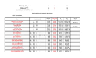
Midship Section Modulus
- 1. 59 m = 5942 cm 11 m = 1100 cm 5 m = 500 cm 2.5 m = 250 cm Above Assumed Axis Area (cm 2 ) Lever (cm) AY AY 2 Ah 2 /12 A Y cm3 cm4 cm4 Expansion Trunk deck plate 8 mm 319.82 349.38 111738.71 39039271.06 Hatch Coaming Plate 12 mm 103.20 304.38 31412.02 9561189.43 796765.79 Deck Stringer plate 10 mm 153.29 104.79 16062.79 1683204.50 Shearstrake Plate 10 mm 61.00 225.50 13755.50 3101865.25 Side Shell Plate 8.5 mm 165.75 97.50 16160.87 1575684.70 131307.06 Inner Shell plate 9 mm 230.59 128.10 29537.94 3783809.92 Center line BHD Plate 8 mm 141.19 176.50 24919.94 4398352.78 Side Stringer Plate 8 712.00 90.40 64364.80 5818577.92 Deck longitudinal 1 HP 180 X 8 18.84 341.60 6437.32 2198986.93 Deck longitudinal 2 HP 180 X 8 18.84 340.54 6417.28 2185322.49 Deck Girder T 250 X 100 X 10 34.00 334.13 11360.56 3795948.02 Deck longitudinal 3 HP 180 X 8 18.84 336.73 6345.50 2136709.03 Deck longitudinal 4 HP 180 X 8 18.84 333.98 6293.68 2101951.27 Deck stringer longitudinal HP 160 X 7 14.59 243.60 3553.88 865725.27 Outer Shell longitudinal 1 HP 160 X 7 14.59 219.35 3200.10 701941.31 Outer Shell longitudinal 2 HP 160 X 7 14.59 154.35 2251.86 347580.72 Outer Shell longitudinal 3 HP 160 X 7 14.59 24.30 354.51 8614.66 Inner Shell longitudinal 1 HP 160 X 7 14.59 219.35 3200.10 701941.31 inner Shell longitudinal 2 HP 160 X 7 14.59 154.35 2251.86 347580.72 nner Shell longitudinal 3 HP 160 X 7 14.59 24.30 354.51 8614.66 Center Line BHD plate Long. 1 HP 180 x 8 18.85 281.70 5308.92 1495507.34 Center Line BHD plate Long. 2 HP 180 x 8 18.85 219.26 4132.17 906008.76 Center Line BHD plate Long. 3 HP 180 x 8 18.85 154.26 2907.17 448451.96 Scantling (mm) Rule Length of Ship, L = Breadth of Ship, B = Depth of Ship, D = Assumed Neutral Axis height from Keel Item MidShip Section Modulus Calculation
- 2. Center Line BHD plate Long. 3 HP 180 x 8 18.85 24.25 457.06 11084.57 Center Line BHD Horizontal Stiffener T 350 X 150 X 10 44.00 90.50 3982.00 360371.00 2217.72 376761.04 87584295.55 928072.84 Below Assumed Axis Area (cm2 ) Lever (cm) AY AY2 Ah2 /12 A Y cm3 cm4 cm4 Center line BHD Plate(8mm) 8 mm 3.20 4.00 12.80 51.20 Center line BHD Plate(9mm) 9 mm 109.34 129.50 14159.53 1833659.14 Keel Plate 10 mm 59.97 249.40 14956.52 3730155.59 310846.30 Bilge plate 8.5 mm 18.35 192.37 3529.59 678974.04 28290.59 Bottom plate 8.5 mm 306.22 241.70 74012.76 17888736.44 Side plate 8.5 mm 89.25 52.50 4685.63 245995.31 Inner shell plate 9 mm 937.80 52.10 48859.38 2545573.70 Slope plate 9 mm 53.75 127.00 6826.25 866933.75 Inner Bottom plate 9 mm 380.81 149.55 56950.14 8516892.76 Side Girder-01 8 mm 74.32 196.50 14602.67 2869381.74 Side Girder-02 8 mm 67.76 192.35 13032.61 2506808.83 Side Stringer Plate 8 mm 73.12 104.60 7648.35 800017.62 Outer Shell longitudinal 4 HP 160 X 7 14.59 14.59 212.84 3105.11 Inner Shell longitudinal 4 HP 160 X 7 14.59 14.59 212.84 3105.11 Side Stringer Plate Long. HP 160 X 7 14.59 114.67 1672.92 191833.81 Bilge Long. HP 180 X 8 20.64 200.86 4146.59 832867.84 Inner Bottom Longitudinal 1 HP 160 X 7 14.59 159.68 2329.52 371970.05 Inner Bottom Longitudinal 2 HP 160 X 7 14.59 159.68 2329.52 371970.05 Inner Bottom Longitudinal 3 HP 160 X 7 14.59 159.68 2329.52 371970.05 Inner Bottom Longitudinal 4 HP 160 X 7 14.59 159.68 2329.52 371970.05 Bottom Longitudinal 1 HP 160 X 7 14.59 235.60 3437.11 809770.07 Bottom Longitudinal 2 HP 160 X 7 14.59 230.87 3368.15 777600.25 Bottom Longitudinal 3 HP 160 X 7 14.59 228.50 3333.59 761724.52 Bottom Longitudinal 4 HP 160 X 7 14.59 226.14 3299.18 746081.80 Center line BHD Longitudinal 5 HP 180 X 8 18.85 40.74 767.83 31283.01 Center line BHD Longitudinal 6 HP 180 X 8 18.85 105.74 1992.80 210718.37 Scantling (mm)Item
- 3. Bottom transvesr Long. HP 160 X 7 14.59 193.20 2818.73 544567.86 Ceter line BHD Longitudinal (One Side) HP 160 X 7 14.59 206.00 3005.54 619141.24 = 2421.87 296862.43 49502859.27 339136.88 A AY AY2 Ah2 /12 2217.7207 376761.0362 87584295.55 928072.8444 2421.87433 296862.4291 49502859.27 339136.8842 4639.59503 79898.60713 137087154.82 1267209.729 + 1267209.73 138354364.55 = 4639.59503 cm2 = 0.463959503 = 9279.19006 cm2 = 0.927919006 17.22 cm = 0.17 m 2.67 m = 267.22 cm = C m = D m 138354364.55 cm 4 136978428.21 cm 4 273956856.41 cm 4 Section Modulus at Keel = AA cm3 BB cm 3 Total Total Above Assumed NA Now, Location of Actual Neutral Axis above Assumed Neutral Axis = Below Assumed NA Total Area (Half Areax2) Half Area Section Modulus at Main Deck = Location of Actual Neutral Axis above Base = Now, Moment of Inertia about assumed Axis = Now, Moment of Inertia about Actual Axis (one side) = Now, Moment of Inertia about Actual Axis (both sides) = Y to keel = Y to Deck=