Downloaded 306 times

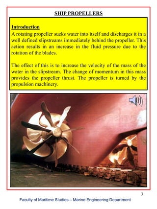
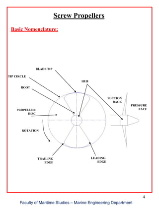
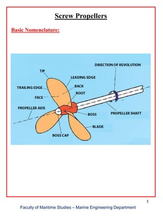
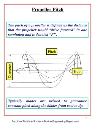

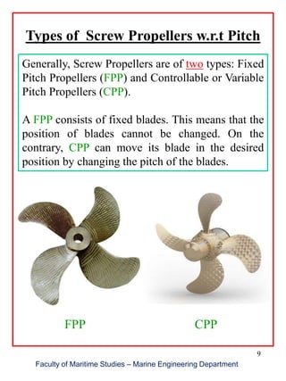

1. Ship propellers work by sucking in water and accelerating it out in a slipstream, using the change in momentum to generate thrust. 2. Screw propellers have key parts like the blade, hub, tip circle, and define characteristics like pitch. Pitch is the theoretical distance traveled per revolution. 3. Propellers can be fixed pitch or variable pitch (controllable), with the latter allowing control of thrust without changing engine power.


![Propulsion%20system %203rd[1]](https://cdn.slidesharecdn.com/ss_thumbnails/propulsion20system-203rd1-140408015635-phpapp01-thumbnail.jpg?width=640&height=640&fit=bounds)


