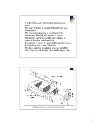
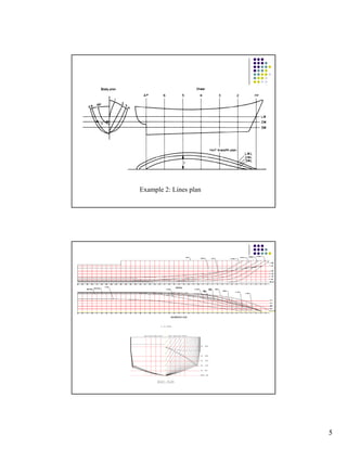
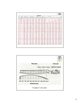
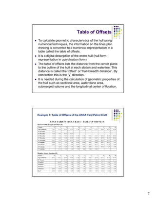
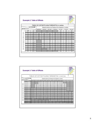
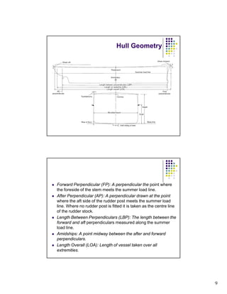
1 
LNB 20303 
Naval Architecture 1 
CHAPTER 2: HULL GEOMETRY 
Prepared by: Muhammad Nasuha Mansor 
Hull Form 
The way to represent hull form? 
The Lines Plan 
What is lines plan???
2 
•A ship's hull is a very complicated 3 dimensional 
shape. 
•The ship's hull form is represented graphically by a 
lines drawing. 
•The lines drawing consist of projections of the 
intersection of the hull with a series of planes. 
•Planes in one dimension will be perpendicular to 
planes in the other two dimensions. 
•these series of planes are projected to represent views 
from the front, top, or side of the ship. 
•This three separate projections, or views, called the 
Body Plan, the Half-Breadth Plan, and the Sheer plan, 
The Projection of Lines onto 3 Orthogonal Planes
3 
The Half-Breadth Plan 
The Profile Plan
4 
The Body Plan 
Example 1: Lines Plan of the USNA Yard Patrol 
Craft
5 
Example 2: Lines plan
6 
Example 3: Lines plan
7 
Table of Offsets 
z To calculate geometric characteristics of the hull using 
numerical techniques, the information on the lines plan 
drawing is converted to a numerical representation in a 
table called the table of offsets. 
z It is a digital description of the entire hull (hull form 
representation in coordination form) 
z The table of offsets lists the distance from the center plane 
to the outline of the hull at each station and waterline. This 
distance is called the ““offset”” or ““half-breadth distance””. By 
convention this is the “y” direction. 
z It is needed during the calculation of geometric properties of 
the hull such as sectional area, waterplane area, 
submerged volume and the longitudinal center of flotation. 
Example 1: Table of Offsets of the USNA Yard Patrol Craft
8 
Example 2: Table of Offsets 
TABLE OF OFFSETS (HALF BREADTH) in metres 
Waterline Name and Distance from Baseline in metres 
BASELINE WL 0.5m WL 1.0m WL 2.0m WL 3.0m WL 4.0m WL 5.0m 
Distance from Station 0 in metres 
TRSM -3.50 3.09 3.09 3.09 
AP 0.00 4.50 4.50 4.50 
0.5 .14 0.29 4.50 4.50 4.50 
1.0 2.28 0.25 0.27 0.27 0.29 4.50 4.50 4.48 
1.5 3.41 0.25 0.27 0.27 2.54 4.50 4.50 4.46 
2.0 4.55 0.25 0.27 0.27 4.24 4.50 4.50 4.45 
2.5 5.69 0.25 0.27 0.27 4.43 4.50 4.50 4.43 
3.0 6.83 0.25 0.27 3.20 4.49 4.50 4.50 4.42 
3.5 7.96 0.25 0.93 3.83 4.50 4.50 4.50 4.41 
4.0 9.10 2.09 4.06 4.50 4.50 4.50 4.41 
5.0 11.38 2.90 4.04 4.50 4.50 4.50 4.40 
6.0 13.65 2.43 3.51 4.16 4.37 4.47 4.46 
Station Name and D 
6.5 14.79 2.04 3.09 3.85 4.20 4.42 4.50 
7.0 15.93 1.59 2.57 3.44 3.92 4.29 4.48 
7.5 17.06 1.14 1.99 2.92 3.52 4.03 4.45 
8.0 18.20 0.74 1.42 2.31 2.98 3.64 4.37 
8.5 19.34 0.37 0.86 1.65 2.33 3.09 4.11 
9.0 20.48 0.38 0.96 1.58 2.37 3.57 
9.5 21.61 0.31 0.77 1.51 2.70 
FP 22.75 0.00 0.33 1.39 
Example 3: Table of Offsets 
T A B L E O F O F F S E T S (H A L F B R E A D T H) i n m e t r e s 
Waterline Name and Distance from Baseline in metres 
BASELINE WL 0.25m WL 0.50m WL 0.75m WL 1.00m WL 1.25m WL 1.50m WL 2.00m WL 2.50m WL 3.00m WL 3.50m WL 4.00m 
Distance from Station 0 in metres 
TRSM -1.20 0.08 2.08 3.42 3.47 3.52 3.62 3.72 
AP 0.00 0.31 2.17 3.42 3.47 3.52 3.62 3.72 
2.0 2.40 0.78 2.34 3.42 3.47 3.52 3.61 3.71 
4.0 4.80 1.12 2.47 3.42 3.47 3.51 3.61 3.70 3.79 
6.0 7.20 0.20 1.38 2.57 3.42 3.46 3.51 3.60 3.69 3.78 
8.0 9.60 0.53 1.59 2.65 3.42 3.46 3.51 3.60 3.68 3.77 
10.0 12.00 0.79 1.75 2.70 3.42 3.46 3.50 3.59 3.68 3.76 
12.0 14.40 0.88 1.76 2.65 3.41 3.46 3.50 3.58 3.67 3.75 
BP 15.40 0.00 0.86 1.72 2.59 3.41 3.45 3.49 3.58 3.66 3.75 
14.0 16.80 0.00 0.83 1.66 2.49 3.40 3.44 3.49 3.57 3.66 3.74 
15.0 18.00 0.00 0.79 1.59 2.38 3.18 3.44 3.48 3.57 3.65 3.74 
16.0 19.20 0.00 0.76 1.51 2.27 3.02 3.43 3.47 3.56 3.64 3.73 
17.0 20.40 0.00 0.71 1.43 2.14 2.85 3.41 3.45 3.54 3.63 3.72 3.80 3.80 
18.0 21.60 0.00 0.67 1.33 2.00 2.67 3.37 3.42 3.51 3.61 3.71 3.80 3.80 
19.0 22.80 0.00 0.62 1.24 1.86 2.48 3.10 3.36 3.47 3.58 3.69 3.80 3.80 
20 0 24 00 0 00 0 55 1 10 1 66 2 21 2 76 3 25 3 38 3 52 3 66 3 80 3 80 
Station Name and D 
20.0 24.00 0.00 0.55 1.10 1.66 2.21 2.76 3.25 3.38 3.52 3.66 3.80 3.80 
21.0 25.20 0.00 0.48 0.95 1.43 1.90 2.38 2.85 3.21 3.40 3.59 3.78 3.80 
22.0 26.40 0.00 0.39 0.79 1.18 1.57 1.97 2.36 2.93 3.20 3.47 3.74 3.78 
23.0 27.60 0.00 0.31 0.62 0.94 1.25 1.56 1.88 2.52 2.88 3.24 3.59 3.69 
24.0 28.80 0.00 0.21 0.43 0.66 0.89 1.13 1.36 1.97 2.40 2.83 3.26 3.43 
24.5 29.40 0.07 0.27 0.47 0.67 0.87 1.08 1.49 2.07 2.55 3.03 3.25 
25.0 30.00 0.03 0.20 0.37 0.55 0.73 1.09 1.67 2.20 2.74 3.02 
FP 30.80 0.00 0.15 0.48 1.02 1.64 2.26 2.66 
26.0 31.20 0.13 0.63 1.29 1.96 2.41 
26.5 31.80 0.69 1.42 2.00 
27.0 32.40 0.38 1.36
9 
Hull Geometry 
z Forward Perpendicular (FP): A perpendicular the point where 
the foreside of the stem meets the summer load line. 
z After Perpendicular (AP): A perpendicular drawn at the point 
where the aft side of the rudder post meets the summer load 
line. Where no rudder post is fitted it is taken as the centre line 
of the rudder stock. 
z Length Between Perpendiculars (LBP): The length between the 
forward and aft perpendiculars measured along the summer 
load line. 
z Amidships: A point midway between the after and forward 
perpendiculars. 
z Length Overall (LOA): Length of vessel taken over all 
extremities.
10 
z Moulded dimensions are often referred to; these are 
taken to the inside of plating on a steel ship.
11 
z Base Line: A horizontal line drawn at the top of the keel 
plate. All vertical moulded dimensions are measured 
relative to this line. 
z Moulded Beam: Measured at the midship section is the 
maximum moulded breadth of the ship. 
z Moulded Draft: Measured from the base line to the 
summer load line at the midship section. 
z Moulded Depth: Measured from the base line to the heel 
of the upper deck beam at the ship’s side amidships. 
z Extreme Beam: The maximum beam taken over all 
extremities. 
z Extreme Draft: Taken from the lowest point of keel to the 
summer load line. Draft marks represent extreme drafts. 
z Extreme Depth: Depth of vessel at ship’s side from 
upper deck to lowest point of keel. 
z Half Breadth: Since a ship’s hull is symmetrical about the 
longitudinal centre line, often only the half beam or half 
breadth at any section is given.
12 
z Freeboard: The difference between the depth at side 
and the draught. It is vertical distance from the waterline 
to the upperside of the deck plating at side 
z Sheer: Tendency of a deck to rise above the horizontal 
in profile. 
z Camber (or Round of Beam): Curvature of decks in the 
transverse direction. Measured as the height of deck at 
centre above the height of deck at side. 
z Rise of Floor (or Deadrise): The rise of the bottom shell 
plating line above the base line. This rise is measured at 
the line of moulded beam. 
z Tumblehome: The inward curvature towards the middle 
line (centerline) of the side shell above the waterline 
z Flare: The outward curvature towards the midle line 
(centerline)of the side shell above the waterline. It 
promotes dryness and is therefore associated with the 
fore end of ship. 
z Stem Rake: Inclination of the stem line from the vertical.
13 
z Last but not least, in the hull geometry definition, there 
are certain coefficients, a e ce a coe c e s, called as form coefficients 
z Non- dimensional 
z They will later used as the values as guide to describe 
the fatness of slimness of the hull, especially below the 
waterline. 
z 4 basic form coefficients are: 
1.Block coefficient, Cb. 
2.Midship coefficient, Cm. 
3.Waterplane area coefficient, Cwp 
4.Prismatic coefficient, Cp 
1. Block coefficient, Cb 
z Gives the ratio of the volume of the underwater body (∇) 
and the rectangular block bounded by length (Lpp), 
breadth (B), and draught (T). 
z A vessel with a small Cb is referred to as ‘fine’ (fast 
ships). 
z Customary values for the Cb of several types of vessel: 
Type Cb Form 
Very fast ship 0.50 - 0.65 Fine 
Ordinary cargo ship 0.65 – 0.75 Moderate 
Slow bulk carrier 0.75 – 0.90 Full
14 
1. Midship coefficient, Cm 
z Ratio of the immersed midship section area (Am) to the 
area of the rectangular having the same breadth and 
draught of the ship. 
z 0.85 fast ship, 0.99 slow ship
15 
1. Waterplane coefficient, Cwp 
z The ratio of the area of the waterplane area to the area 
of the rectangular having a length (L) and a breadth (B) 
equal to the ship moulded breadth. 
1. Prismatic coefficient, Cp 
z The ratio of the volume of displacement to the volume of 
prism (equal to the length between perpendiculars , Lpp 
multiply with a cross- sectional area of the midship, Am 
z Approximate range of values: 0.55 fine ship, 0.85 full 
ship.
16 
SUMMARY 
As groundwork, knowledge of Naval Architecture can be started with 
the familiarization of types of floating objects and ships and how they are 
categorized. Insightful of this part could bring better perspective in going deeper 
about Naval Architecture study. At the same time terminologies and geometries 
of the typical ship, progressively can be digested. 
Types of floating objects and ships basically are categorized in several 
ways. It can be possibly classed base on the functions, and some references 
clustered the types of ship according to their means of physical support while 
in operation. Three broad classifications that are frequently used by naval 
architects are aerostatic support, hydrodynamic support and hydrostatic 
support. 
Definitely with the well briefed of basic terminologies and geometries 
of the ship will be helpful for learner to further explore about the naval 
architecture. The earliest drawing in this study that should be discussed is called 
a lines plan drawing. A ship's hull basically is a very complicated 3 dimensional 
shape. The lines plan graphically represents this hull form in scaled 2D view. 
The drawing usually displays information in three reference planes. These 
series of planes are projected to represent views from the front, top, or side of 
the ship. 
In marine terminology, it is called the Body Plan, the Half-Breadth 
Plan, and the Sheer plan (sometimes known as Profile plan). The basic 
lines plan consists of three (3) reference lines drawn in each of those views. 
They are station lines, buttock lines and waterlines. Besides, lines plan 
drawing should also include principle dimensions of that particular ship. This 
basically describes a size of the ship in term of length, breadth, height and many 
more. 
This lines plan drawing can also be interpreted into numerical 
presentation. It is called a table of offsets. Table of offsets is a digital 
description of the entire hull form, represents in coordinates form. It is needed 
in order to calculate geometrics of the hull using numerical techniques, 
which mainly a part of the naval architecture works. 
The completed lines plan drawing and table of offsets basically will be 
the main input to proceed with the next stage. Hydrostatics calculation is one of 
the earliest parts in naval architecture study, and can be determined right after 
the lines plan and table of offsets are generated.

Hull form geometry

  • 1.
    1 LNB 20303 Naval Architecture 1 CHAPTER 2: HULL GEOMETRY Prepared by: Muhammad Nasuha Mansor Hull Form The way to represent hull form? The Lines Plan What is lines plan???
  • 2.
    2 •A ship'shull is a very complicated 3 dimensional shape. •The ship's hull form is represented graphically by a lines drawing. •The lines drawing consist of projections of the intersection of the hull with a series of planes. •Planes in one dimension will be perpendicular to planes in the other two dimensions. •these series of planes are projected to represent views from the front, top, or side of the ship. •This three separate projections, or views, called the Body Plan, the Half-Breadth Plan, and the Sheer plan, The Projection of Lines onto 3 Orthogonal Planes
  • 3.
    3 The Half-BreadthPlan The Profile Plan
  • 4.
    4 The BodyPlan Example 1: Lines Plan of the USNA Yard Patrol Craft
  • 5.
    5 Example 2:Lines plan
  • 6.
    6 Example 3:Lines plan
  • 7.
    7 Table ofOffsets z To calculate geometric characteristics of the hull using numerical techniques, the information on the lines plan drawing is converted to a numerical representation in a table called the table of offsets. z It is a digital description of the entire hull (hull form representation in coordination form) z The table of offsets lists the distance from the center plane to the outline of the hull at each station and waterline. This distance is called the ““offset”” or ““half-breadth distance””. By convention this is the “y” direction. z It is needed during the calculation of geometric properties of the hull such as sectional area, waterplane area, submerged volume and the longitudinal center of flotation. Example 1: Table of Offsets of the USNA Yard Patrol Craft
  • 8.
    8 Example 2:Table of Offsets TABLE OF OFFSETS (HALF BREADTH) in metres Waterline Name and Distance from Baseline in metres BASELINE WL 0.5m WL 1.0m WL 2.0m WL 3.0m WL 4.0m WL 5.0m Distance from Station 0 in metres TRSM -3.50 3.09 3.09 3.09 AP 0.00 4.50 4.50 4.50 0.5 .14 0.29 4.50 4.50 4.50 1.0 2.28 0.25 0.27 0.27 0.29 4.50 4.50 4.48 1.5 3.41 0.25 0.27 0.27 2.54 4.50 4.50 4.46 2.0 4.55 0.25 0.27 0.27 4.24 4.50 4.50 4.45 2.5 5.69 0.25 0.27 0.27 4.43 4.50 4.50 4.43 3.0 6.83 0.25 0.27 3.20 4.49 4.50 4.50 4.42 3.5 7.96 0.25 0.93 3.83 4.50 4.50 4.50 4.41 4.0 9.10 2.09 4.06 4.50 4.50 4.50 4.41 5.0 11.38 2.90 4.04 4.50 4.50 4.50 4.40 6.0 13.65 2.43 3.51 4.16 4.37 4.47 4.46 Station Name and D 6.5 14.79 2.04 3.09 3.85 4.20 4.42 4.50 7.0 15.93 1.59 2.57 3.44 3.92 4.29 4.48 7.5 17.06 1.14 1.99 2.92 3.52 4.03 4.45 8.0 18.20 0.74 1.42 2.31 2.98 3.64 4.37 8.5 19.34 0.37 0.86 1.65 2.33 3.09 4.11 9.0 20.48 0.38 0.96 1.58 2.37 3.57 9.5 21.61 0.31 0.77 1.51 2.70 FP 22.75 0.00 0.33 1.39 Example 3: Table of Offsets T A B L E O F O F F S E T S (H A L F B R E A D T H) i n m e t r e s Waterline Name and Distance from Baseline in metres BASELINE WL 0.25m WL 0.50m WL 0.75m WL 1.00m WL 1.25m WL 1.50m WL 2.00m WL 2.50m WL 3.00m WL 3.50m WL 4.00m Distance from Station 0 in metres TRSM -1.20 0.08 2.08 3.42 3.47 3.52 3.62 3.72 AP 0.00 0.31 2.17 3.42 3.47 3.52 3.62 3.72 2.0 2.40 0.78 2.34 3.42 3.47 3.52 3.61 3.71 4.0 4.80 1.12 2.47 3.42 3.47 3.51 3.61 3.70 3.79 6.0 7.20 0.20 1.38 2.57 3.42 3.46 3.51 3.60 3.69 3.78 8.0 9.60 0.53 1.59 2.65 3.42 3.46 3.51 3.60 3.68 3.77 10.0 12.00 0.79 1.75 2.70 3.42 3.46 3.50 3.59 3.68 3.76 12.0 14.40 0.88 1.76 2.65 3.41 3.46 3.50 3.58 3.67 3.75 BP 15.40 0.00 0.86 1.72 2.59 3.41 3.45 3.49 3.58 3.66 3.75 14.0 16.80 0.00 0.83 1.66 2.49 3.40 3.44 3.49 3.57 3.66 3.74 15.0 18.00 0.00 0.79 1.59 2.38 3.18 3.44 3.48 3.57 3.65 3.74 16.0 19.20 0.00 0.76 1.51 2.27 3.02 3.43 3.47 3.56 3.64 3.73 17.0 20.40 0.00 0.71 1.43 2.14 2.85 3.41 3.45 3.54 3.63 3.72 3.80 3.80 18.0 21.60 0.00 0.67 1.33 2.00 2.67 3.37 3.42 3.51 3.61 3.71 3.80 3.80 19.0 22.80 0.00 0.62 1.24 1.86 2.48 3.10 3.36 3.47 3.58 3.69 3.80 3.80 20 0 24 00 0 00 0 55 1 10 1 66 2 21 2 76 3 25 3 38 3 52 3 66 3 80 3 80 Station Name and D 20.0 24.00 0.00 0.55 1.10 1.66 2.21 2.76 3.25 3.38 3.52 3.66 3.80 3.80 21.0 25.20 0.00 0.48 0.95 1.43 1.90 2.38 2.85 3.21 3.40 3.59 3.78 3.80 22.0 26.40 0.00 0.39 0.79 1.18 1.57 1.97 2.36 2.93 3.20 3.47 3.74 3.78 23.0 27.60 0.00 0.31 0.62 0.94 1.25 1.56 1.88 2.52 2.88 3.24 3.59 3.69 24.0 28.80 0.00 0.21 0.43 0.66 0.89 1.13 1.36 1.97 2.40 2.83 3.26 3.43 24.5 29.40 0.07 0.27 0.47 0.67 0.87 1.08 1.49 2.07 2.55 3.03 3.25 25.0 30.00 0.03 0.20 0.37 0.55 0.73 1.09 1.67 2.20 2.74 3.02 FP 30.80 0.00 0.15 0.48 1.02 1.64 2.26 2.66 26.0 31.20 0.13 0.63 1.29 1.96 2.41 26.5 31.80 0.69 1.42 2.00 27.0 32.40 0.38 1.36
  • 9.
    9 Hull Geometry z Forward Perpendicular (FP): A perpendicular the point where the foreside of the stem meets the summer load line. z After Perpendicular (AP): A perpendicular drawn at the point where the aft side of the rudder post meets the summer load line. Where no rudder post is fitted it is taken as the centre line of the rudder stock. z Length Between Perpendiculars (LBP): The length between the forward and aft perpendiculars measured along the summer load line. z Amidships: A point midway between the after and forward perpendiculars. z Length Overall (LOA): Length of vessel taken over all extremities.
  • 10.
    10 z Mouldeddimensions are often referred to; these are taken to the inside of plating on a steel ship.
  • 11.
    11 z BaseLine: A horizontal line drawn at the top of the keel plate. All vertical moulded dimensions are measured relative to this line. z Moulded Beam: Measured at the midship section is the maximum moulded breadth of the ship. z Moulded Draft: Measured from the base line to the summer load line at the midship section. z Moulded Depth: Measured from the base line to the heel of the upper deck beam at the ship’s side amidships. z Extreme Beam: The maximum beam taken over all extremities. z Extreme Draft: Taken from the lowest point of keel to the summer load line. Draft marks represent extreme drafts. z Extreme Depth: Depth of vessel at ship’s side from upper deck to lowest point of keel. z Half Breadth: Since a ship’s hull is symmetrical about the longitudinal centre line, often only the half beam or half breadth at any section is given.
  • 12.
    12 z Freeboard:The difference between the depth at side and the draught. It is vertical distance from the waterline to the upperside of the deck plating at side z Sheer: Tendency of a deck to rise above the horizontal in profile. z Camber (or Round of Beam): Curvature of decks in the transverse direction. Measured as the height of deck at centre above the height of deck at side. z Rise of Floor (or Deadrise): The rise of the bottom shell plating line above the base line. This rise is measured at the line of moulded beam. z Tumblehome: The inward curvature towards the middle line (centerline) of the side shell above the waterline z Flare: The outward curvature towards the midle line (centerline)of the side shell above the waterline. It promotes dryness and is therefore associated with the fore end of ship. z Stem Rake: Inclination of the stem line from the vertical.
  • 13.
    13 z Lastbut not least, in the hull geometry definition, there are certain coefficients, a e ce a coe c e s, called as form coefficients z Non- dimensional z They will later used as the values as guide to describe the fatness of slimness of the hull, especially below the waterline. z 4 basic form coefficients are: 1.Block coefficient, Cb. 2.Midship coefficient, Cm. 3.Waterplane area coefficient, Cwp 4.Prismatic coefficient, Cp 1. Block coefficient, Cb z Gives the ratio of the volume of the underwater body (∇) and the rectangular block bounded by length (Lpp), breadth (B), and draught (T). z A vessel with a small Cb is referred to as ‘fine’ (fast ships). z Customary values for the Cb of several types of vessel: Type Cb Form Very fast ship 0.50 - 0.65 Fine Ordinary cargo ship 0.65 – 0.75 Moderate Slow bulk carrier 0.75 – 0.90 Full
  • 14.
    14 1. Midshipcoefficient, Cm z Ratio of the immersed midship section area (Am) to the area of the rectangular having the same breadth and draught of the ship. z 0.85 fast ship, 0.99 slow ship
  • 15.
    15 1. Waterplanecoefficient, Cwp z The ratio of the area of the waterplane area to the area of the rectangular having a length (L) and a breadth (B) equal to the ship moulded breadth. 1. Prismatic coefficient, Cp z The ratio of the volume of displacement to the volume of prism (equal to the length between perpendiculars , Lpp multiply with a cross- sectional area of the midship, Am z Approximate range of values: 0.55 fine ship, 0.85 full ship.
  • 16.
    16 SUMMARY Asgroundwork, knowledge of Naval Architecture can be started with the familiarization of types of floating objects and ships and how they are categorized. Insightful of this part could bring better perspective in going deeper about Naval Architecture study. At the same time terminologies and geometries of the typical ship, progressively can be digested. Types of floating objects and ships basically are categorized in several ways. It can be possibly classed base on the functions, and some references clustered the types of ship according to their means of physical support while in operation. Three broad classifications that are frequently used by naval architects are aerostatic support, hydrodynamic support and hydrostatic support. Definitely with the well briefed of basic terminologies and geometries of the ship will be helpful for learner to further explore about the naval architecture. The earliest drawing in this study that should be discussed is called a lines plan drawing. A ship's hull basically is a very complicated 3 dimensional shape. The lines plan graphically represents this hull form in scaled 2D view. The drawing usually displays information in three reference planes. These series of planes are projected to represent views from the front, top, or side of the ship. In marine terminology, it is called the Body Plan, the Half-Breadth Plan, and the Sheer plan (sometimes known as Profile plan). The basic lines plan consists of three (3) reference lines drawn in each of those views. They are station lines, buttock lines and waterlines. Besides, lines plan drawing should also include principle dimensions of that particular ship. This basically describes a size of the ship in term of length, breadth, height and many more. This lines plan drawing can also be interpreted into numerical presentation. It is called a table of offsets. Table of offsets is a digital description of the entire hull form, represents in coordinates form. It is needed in order to calculate geometrics of the hull using numerical techniques, which mainly a part of the naval architecture works. The completed lines plan drawing and table of offsets basically will be the main input to proceed with the next stage. Hydrostatics calculation is one of the earliest parts in naval architecture study, and can be determined right after the lines plan and table of offsets are generated.