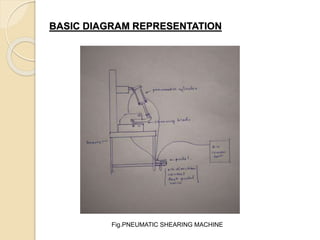
New Horizon Institute of Technology And
Management,Thane
DEPARTMENT OF MECHANICAL ENGINEERING
PROJECT NAME:
“DESIGN AND MANUFACTURING OF PNEUMATIC SHEARING MACHINE”
Presented By:-
1)Mr. Deepak.B.Sonawane
2)Mr. Omkar.S.Baile
3)Mr. Samadhan .P.Bhosale
4)Mr. Omswarup.N.Kotkar
Group No:-ME172105
Introduction
An engineer is always focused towards challenges of bringing
ideas and concepts to the life. Therefore, sophisticated machines
and modern techniques have to be constantly developed and
implemented for economical manufacturing of products. At a same
time , we should also take care that there has been no
compromise with quality and accuracy. In the age of automation
machine became an integral part of human being. By use of
automation it is proved that it gives more production rate than
manual production rate. In competition market everyone wants to
increase production and make there machine multipurpose. New
machines and techniques are developed continuously to
manufacture various products at cheaper rates and high quality .
So we are going to make machine far “SHEET METAL
INDUSTRY” and should be used as circle cutting cum straight
cutting machine. The machine is simple to maintain and easy to
operate . So we tried for “PNEUMATIC SHEARING MACHINE”.
Shearing machine is one of the principal machine in sheet metal
industry. It is mainly used as the name indicates cut strips.
WORKING
 Here advancement of header is carried out in upward
and downward direction using pneumatic double acting
piston and cylinder unit arrangement along with the foot
operated direction control valve . In this type of machine
high pressure air is used as the working fluid for
transfer of power and the motion. To control the to and
fro motion of pneumatic cylinder , the air energy has to
be regulated, controlled, and reversed with a
predetermined sequence in pneumatic system. Similarly
one has to control the quantity of pressure and flow rate
to generate desired level of force and speed of
actuation .To achieve the functions , valves are used to
1)start and stop pneumatic energy 2)control the
direction of flow of compressed air 3)control the flow
rate of compressed air 4)control the pressure rating of
compressed air .
BASIC DIAGRAM REPRESENTATION
Fig.PNEUMATIC SHEARING MACHINE
COMPONENTS OF SHEARING
MACHINE
 1) SHEARING BLADE
 2)PNEUMATIC CYLINDER
 3)5/2 DIRECTION CONTROL FOOT
OPERATED VALVE
 4)AIR CIRCULATING DEVICES
 5)FRAME
SCOPES AND OBJECTIVES
 A roller can be attaches before blade
for feeding the metal sheets.
 Heat sensor can be attached on
machine to avoid damage of blade.
 Special way and scrap storing system
can be made
 Glass covering can be done to avoid
the injury while operation.
REFERANCES
 1)WORKSHOP TECHNOLOGY-HAZARA
CHOUDHARY
 2)MACHINE DESIGN- R.S.KHURMI
 3)PRODUCTION TECHNOLOGY- BANGA
AND SHARMA
 4)PRODUCTION PLANING AND
CONTROL-BANGA AND SHARMA
 5)HEAT TREATMENT- P.C. SHARMA
 6)INDUSTRIAL HERALD MAGAZINE –
INDUSTRIES ASSOCIATION OF INDIA
THANK YOU

SHEARING MACHINE.pptx

  • 1.
    New Horizon Instituteof Technology And Management,Thane DEPARTMENT OF MECHANICAL ENGINEERING PROJECT NAME: “DESIGN AND MANUFACTURING OF PNEUMATIC SHEARING MACHINE” Presented By:- 1)Mr. Deepak.B.Sonawane 2)Mr. Omkar.S.Baile 3)Mr. Samadhan .P.Bhosale 4)Mr. Omswarup.N.Kotkar Group No:-ME172105
  • 2.
    Introduction An engineer isalways focused towards challenges of bringing ideas and concepts to the life. Therefore, sophisticated machines and modern techniques have to be constantly developed and implemented for economical manufacturing of products. At a same time , we should also take care that there has been no compromise with quality and accuracy. In the age of automation machine became an integral part of human being. By use of automation it is proved that it gives more production rate than manual production rate. In competition market everyone wants to increase production and make there machine multipurpose. New machines and techniques are developed continuously to manufacture various products at cheaper rates and high quality . So we are going to make machine far “SHEET METAL INDUSTRY” and should be used as circle cutting cum straight cutting machine. The machine is simple to maintain and easy to operate . So we tried for “PNEUMATIC SHEARING MACHINE”. Shearing machine is one of the principal machine in sheet metal industry. It is mainly used as the name indicates cut strips.
  • 3.
    WORKING  Here advancementof header is carried out in upward and downward direction using pneumatic double acting piston and cylinder unit arrangement along with the foot operated direction control valve . In this type of machine high pressure air is used as the working fluid for transfer of power and the motion. To control the to and fro motion of pneumatic cylinder , the air energy has to be regulated, controlled, and reversed with a predetermined sequence in pneumatic system. Similarly one has to control the quantity of pressure and flow rate to generate desired level of force and speed of actuation .To achieve the functions , valves are used to 1)start and stop pneumatic energy 2)control the direction of flow of compressed air 3)control the flow rate of compressed air 4)control the pressure rating of compressed air .
  • 4.
  • 5.
    COMPONENTS OF SHEARING MACHINE 1) SHEARING BLADE  2)PNEUMATIC CYLINDER  3)5/2 DIRECTION CONTROL FOOT OPERATED VALVE  4)AIR CIRCULATING DEVICES  5)FRAME
  • 6.
    SCOPES AND OBJECTIVES A roller can be attaches before blade for feeding the metal sheets.  Heat sensor can be attached on machine to avoid damage of blade.  Special way and scrap storing system can be made  Glass covering can be done to avoid the injury while operation.
  • 7.
    REFERANCES  1)WORKSHOP TECHNOLOGY-HAZARA CHOUDHARY 2)MACHINE DESIGN- R.S.KHURMI  3)PRODUCTION TECHNOLOGY- BANGA AND SHARMA  4)PRODUCTION PLANING AND CONTROL-BANGA AND SHARMA  5)HEAT TREATMENT- P.C. SHARMA  6)INDUSTRIAL HERALD MAGAZINE – INDUSTRIES ASSOCIATION OF INDIA
  • 8.