Download to read offline
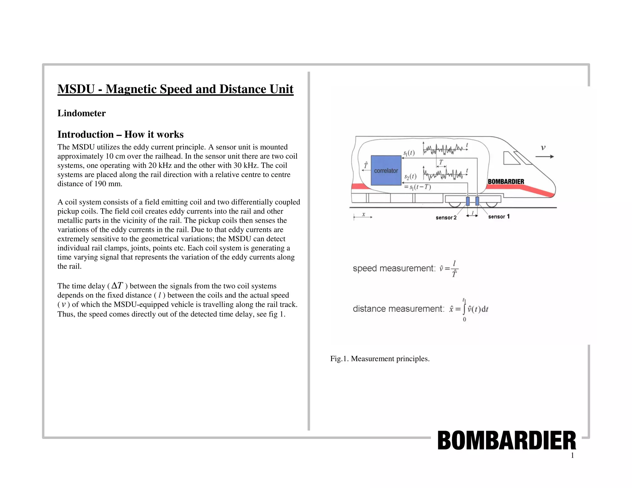
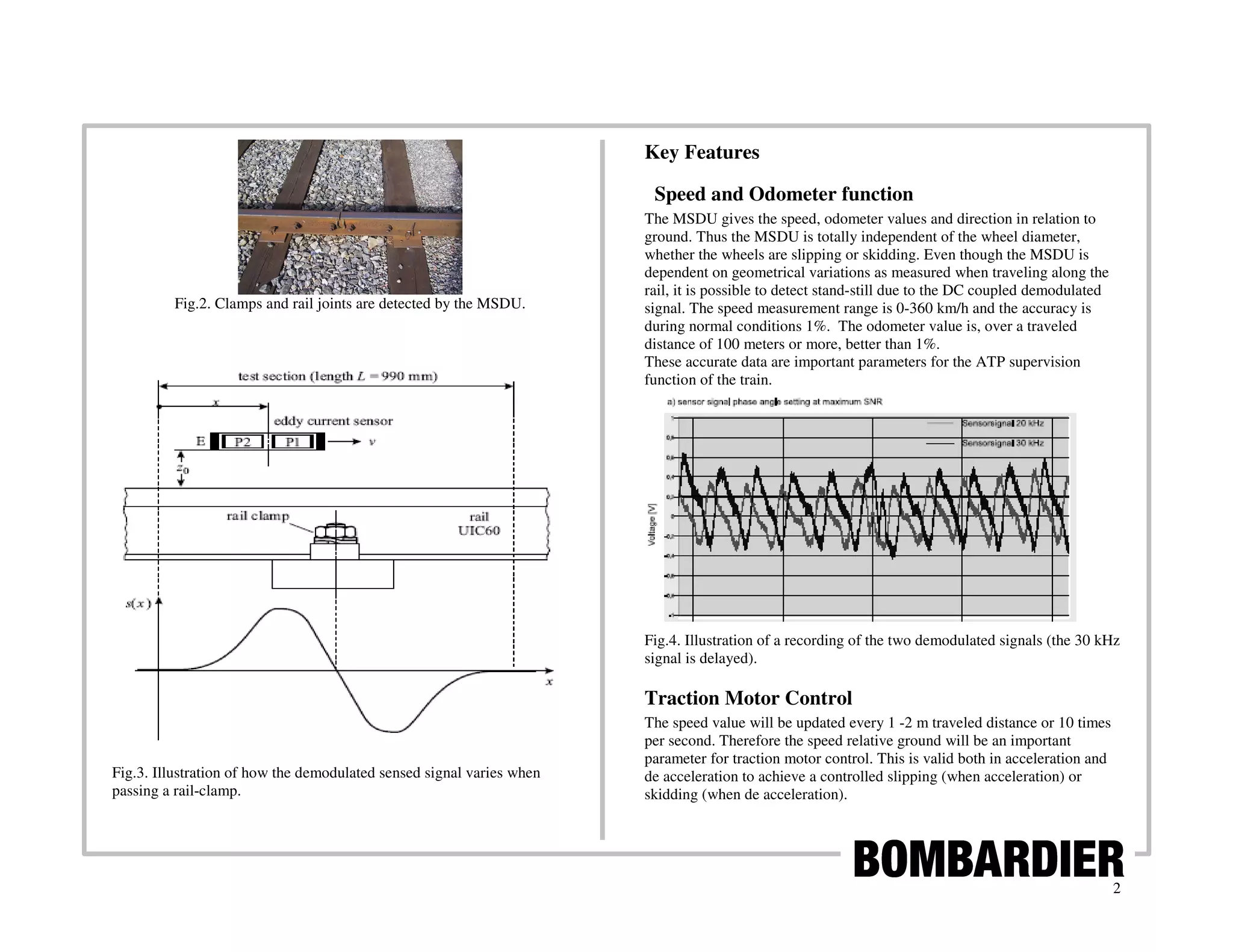
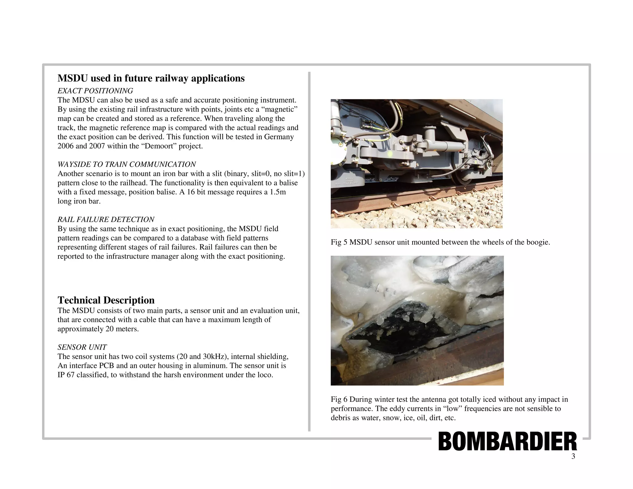
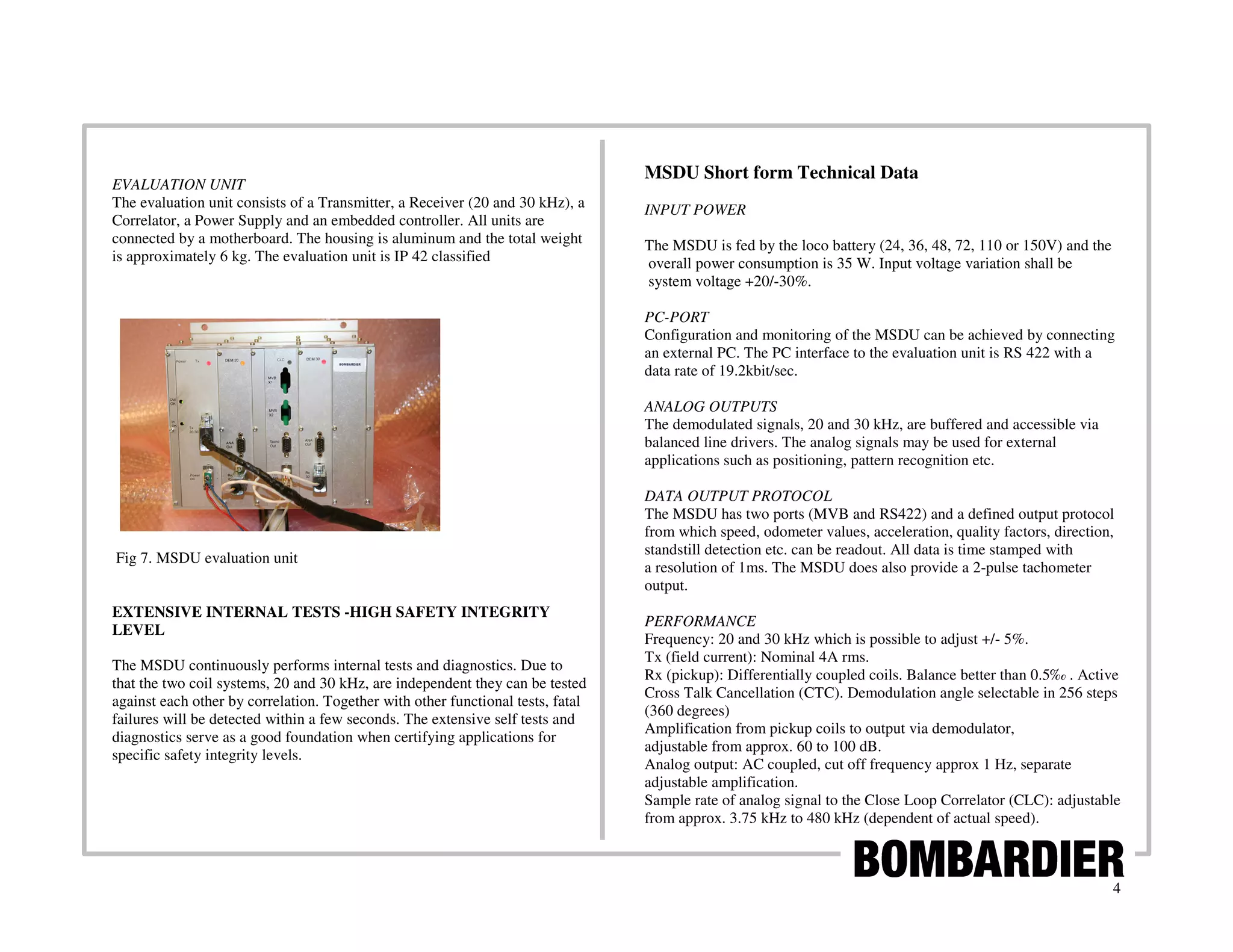

The MSDU utilizes eddy currents to measure speed and distance of a train by sensing variations in the rail. It has two coil systems that detect signals in the rail at different frequencies as the train moves. By measuring the time delay between the signals, the MSDU can calculate speed. It provides accurate, independent speed and odometer readings to control train systems. The MSDU can also detect rail features to determine exact location or identify rail failures. It performs extensive internal testing to ensure safe, reliable operation.


