Download as PPSX, PPTX


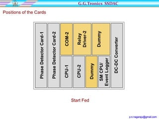


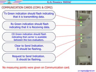


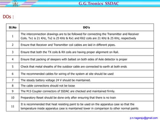


This document provides information on the G.G.Tronics SSDAC axle counting system. It can be configured as a 2DP1S, 3DP1S, 3DP2S, or AS system. The 2DP1S configuration is described for a straight line or block section with start and end fed units communicating over a single pair of quad cable. Diagrams show the typical installation and positions of cards in the evaluator cabinet. The wheel detection principle based on phase detection is explained. Different configurations and their operation are also summarized.


