2
Meteorology
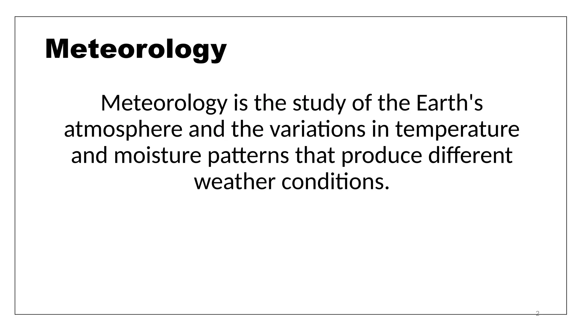
Meteorology is thestudy of the Earth's
atmosphere and the variations in temperature
and moisture patterns that produce different
weather conditions.
3.
3
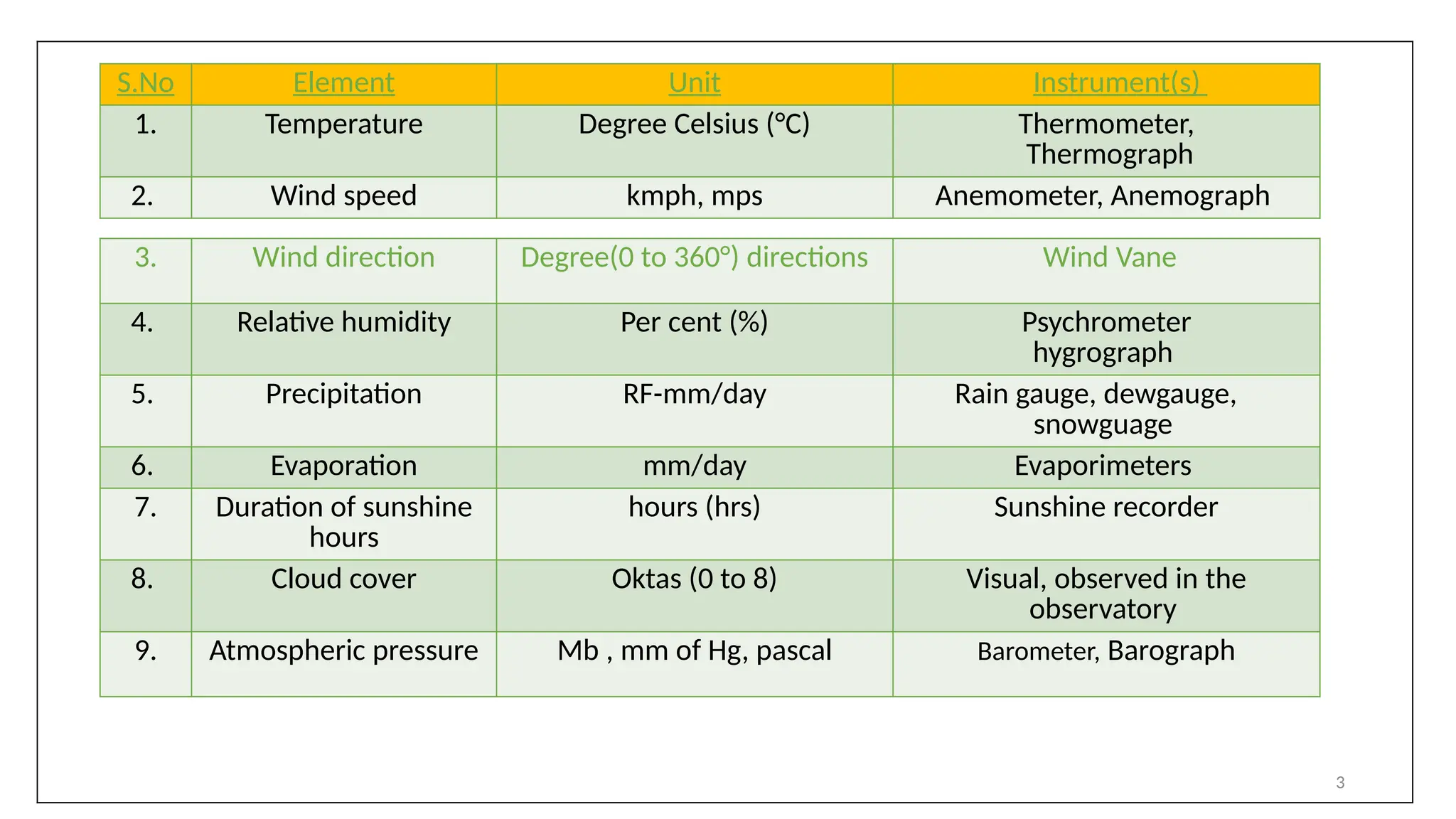
3. Wind directionDegree(0 to 360°) directions Wind Vane
4. Relative humidity Per cent (%) Psychrometer
hygrograph
5. Precipitation RF-mm/day Rain gauge, dewgauge,
snowguage
6. Evaporation mm/day Evaporimeters
7. Duration of sunshine
hours
hours (hrs) Sunshine recorder
8. Cloud cover Oktas (0 to 8) Visual, observed in the
observatory
9. Atmospheric pressure Mb , mm of Hg, pascal Barometer, Barograph
S.No Element Unit Instrument(s)
1. Temperature Degree Celsius (°C) Thermometer,
Thermograph
2. Wind speed kmph, mps Anemometer, Anemograph
4.
4
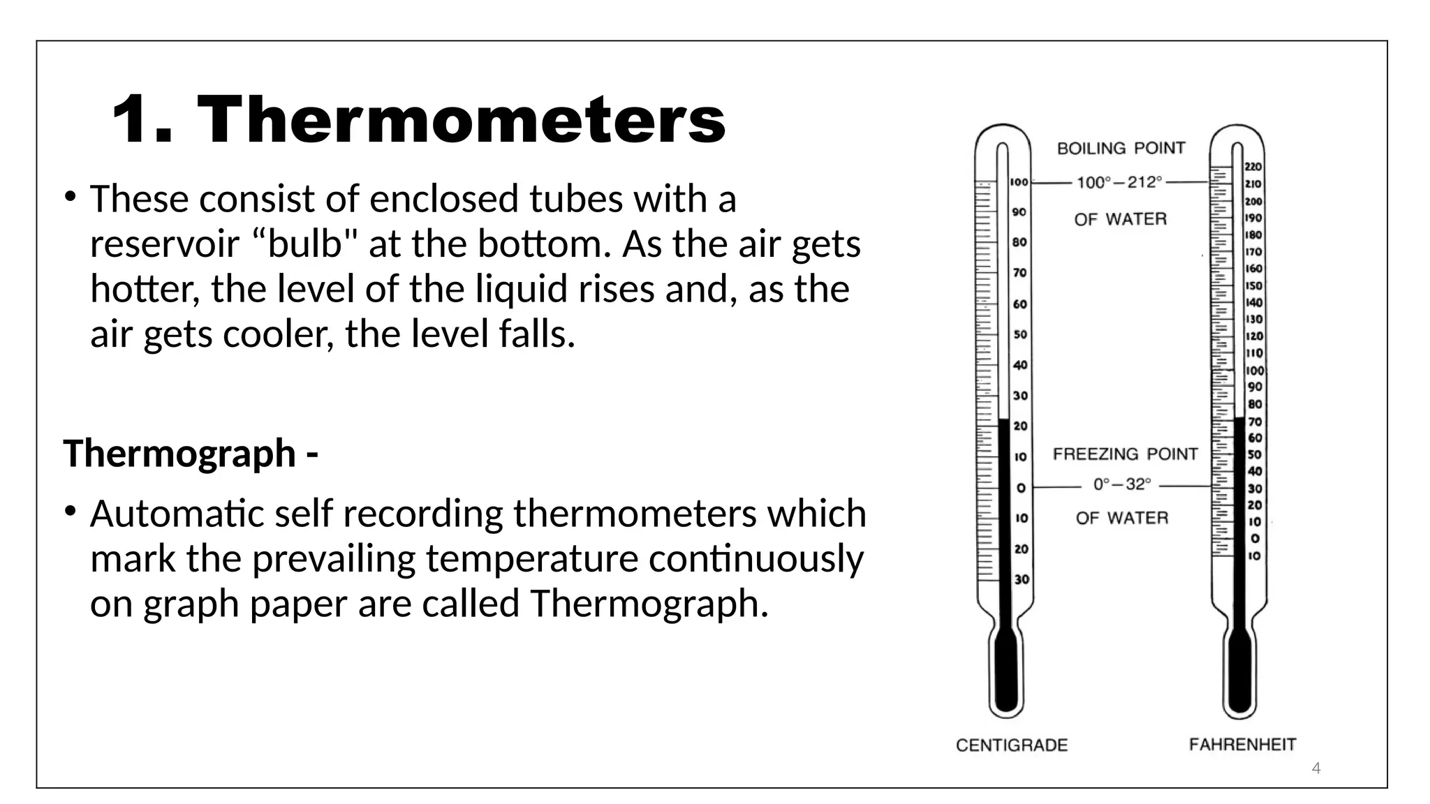
• These consistof enclosed tubes with a
reservoir “bulb" at the bottom. As the air gets
hotter, the level of the liquid rises and, as the
air gets cooler, the level falls.
Thermograph -
• Automatic self recording thermometers which
mark the prevailing temperature continuously
on graph paper are called Thermograph.
1. Thermometers
5.
5
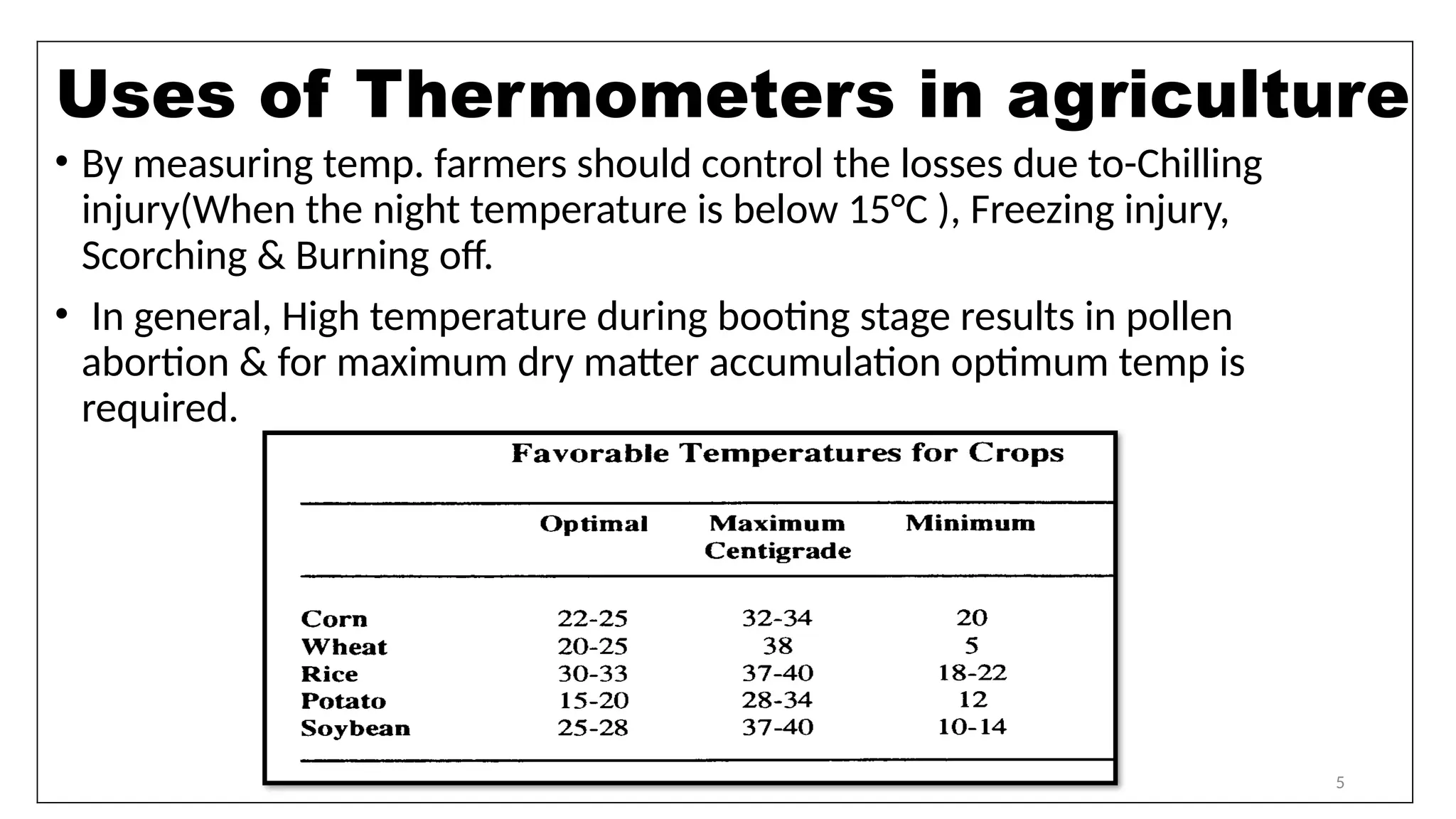
• By measuringtemp. farmers should control the losses due to-Chilling
injury(When the night temperature is below 15°C ), Freezing injury,
Scorching & Burning off.
• In general, High temperature during booting stage results in pollen
abortion & for maximum dry matter accumulation optimum temp is
required.
Uses of Thermometers in agriculture
6.
6
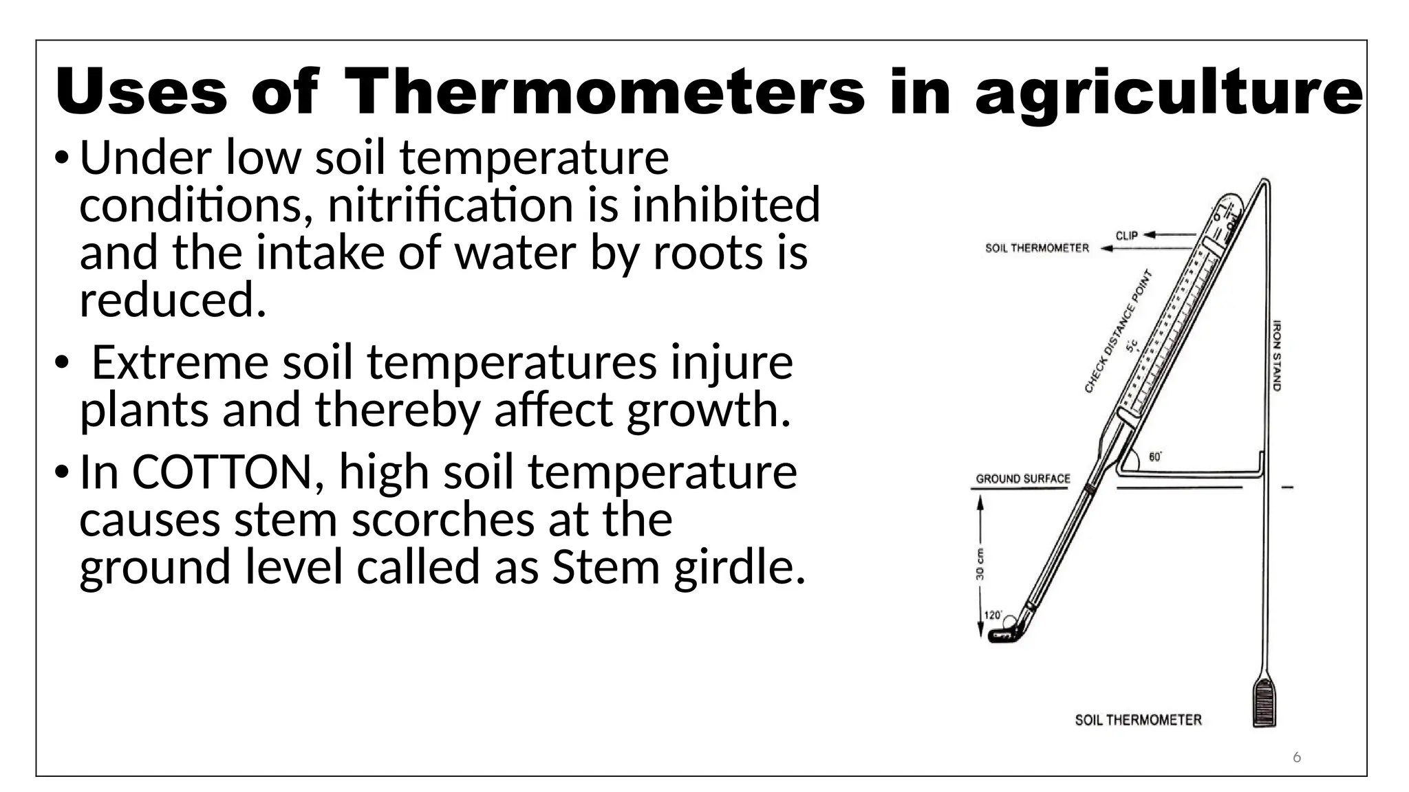
•Under low soiltemperature
conditions, nitrification is inhibited
and the intake of water by roots is
reduced.
• Extreme soil temperatures injure
plants and thereby affect growth.
•In COTTON, high soil temperature
causes stem scorches at the
ground level called as Stem girdle.
Uses of Thermometers in agriculture
7.
7
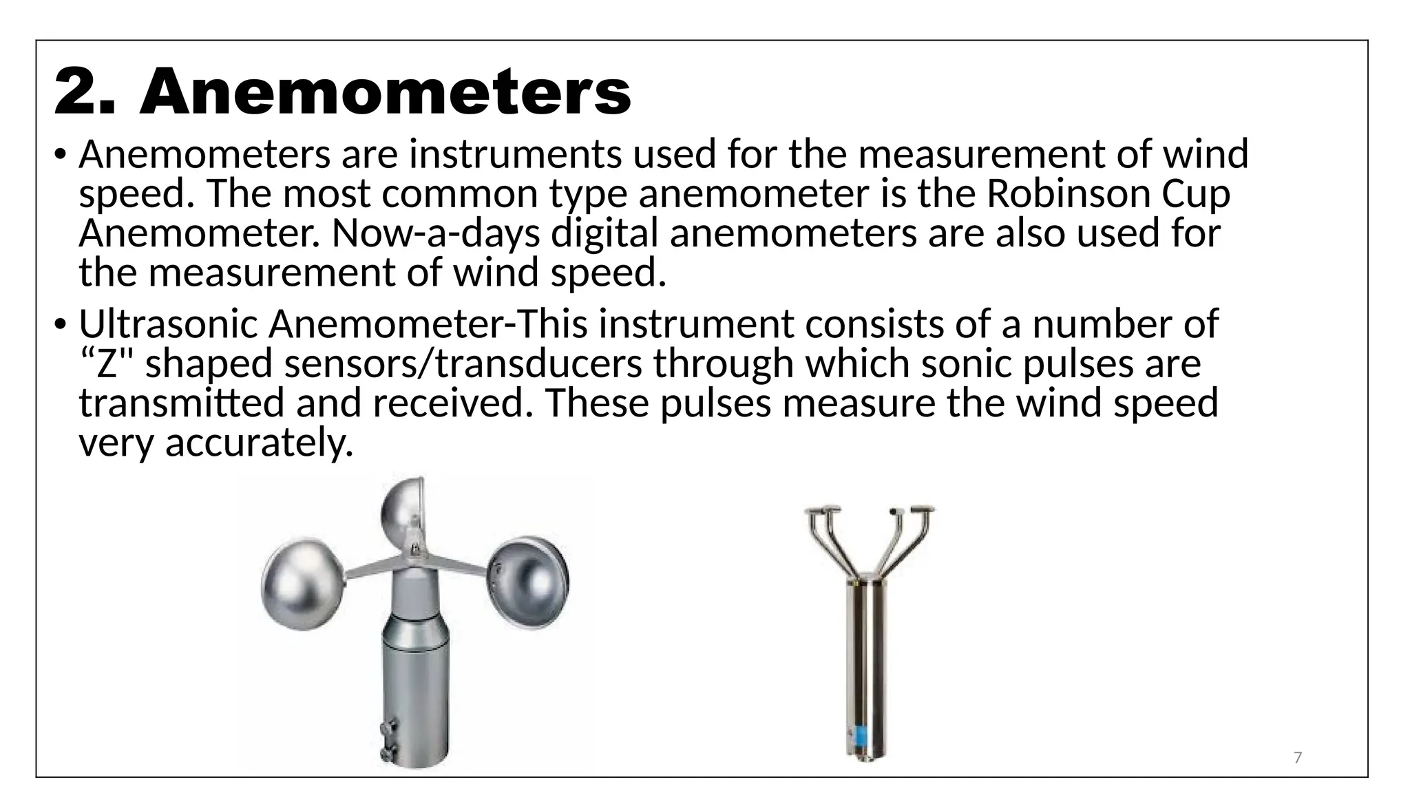
• Anemometers areinstruments used for the measurement of wind
speed. The most common type anemometer is the Robinson Cup
Anemometer. Now-a-days digital anemometers are also used for
the measurement of wind speed.
• Ultrasonic Anemometer-This instrument consists of a number of
“Z" shaped sensors/transducers through which sonic pulses are
transmitted and received. These pulses measure the wind speed
very accurately.
2. Anemometers
8.
8
• It isimportant to know wind speed for spray application and for the design
of wind protection. Early in the morning, when wind speeds are low
(<3kmph), may seem to be a good time to apply herbicides.
• Extreme winds cause mechanical damage to crops (for example, lodging or
leaf damage).
• In general plant growth appears to be inhibited by wind speed more than
10km/hr.
• Moderate turbulence promotes the consumption of CO2 by crops during
photosynthesis.
• Action of wind on soil causes soil erosion and transport of particles and dust.
Uses of Anemometers in agriculture:
9.
9
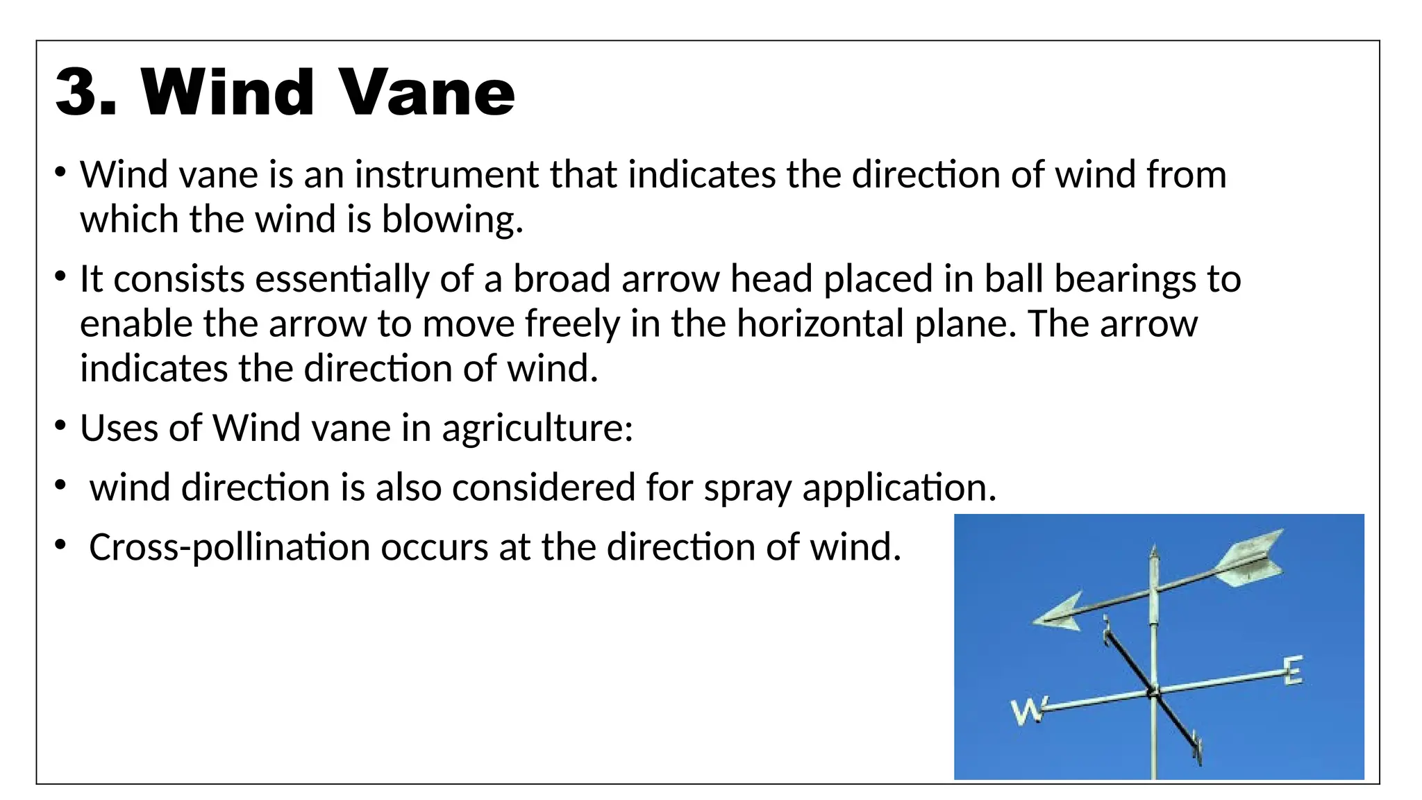
• Wind vaneis an instrument that indicates the direction of wind from
which the wind is blowing.
• It consists essentially of a broad arrow head placed in ball bearings to
enable the arrow to move freely in the horizontal plane. The arrow
indicates the direction of wind.
• Uses of Wind vane in agriculture:
• wind direction is also considered for spray application.
• Cross-pollination occurs at the direction of wind.
3. Wind Vane
10.
10
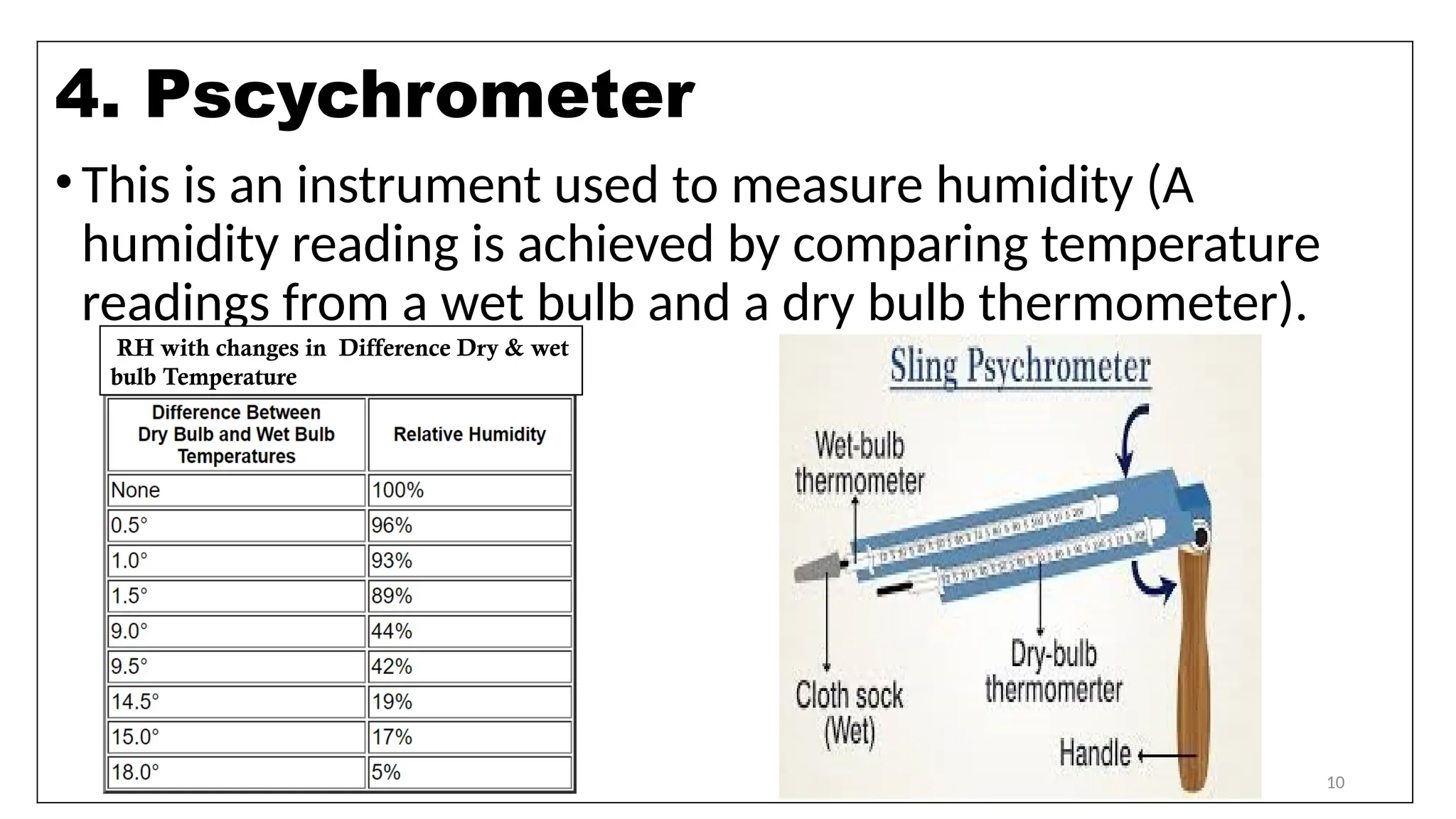
•This is aninstrument used to measure humidity (A
humidity reading is achieved by comparing temperature
readings from a wet bulb and a dry bulb thermometer).
4. Pscychrometer
RH with changes in Difference Dry & wet
bulb Temperature
11.
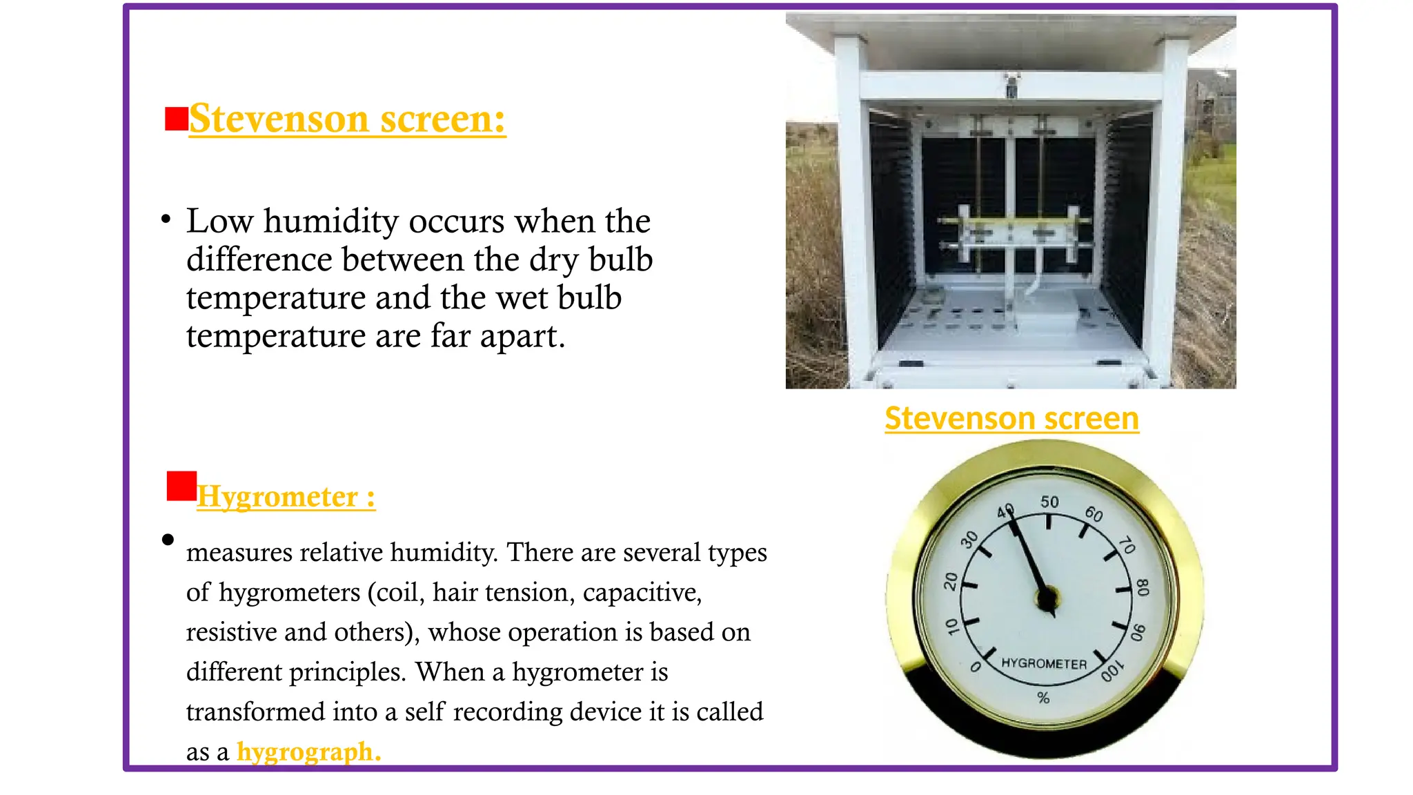
• Other instrumentused to measure RH are-
Stevenson screen:
• Low humidity occurs when the
difference between the dry bulb
temperature and the wet bulb
temperature are far apart.
Hygrometer :
• measures relative humidity. There are several types
of hygrometers (coil, hair tension, capacitive,
resistive and others), whose operation is based on
different principles. When a hygrometer is
transformed into a self recording device it is called
as a hygrograph.
Stevenson screen
12.
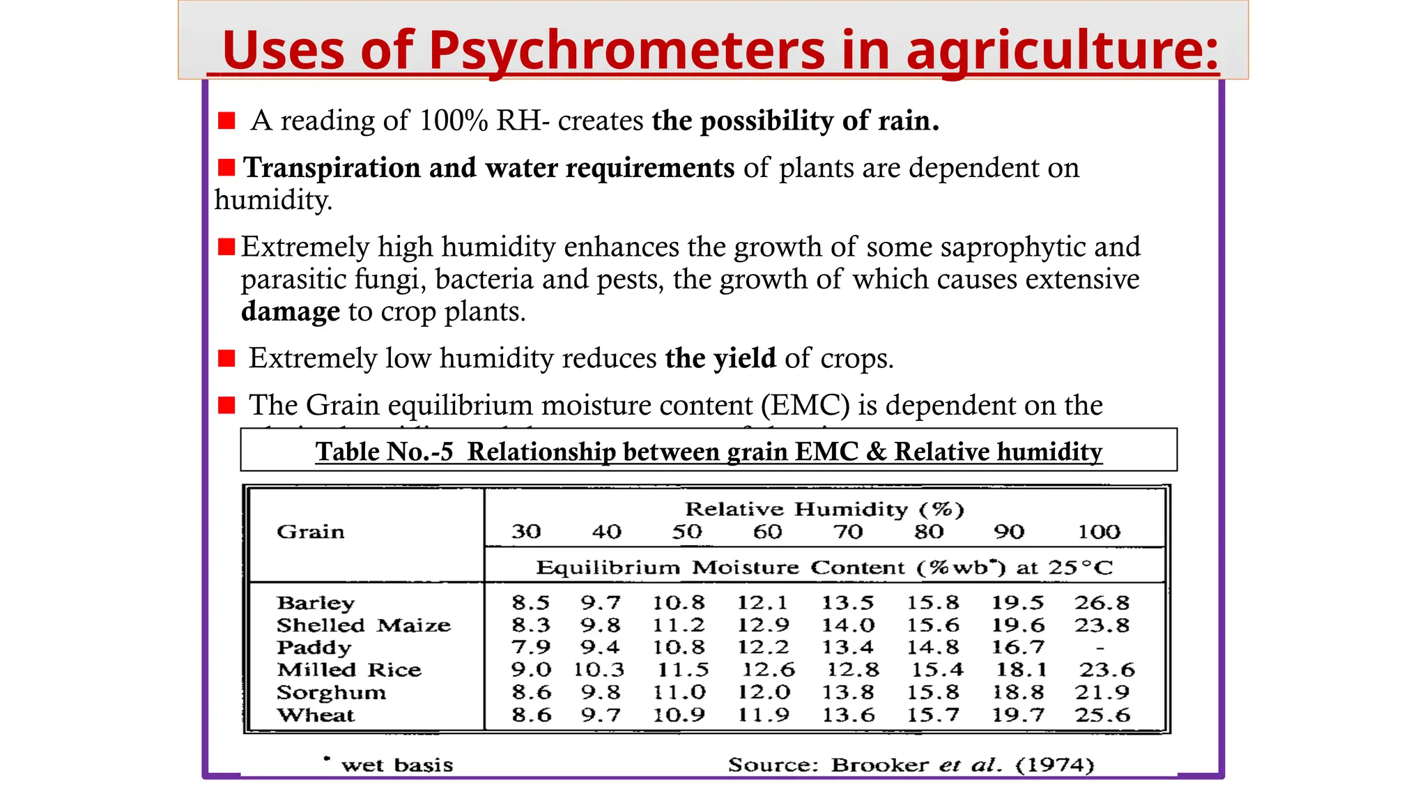
A reading of100% RH- creates the possibility of rain.
Transpiration and water requirements of plants are dependent on
humidity.
Extremely high humidity enhances the growth of some saprophytic and
parasitic fungi, bacteria and pests, the growth of which causes extensive
damage to crop plants.
Extremely low humidity reduces the yield of crops.
The Grain equilibrium moisture content (EMC) is dependent on the
relative humidity and the temperature of the air.
Uses of Psychrometers in agriculture:
Table No.-5 Relationship between grain EMC & Relative humidity
13.
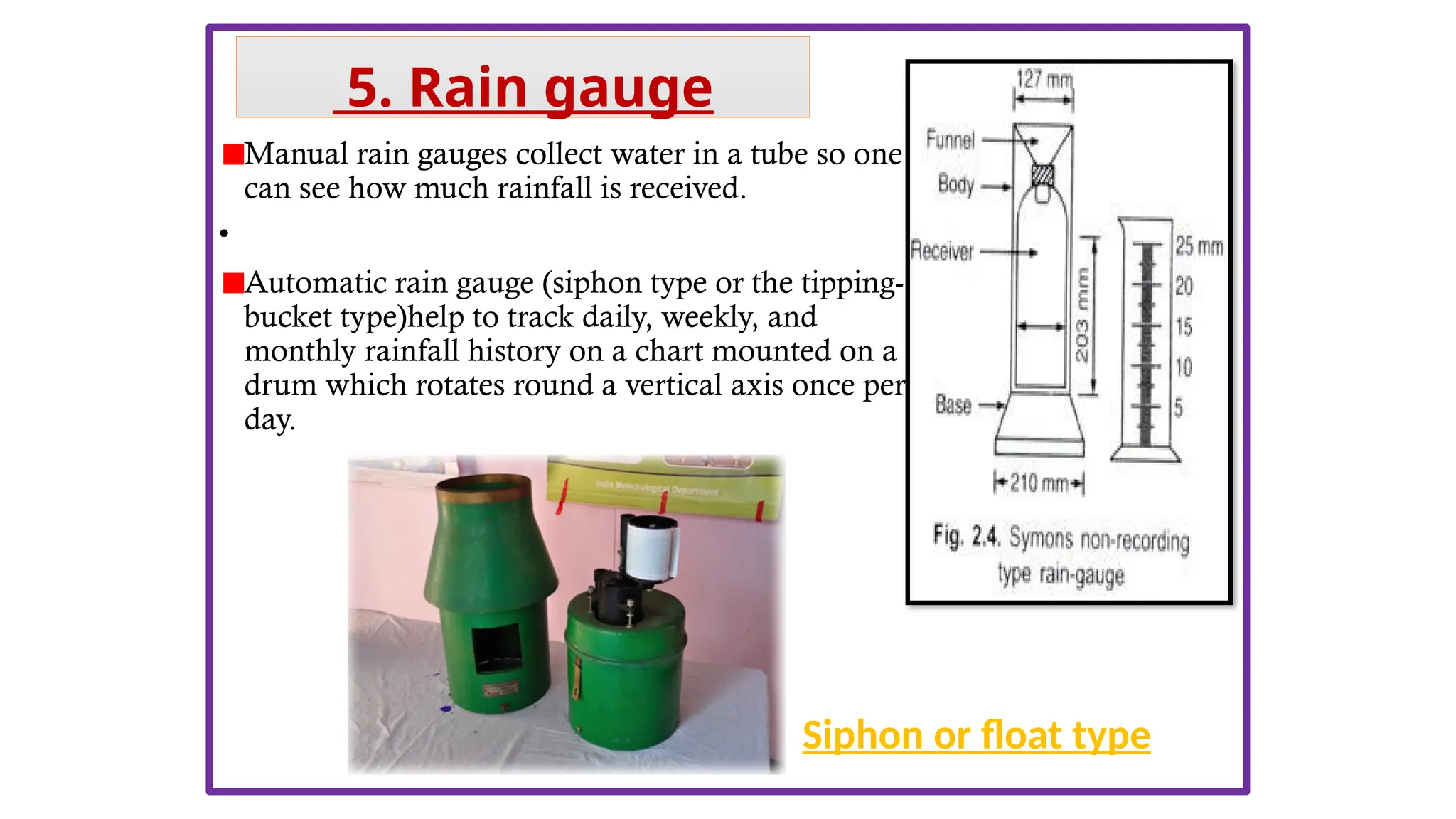
Manual rain gaugescollect water in a tube so one
can see how much rainfall is received.
•
Automatic rain gauge (siphon type or the tipping-
bucket type)help to track daily, weekly, and
monthly rainfall history on a chart mounted on a
drum which rotates round a vertical axis once per
day.
Siphon or float type
5. Rain gauge
14.
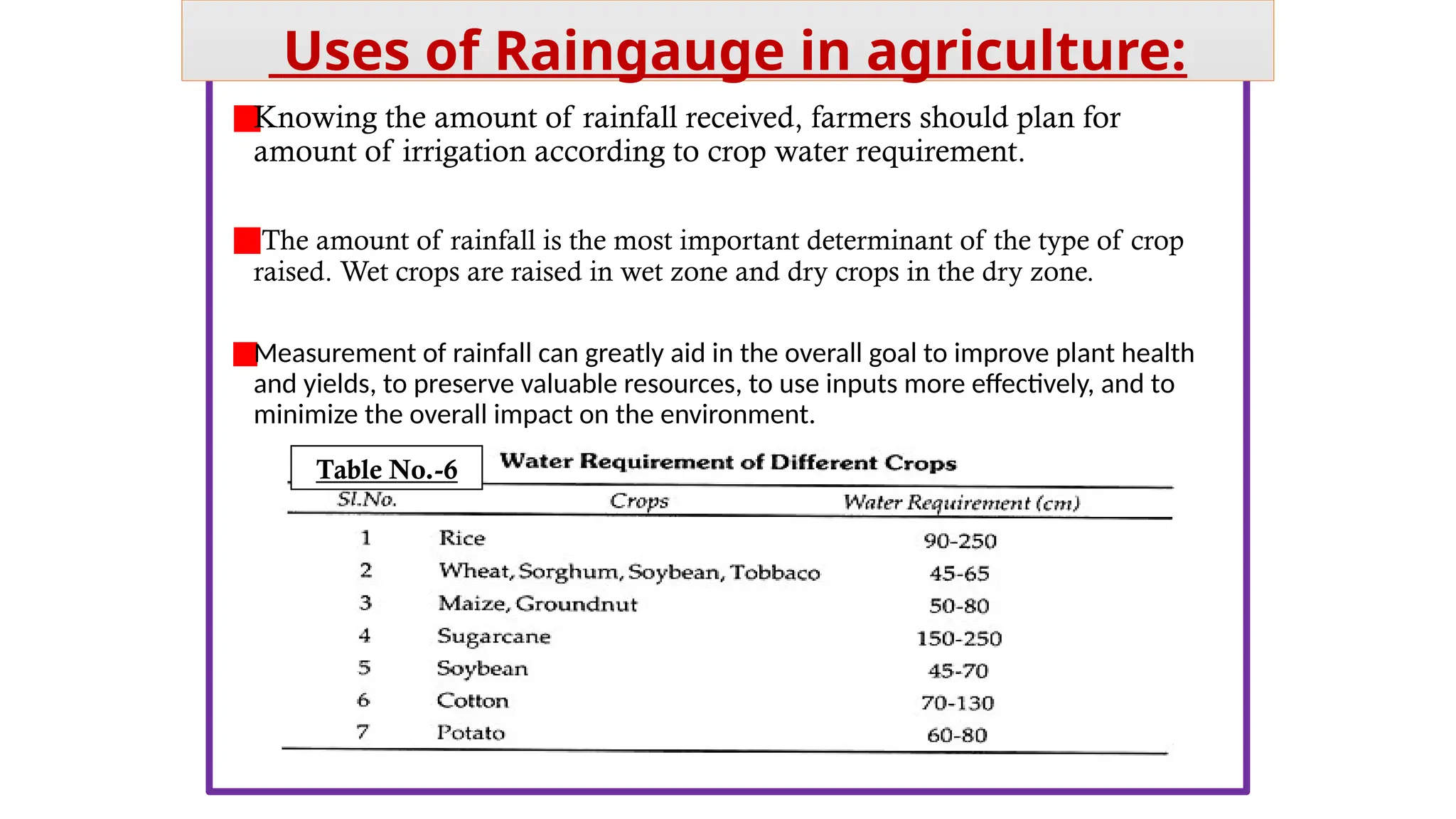
Knowing the amountof rainfall received, farmers should plan for
amount of irrigation according to crop water requirement.
The amount of rainfall is the most important determinant of the type of crop
raised. Wet crops are raised in wet zone and dry crops in the dry zone.
Measurement of rainfall can greatly aid in the overall goal to improve plant health
and yields, to preserve valuable resources, to use inputs more effectively, and to
minimize the overall impact on the environment.
Uses of Raingauge in agriculture:
Table No.-6
15.
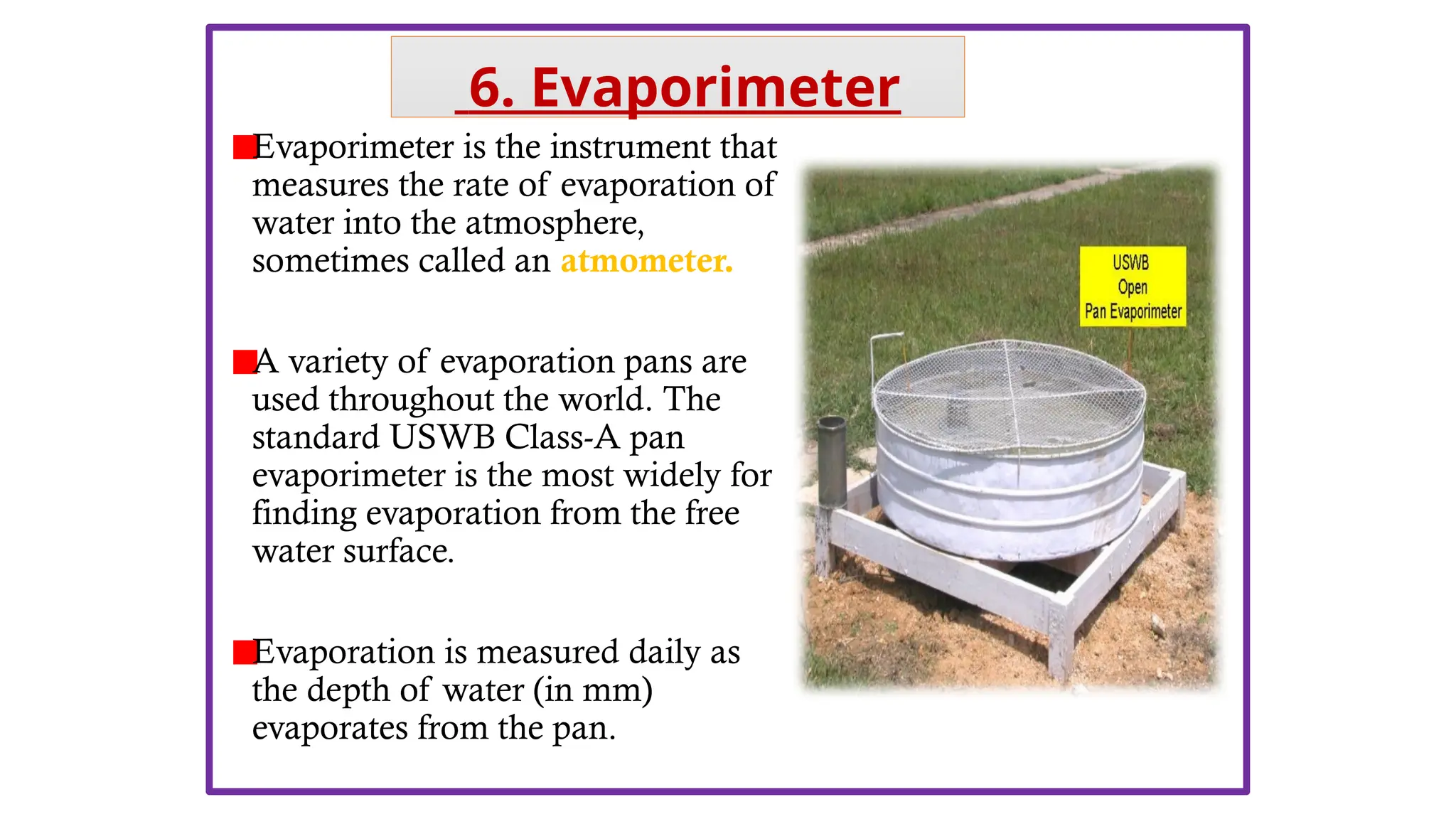
Evaporimeter is theinstrument that
measures the rate of evaporation of
water into the atmosphere,
sometimes called an atmometer.
A variety of evaporation pans are
used throughout the world. The
standard USWB Class-A pan
evaporimeter is the most widely for
finding evaporation from the free
water surface.
Evaporation is measured daily as
the depth of water (in mm)
evaporates from the pan.
6. Evaporimeter
16.
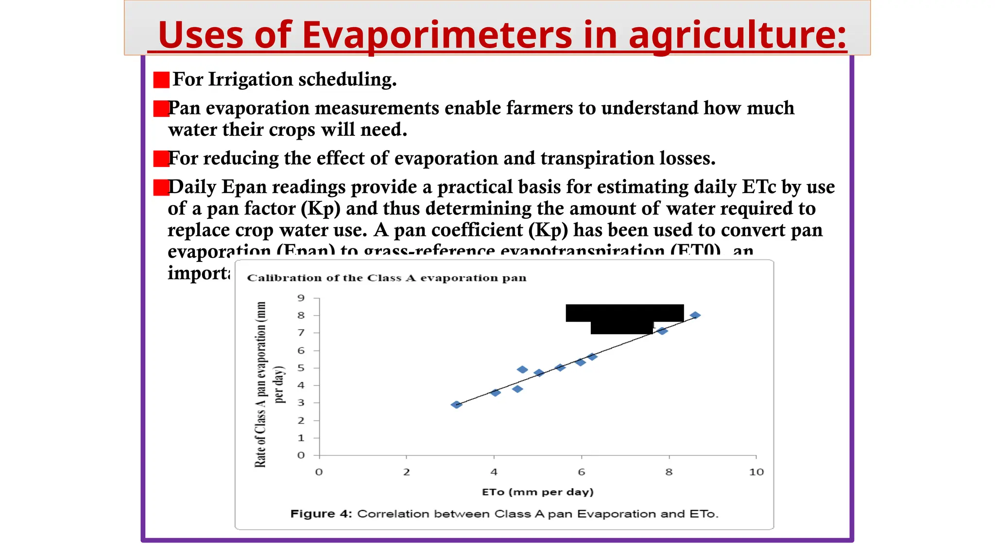
For Irrigation scheduling.
Panevaporation measurements enable farmers to understand how much
water their crops will need.
For reducing the effect of evaporation and transpiration losses.
Daily Epan readings provide a practical basis for estimating daily ETc by use
of a pan factor (Kp) and thus determining the amount of water required to
replace crop water use. A pan coefficient (Kp) has been used to convert pan
evaporation (Epan) to grass-reference evapotranspiration (ET0), an
important component in water management of irrigated crops.
Uses of Evaporimeters in agriculture:
17.
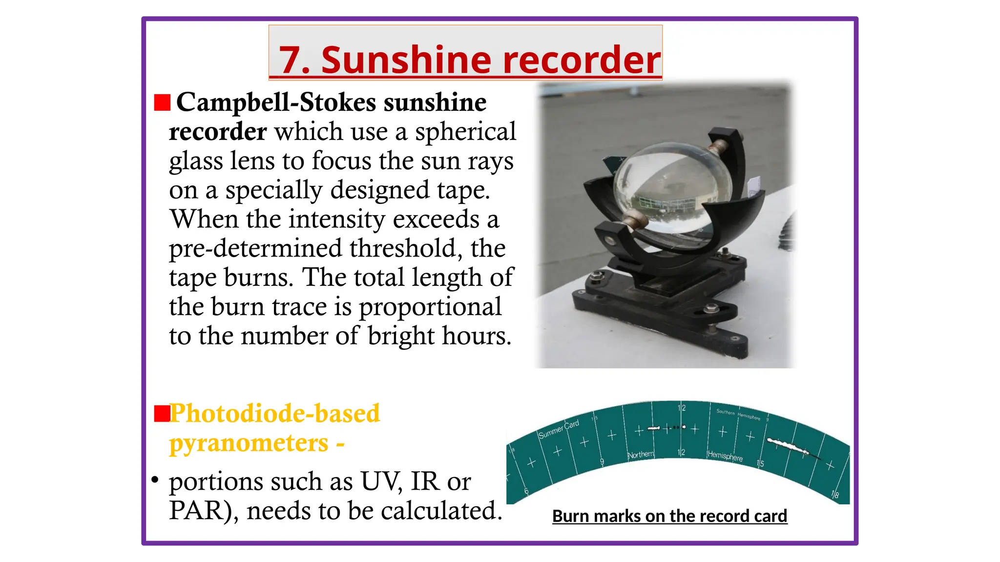
Campbell-Stokes sunshine
recorder whichuse a spherical
glass lens to focus the sun rays
on a specially designed tape.
When the intensity exceeds a
pre-determined threshold, the
tape burns. The total length of
the burn trace is proportional
to the number of bright hours.
Photodiode-based
pyranometers -
• portions such as UV, IR or
PAR), needs to be calculated. Burn marks on the record card
7. Sunshine recorder
18.
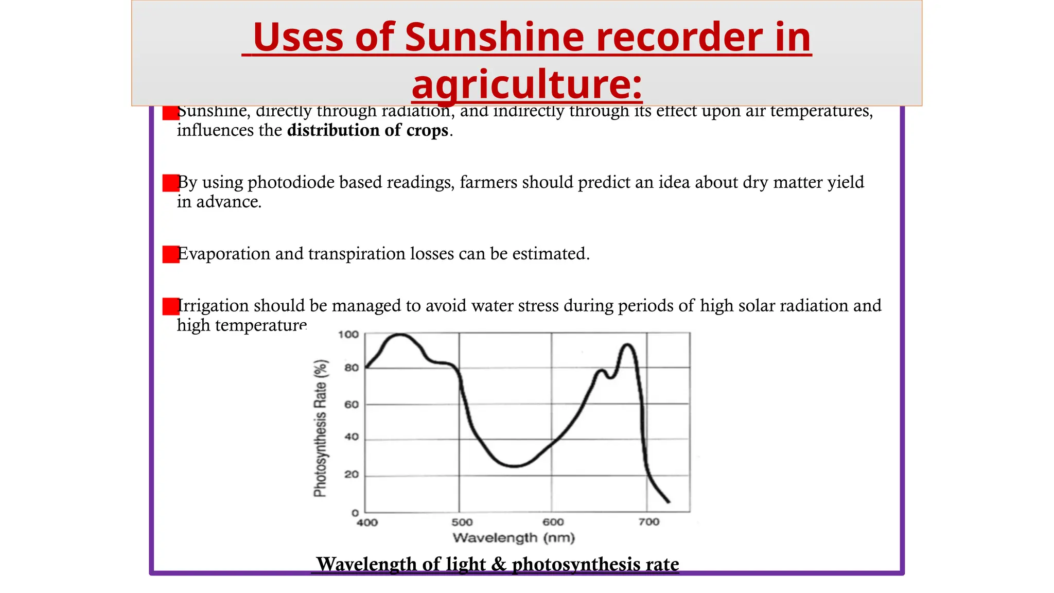
Sunshine, directly throughradiation, and indirectly through its effect upon air temperatures,
influences the distribution of crops.
By using photodiode based readings, farmers should predict an idea about dry matter yield
in advance.
Evaporation and transpiration losses can be estimated.
Irrigation should be managed to avoid water stress during periods of high solar radiation and
high temperature
Uses of Sunshine recorder in
agriculture:
Wavelength of light & photosynthesis rate
19.
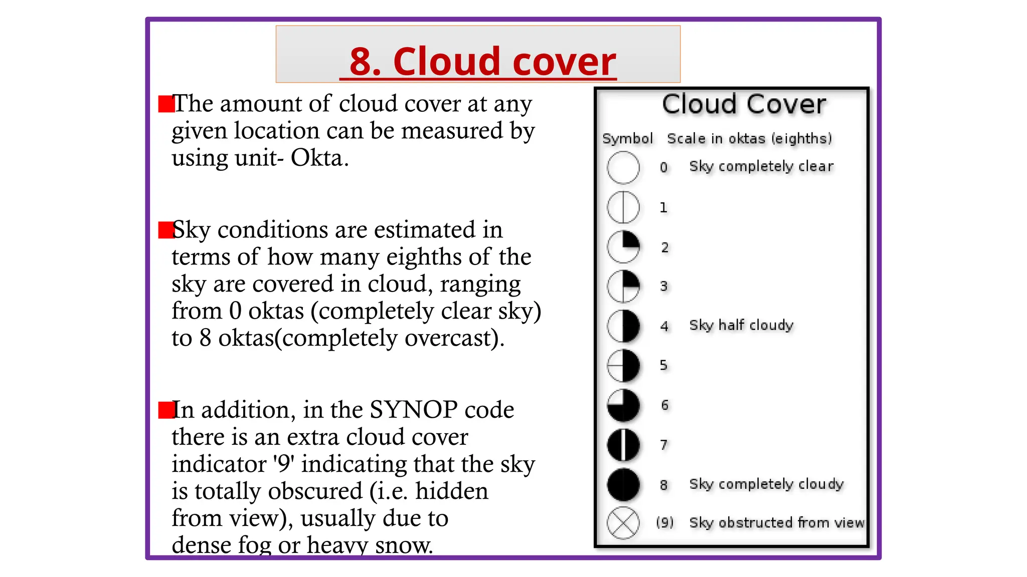
The amount ofcloud cover at any
given location can be measured by
using unit- Okta.
Sky conditions are estimated in
terms of how many eighths of the
sky are covered in cloud, ranging
from 0 oktas (completely clear sky)
to 8 oktas(completely overcast).
In addition, in the SYNOP code
there is an extra cloud cover
indicator '9' indicating that the sky
is totally obscured (i.e. hidden
from view), usually due to
dense fog or heavy snow.
8. Cloud cover
20.
• Cloud coverindirectly affects agriculture by affecting other
weather parameters, like-
Effect on evapotranspiration-
• Clear sky enhance the effect of solar radiation and hence ET.
Effect on Rainfall-
• The thicker clouds associated with heavier, but less frequent
rainfalls, gave average seasonal reductions of about 12 mm.
Effect on Solar radiation-
• complete cloud cover reduces the solar radiations, hence crop
growth and development.
Uses of Cloud cover in agriculture:
21.
Barometers are usedto measure the
current air pressure at a particular
location in "inches of mercury" or in
‘mill bars’ (mb). [29.92 inches of
mercury is equivalent to 1013.25 mb].
•
The commonly used barometer in
meteorological observatories is
Fortin’s barometer.
•
Barograph :Continuous recording of
pressure is made with this instrument.
9. Barometer
22.
Atmospheric pressure hasno direct influence on
crop growth. It is, however an important parameter in
weather forecasting.
Falling air pressure usually means that warmer,
moister air is coming, so there will be wet weather.
Low-pressure systems are associated with
cloudy, rainy, or windy weather.
Rising air pressure usually means that cooler, drier
air is coming, so there will be fair weather. A rapid
increase in atmospheric pressure pushes the cloudy
and rainy weather out, clearing the skies and bringing
in cool, dry air.
Uses of Barometer in agriculture:
23.
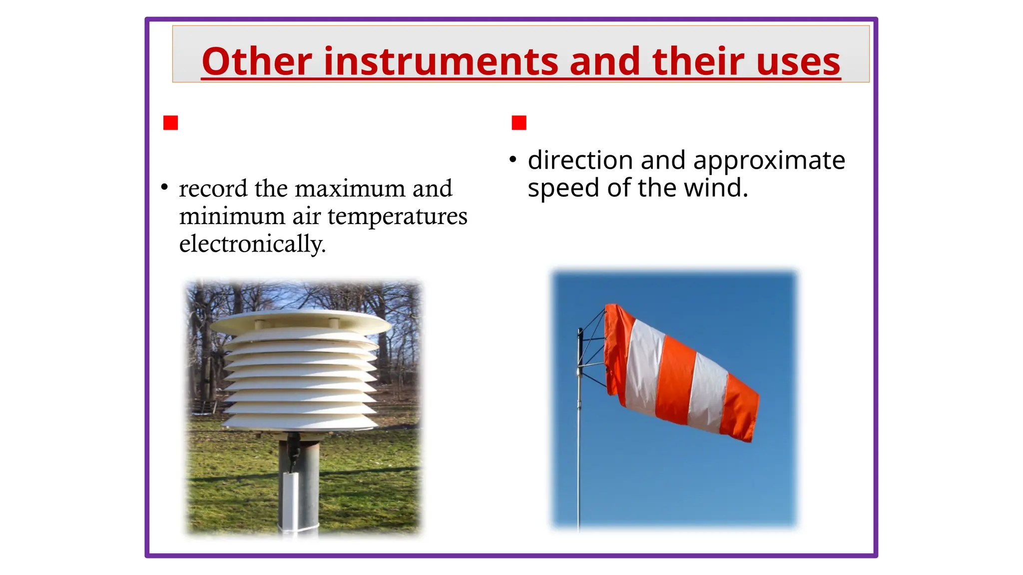
Max/Min Temperature
Sensor (MMTS):
•record the maximum and
minimum air temperatures
electronically.
Wind sock:
• direction and approximate
speed of the wind.
Other instruments and their uses
24.
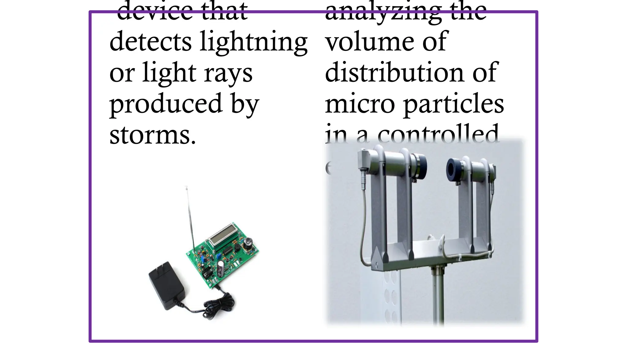
device that
detects lightning
orlight rays
produced by
storms.
analyzing the
volume of
distribution of
micro particles
in a controlled
environment.
25.
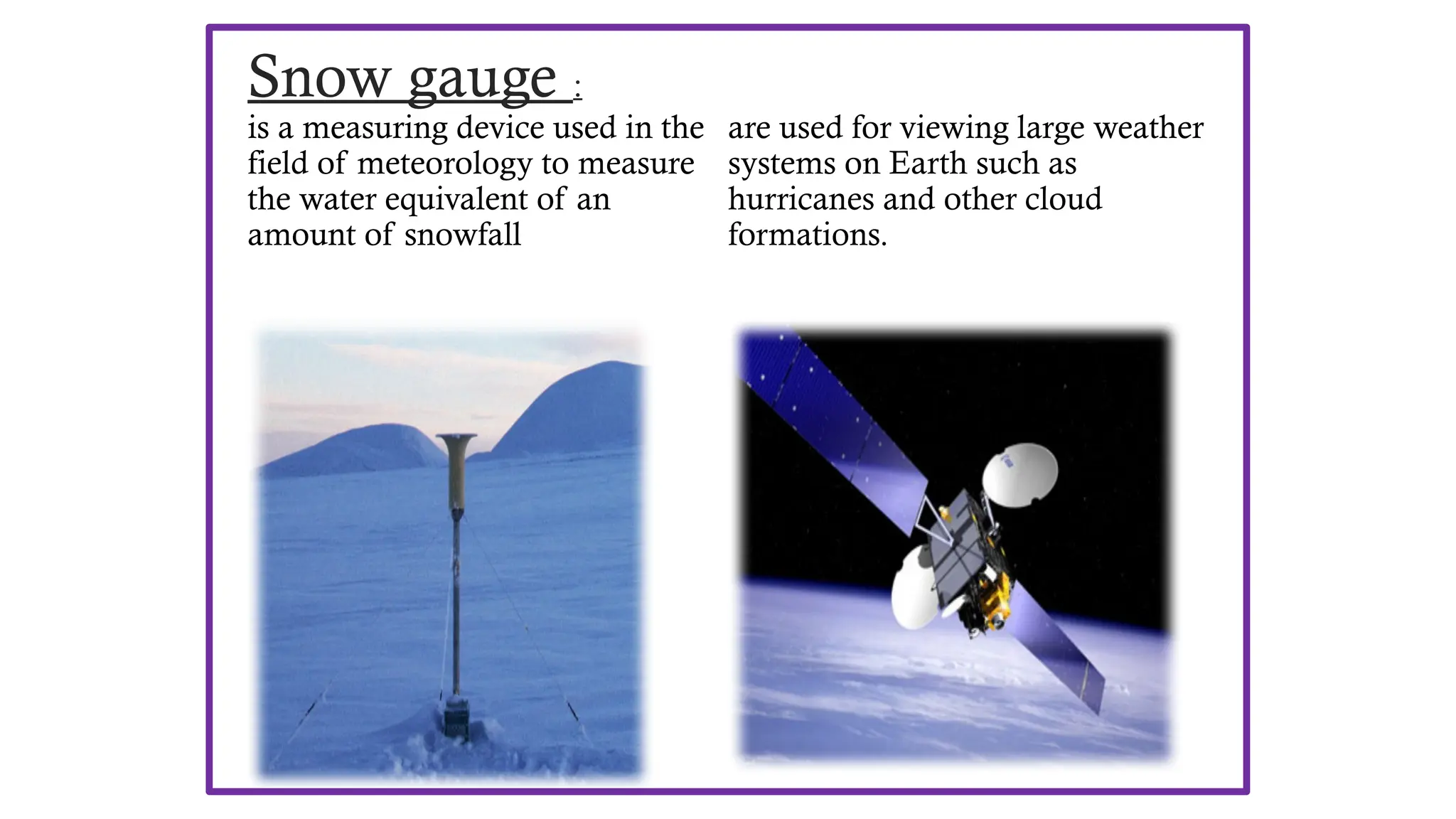
Snow gauge :
isa measuring device used in the
field of meteorology to measure
the water equivalent of an
amount of snowfall
Weather satellites :
are used for viewing large weather
systems on Earth such as
hurricanes and other cloud
formations.
27
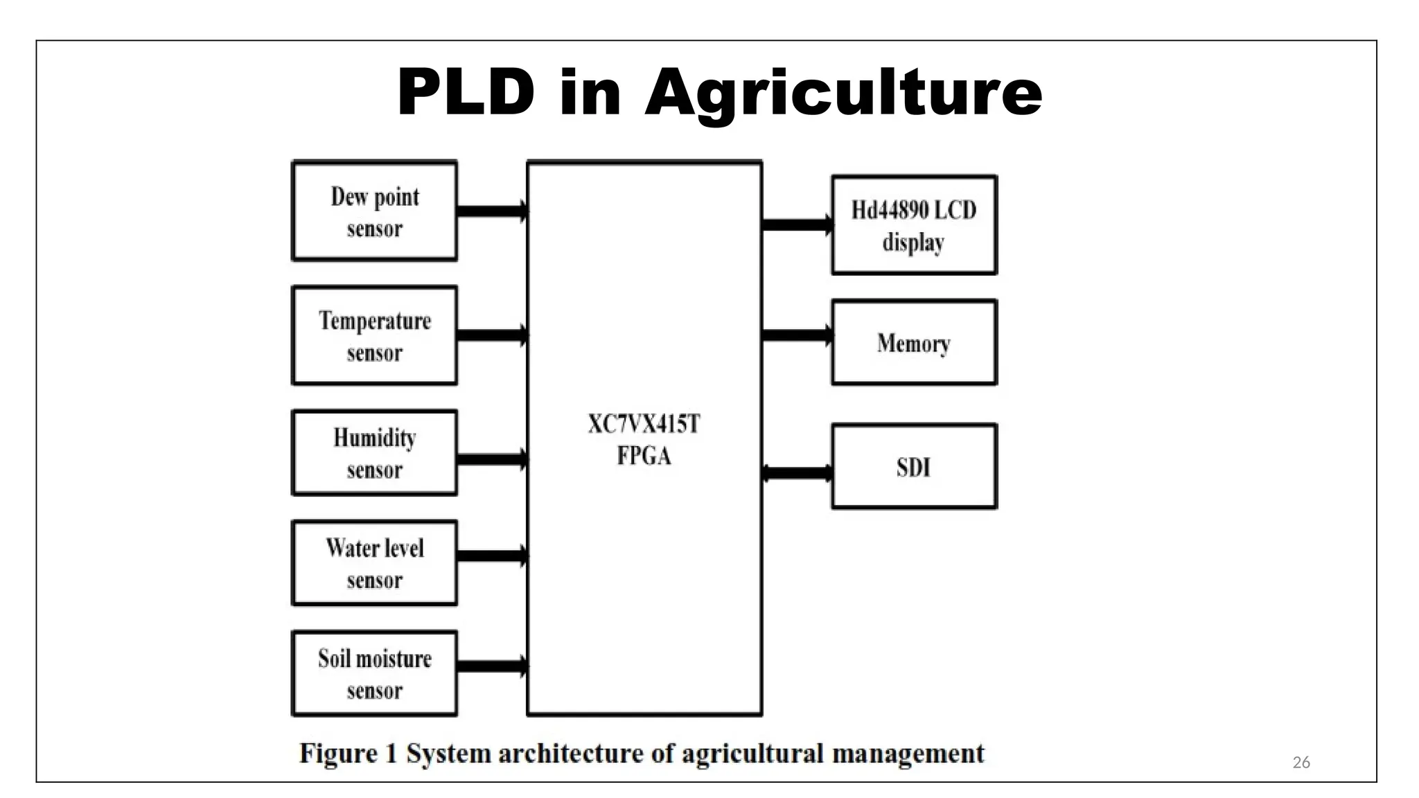
PLD in Agriculture
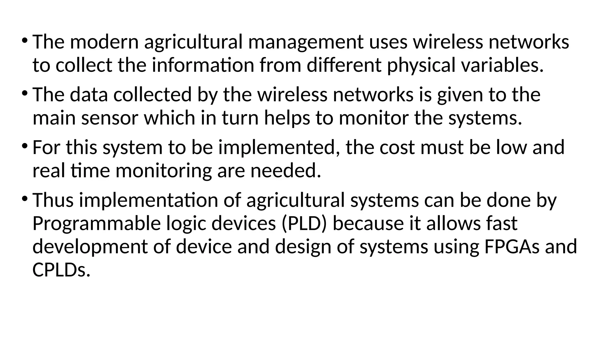
•The modern agricultural management uses wireless networks to
collect the information from different physical variables.
• The data collected by the wireless networks is given to the main
sensor which in turn helps to monitor the systems.
• For this system to be implemented, the cost must be low and real
time monitoring are needed.
• Thus implementation of agricultural systems can be done by
Programmable logic devices (PLD) because it allows fast development
of device and design of systems using FPGAs and CPLDs.
28.
28
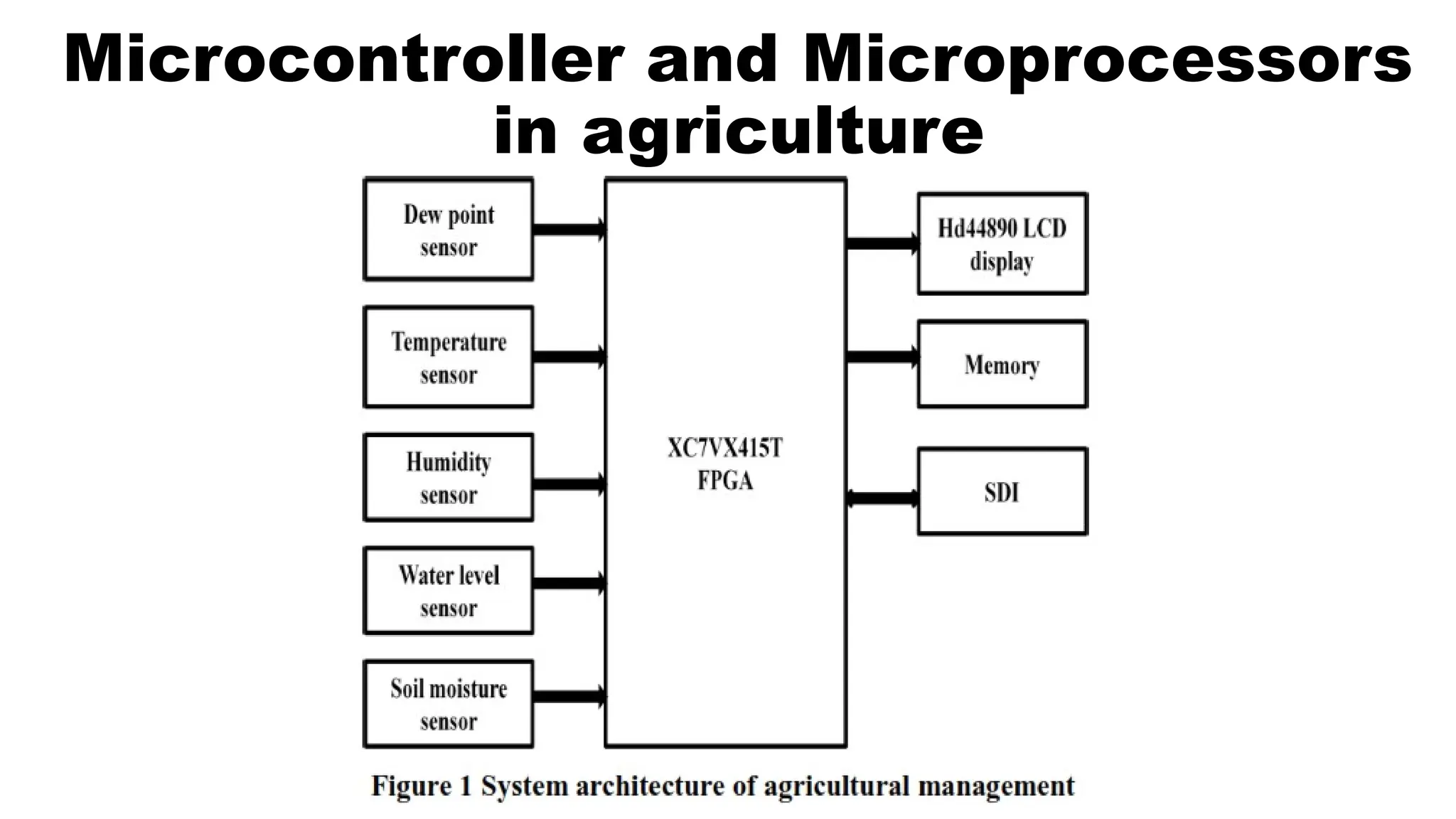
PLD in Agriculture
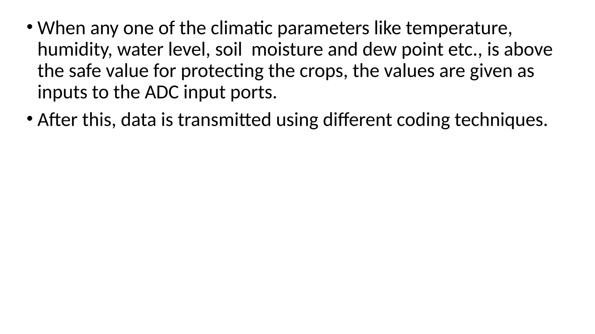
•When any one of the climatic parameters like temperature, humidity,
water level, soil moisture and dew point etc., is above the safe value
for protecting the crops, the values are given as inputs to the ADC
input ports.
• After this, data is transmitted using different coding techniques.
• The modernagricultural management uses wireless networks
to collect the information from different physical variables.
• The data collected by the wireless networks is given to the
main sensor which in turn helps to monitor the systems.
• For this system to be implemented, the cost must be low and
real time monitoring are needed.
• Thus implementation of agricultural systems can be done by
Programmable logic devices (PLD) because it allows fast
development of device and design of systems using FPGAs and
CPLDs.
31.
• When anyone of the climatic parameters like temperature,
humidity, water level, soil moisture and dew point etc., is above
the safe value for protecting the crops, the values are given as
inputs to the ADC input ports.
• After this, data is transmitted using different coding techniques.
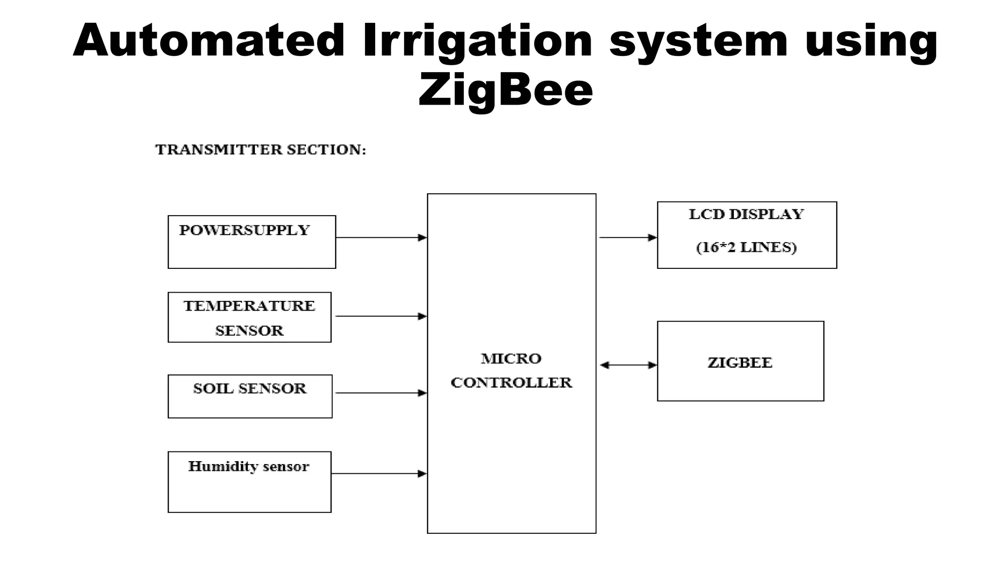
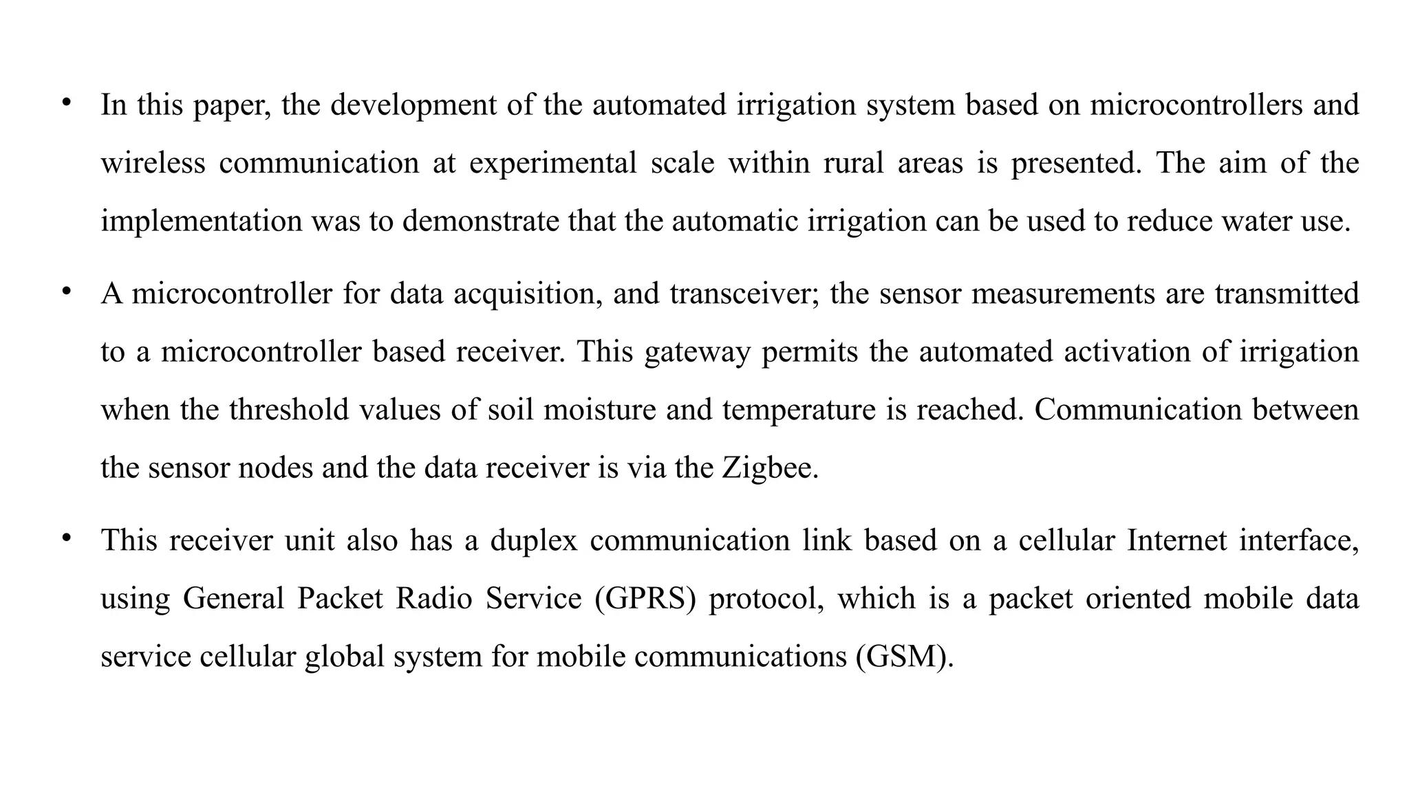
• In thispaper, the development of the automated irrigation system based on microcontrollers and
wireless communication at experimental scale within rural areas is presented. The aim of the
implementation was to demonstrate that the automatic irrigation can be used to reduce water use.
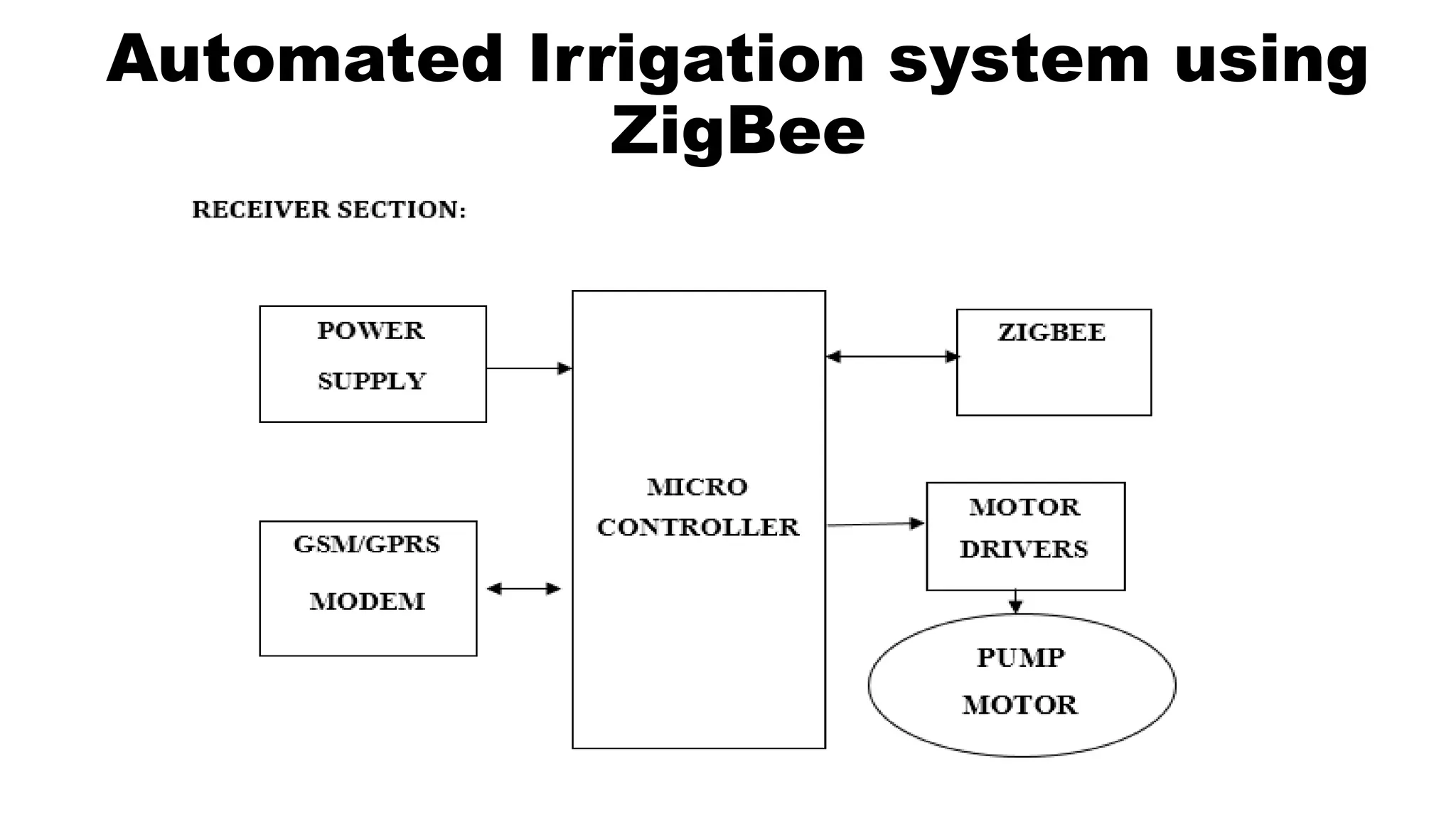
• A microcontroller for data acquisition, and transceiver; the sensor measurements are transmitted
to a microcontroller based receiver. This gateway permits the automated activation of irrigation
when the threshold values of soil moisture and temperature is reached. Communication between
the sensor nodes and the data receiver is via the Zigbee.
• This receiver unit also has a duplex communication link based on a cellular Internet interface,
using General Packet Radio Service (GPRS) protocol, which is a packet oriented mobile data
service cellular global system for mobile communications (GSM).
35.
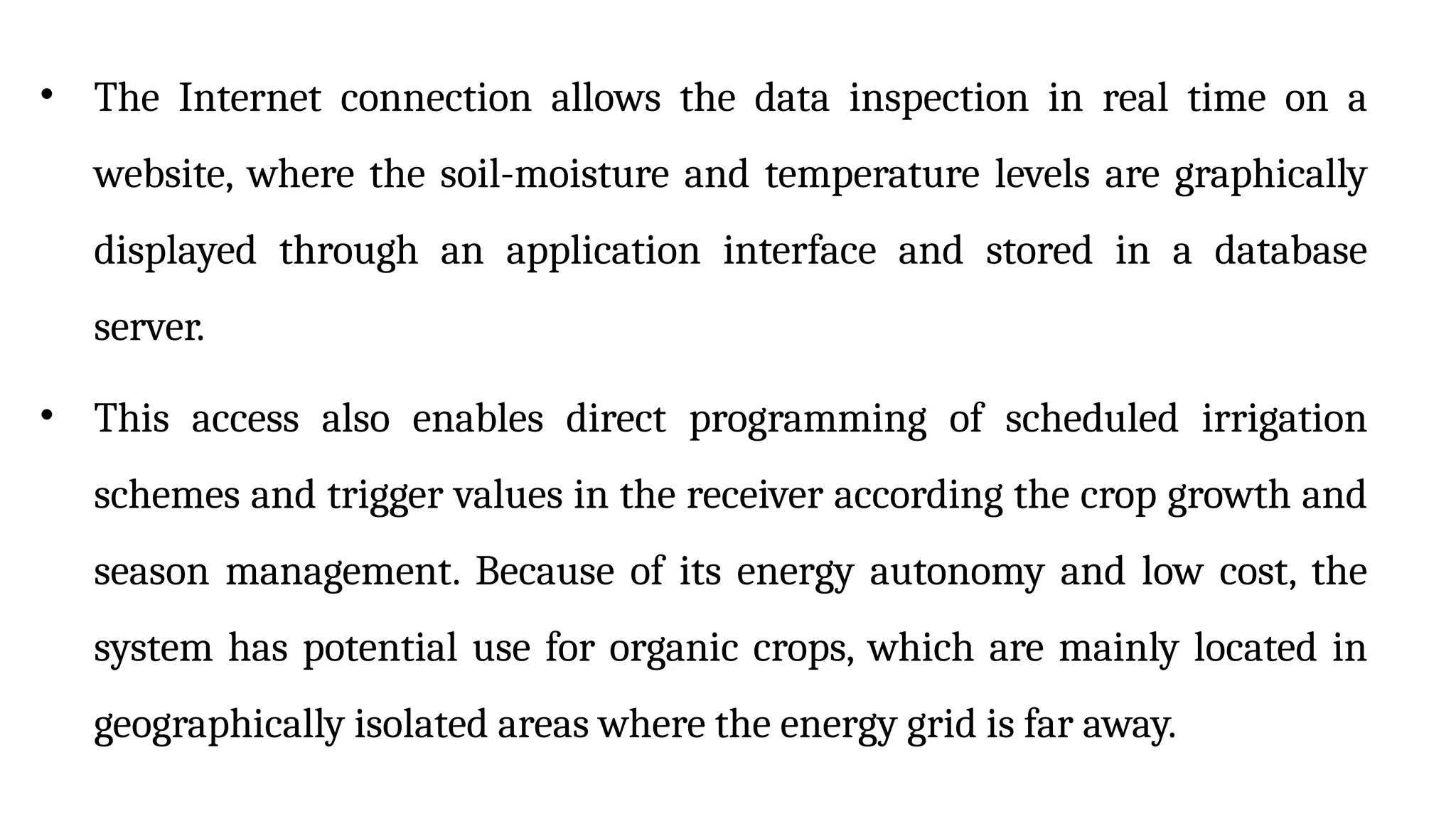
• The Internetconnection allows the data inspection in real time on a
website, where the soil-moisture and temperature levels are graphically
displayed through an application interface and stored in a database
server.
• This access also enables direct programming of scheduled irrigation
schemes and trigger values in the receiver according the crop growth and
season management. Because of its energy autonomy and low cost, the
system has potential use for organic crops, which are mainly located in
geographically isolated areas where the energy grid is far away.
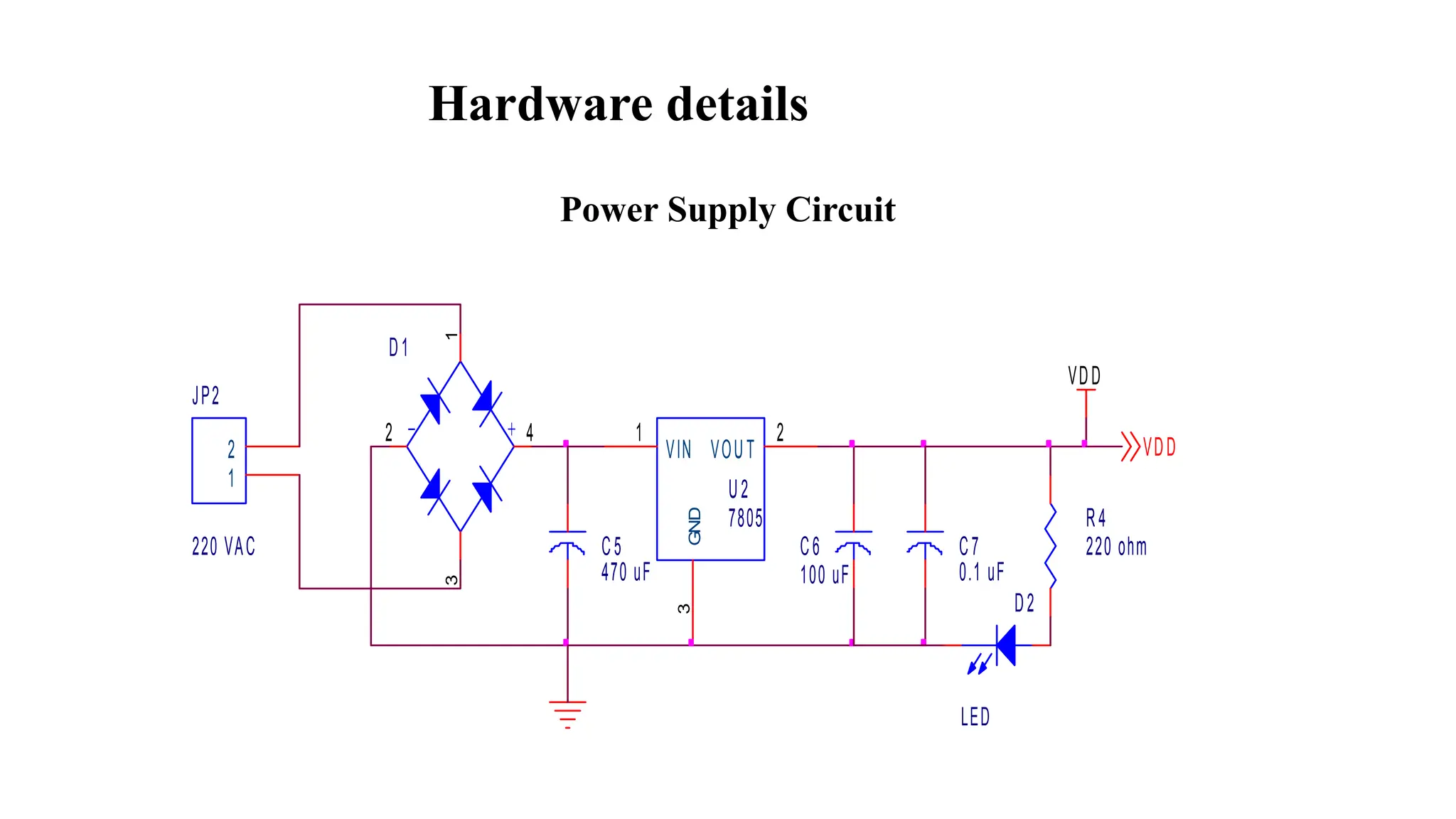
Power Supply –Circuit Description
• The operation of power supply circuits built using filters,
rectifiers, and then voltage regulators. Starting with an AC
voltage, a steady DC voltage is obtained by rectifying the AC
voltage,
• Then filtering to a DC level, and finally, regulating to obtain a
desired fixed DC voltage.
• The regulation is usually obtained from an IC voltage regulator
Unit, which takes a DC voltage and provides a somewhat lower
DC voltage, Which remains the same even if the input DC
voltage varies, or the output Load connected to the DC voltage
changes.
38.
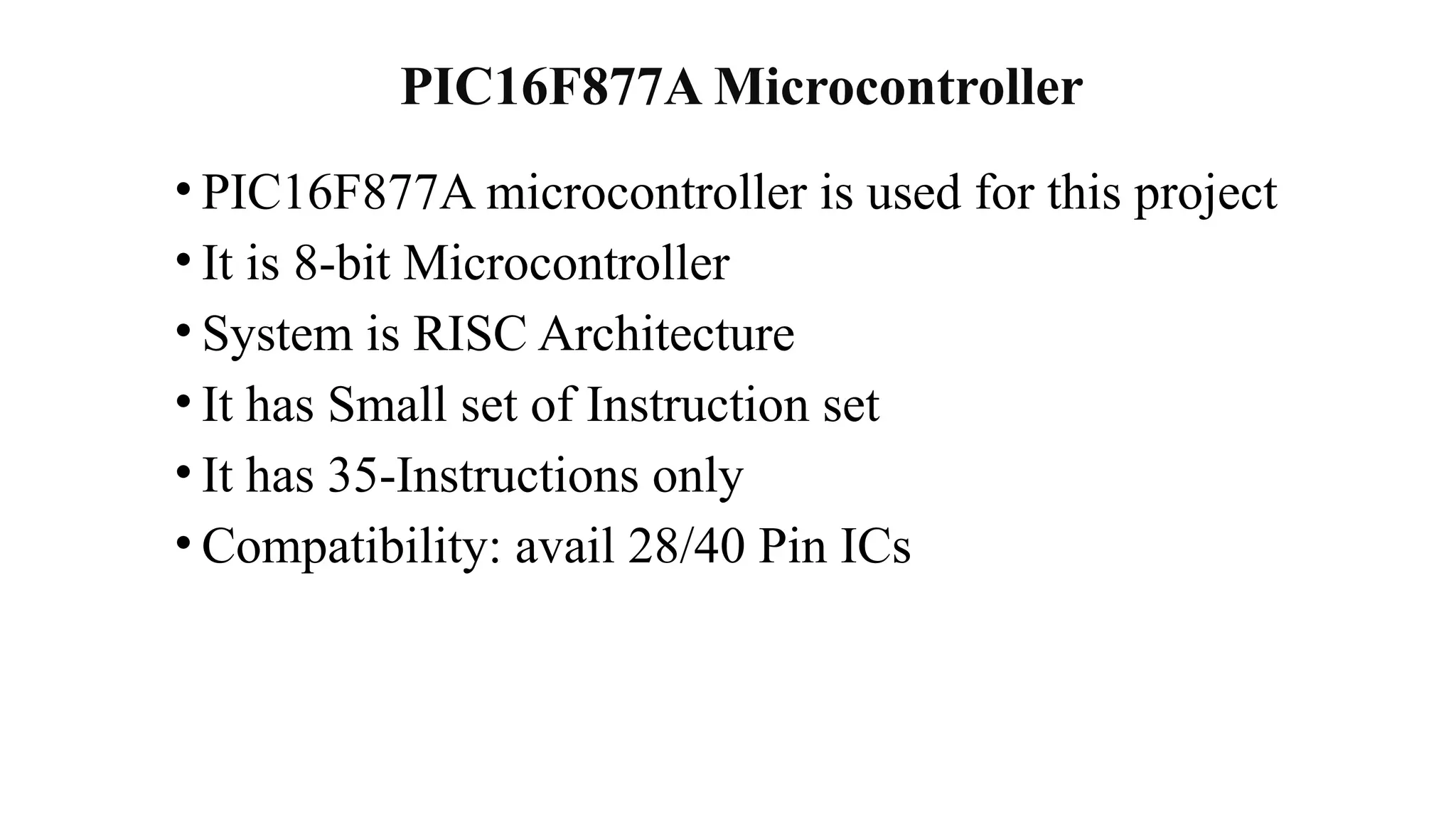
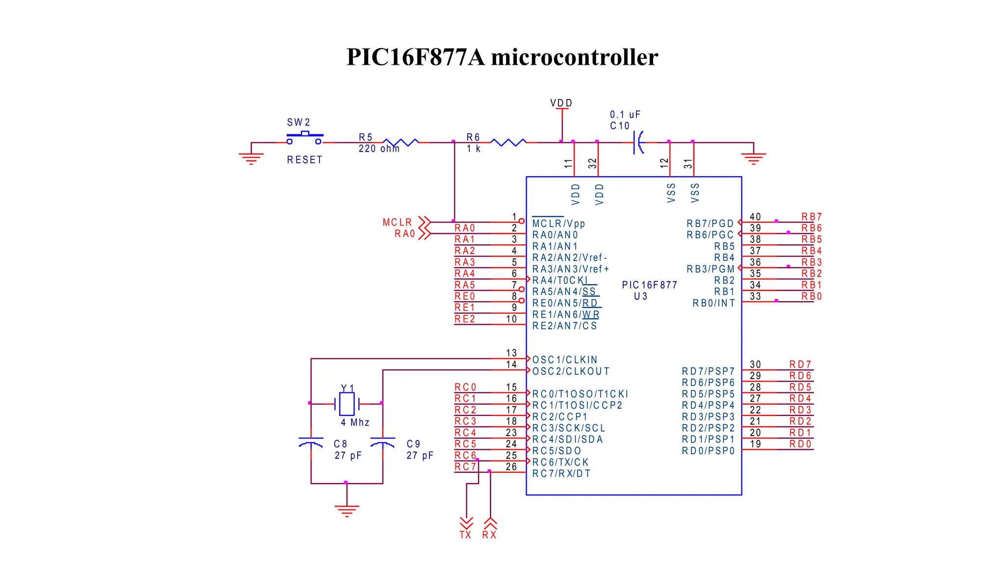
PIC16F877A Microcontroller
• PIC16F877Amicrocontroller is used for this project
• It is 8-bit Microcontroller
• System is RISC Architecture
• It has Small set of Instruction set
• It has 35-Instructions only
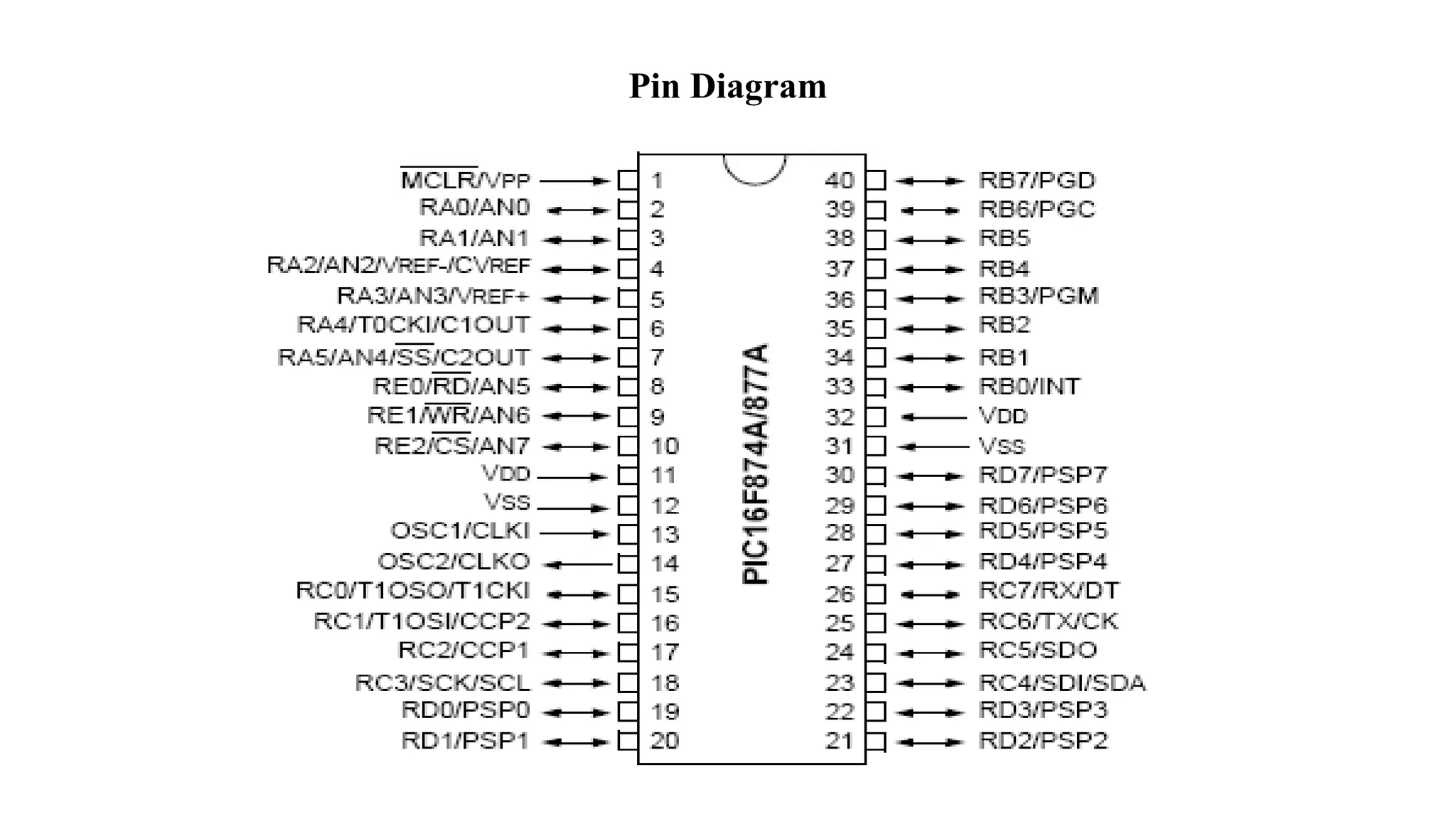
• Compatibility: avail 28/40 Pin ICs
39.
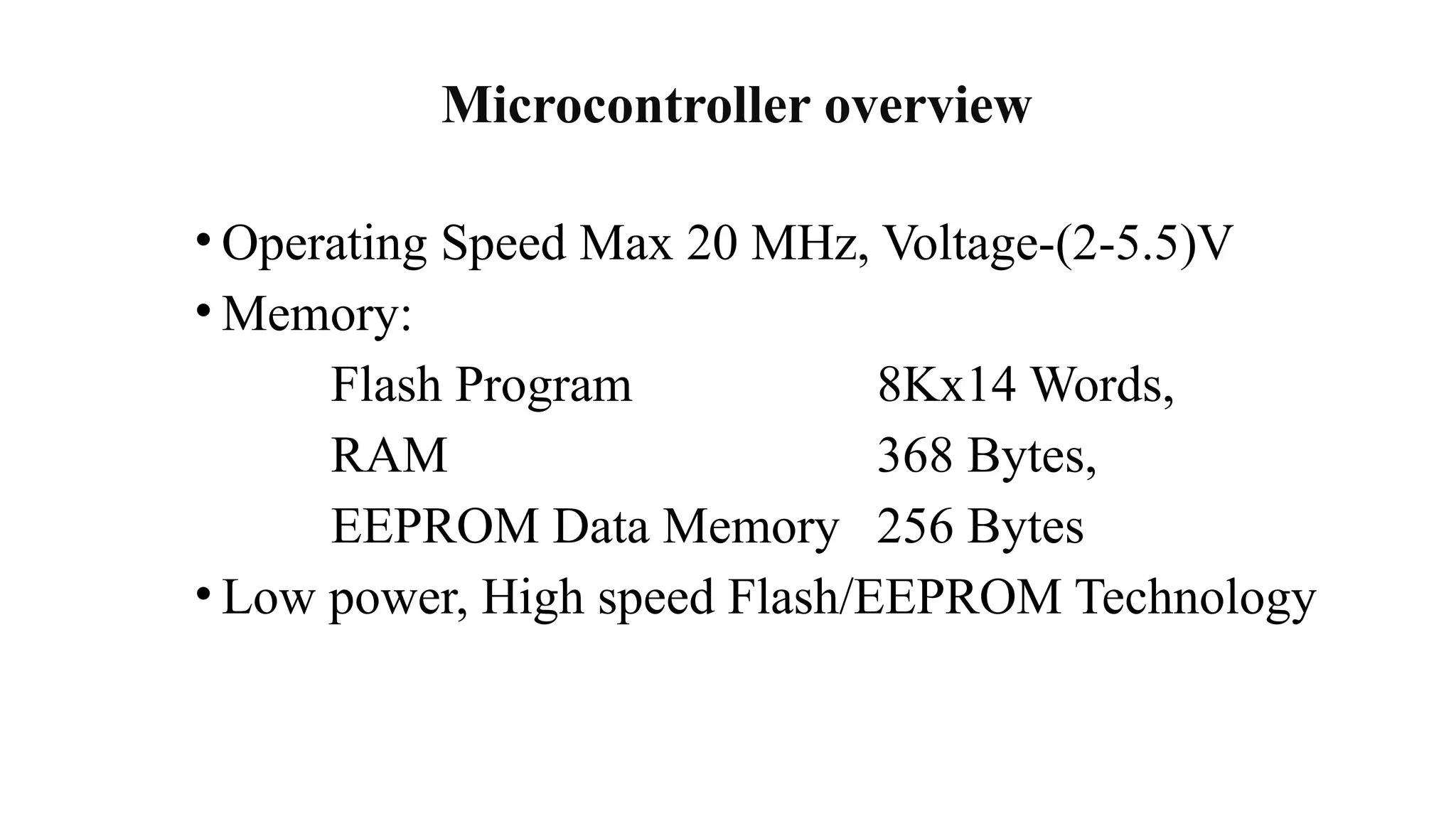
Microcontroller overview
• OperatingSpeed Max 20 MHz, Voltage-(2-5.5)V
• Memory:
Flash Program 8Kx14 Words,
RAM 368 Bytes,
EEPROM Data Memory 256 Bytes
• Low power, High speed Flash/EEPROM Technology
40.
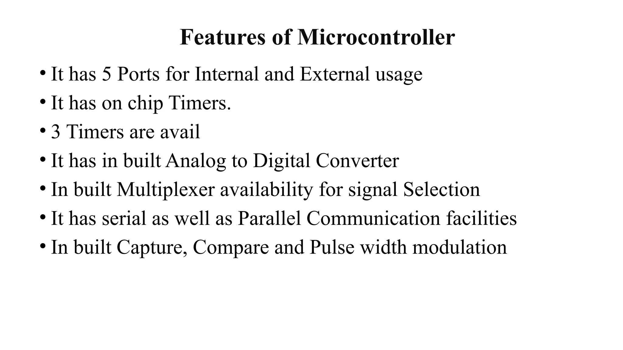
Features of Microcontroller
•It has 5 Ports for Internal and External usage
• It has on chip Timers.
• 3 Timers are avail
• It has in built Analog to Digital Converter
• In built Multiplexer availability for signal Selection
• It has serial as well as Parallel Communication facilities
• In built Capture, Compare and Pulse width modulation
PIC16F877A microcontroller
VD D
MCLR
R X
TX
R A0
R B7
R B6
R B5
R B4
R B3
R B2
R B1
R B0
R D 7
R D 6
R D 5
R D 4
R D 3
R D 2
R D 1
R D 0
R C 2
R C 3
R C 4
R C 5
R C 6
R C 7
R E 2
R E 1
R E 0
R A 5
R A 4
R A 3
R A 2
R A 1
R C 0
R C 1
R A 0
C 9
27 pF
C 8
27 pF
C 10
0.1 uF
P IC 16F 877
U 3
1
2
3
4
5
6
1
1
3
2
1
2
3
1
7
8
9
10
13
14
15
16
17
18
19
20
33
34
35
36
37
38
39
40
28
29
30
21
22
24
25
26
27
23
MC LR /V pp
R A 0/A N 0
R A 1/A N 1
R A 2/A N 2/Vref -
R A 3/A N 3/Vref +
R A 4/T0C K I
V
D
D
V
D
D
V
S
S
V
S
S
R A 5/A N 4/S S
R E 0/A N 5/R D
R E 1/A N 6/W R
R E 2/A N 7/C S
O S C 1/C LKIN
O S C 2/C LKO U T
R C 0/T1O S O /T1C K I
R C 1/T1O S I/C C P 2
R C 2/C C P 1
R C 3/S C K/SC L
R D 0/P SP 0
R D 1/P SP 1
R B0/IN T
R B1
R B2
R B3/P G M
R B4
R B5
R B6/P G C
R B7/P G D
R D 5/P SP 5
R D 6/P SP 6
R D 7/P SP 7
R D 2/P SP 2
R D 3/P SP 3
R C 5/S D O
R C 6/TX/C K
R C 7/R X/D T
R D 4/P SP 4
R C 4/S D I/S D A
Y 1
4 Mhz
R 6
1 k
R 5
220 ohm
S W 2
R ES ET
43.
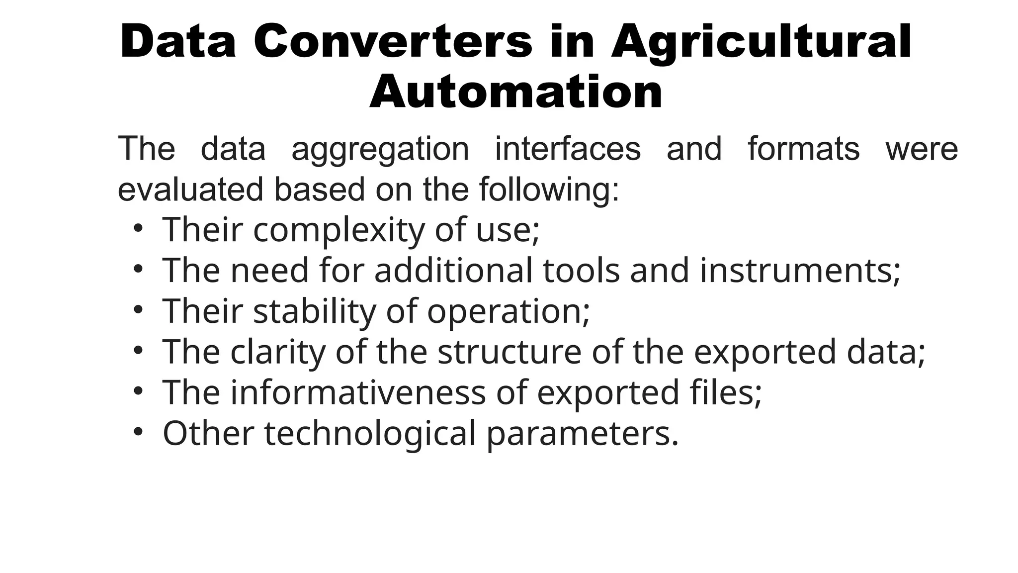
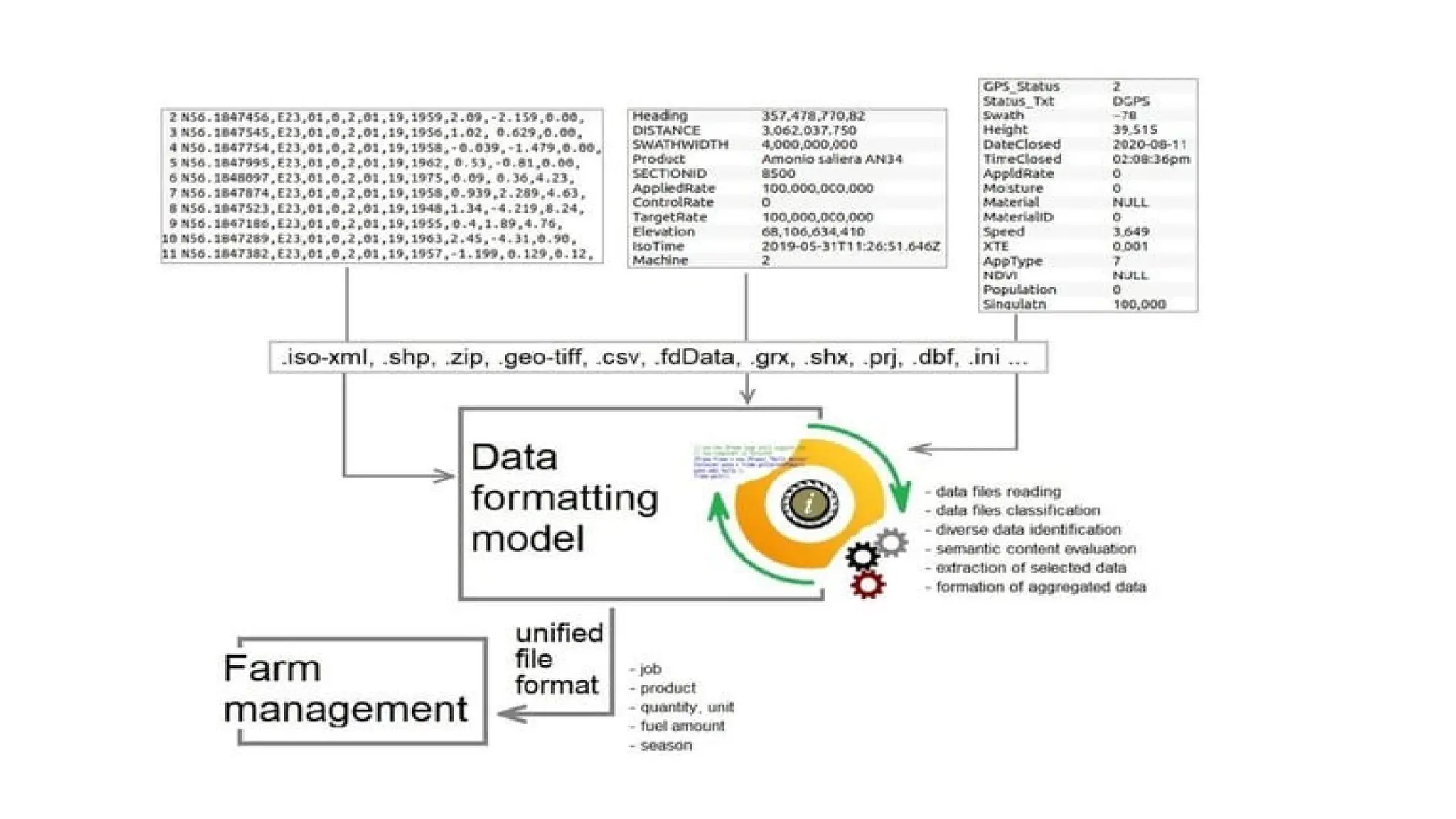
Data Converters inAgricultural
Automation
The data aggregation interfaces and formats were
evaluated based on the following:
• Their complexity of use;
• The need for additional tools and instruments;
• Their stability of operation;
• The clarity of the structure of the exported data;
• The informativeness of exported files;
• Other technological parameters.
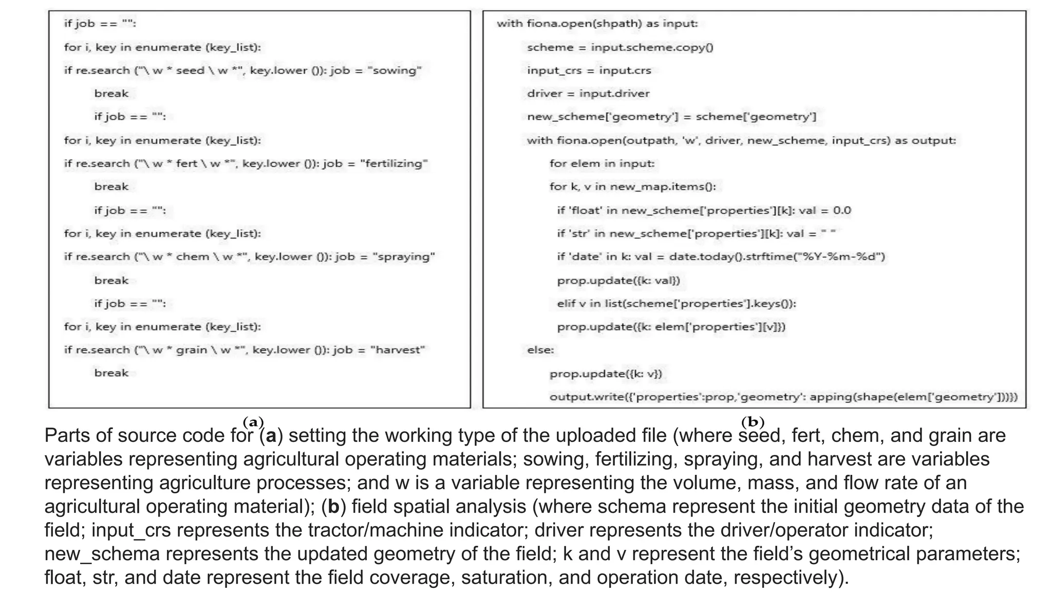
Parts of sourcecode for (a) setting the working type of the uploaded file (where seed, fert, chem, and grain are
variables representing agricultural operating materials; sowing, fertilizing, spraying, and harvest are variables
representing agriculture processes; and w is a variable representing the volume, mass, and flow rate of an
agricultural operating material); (b) field spatial analysis (where schema represent the initial geometry data of the
field; input_crs represents the tractor/machine indicator; driver represents the driver/operator indicator;
new_schema represents the updated geometry of the field; k and v represent the field’s geometrical parameters;
float, str, and date represent the field coverage, saturation, and operation date, respectively).
48.
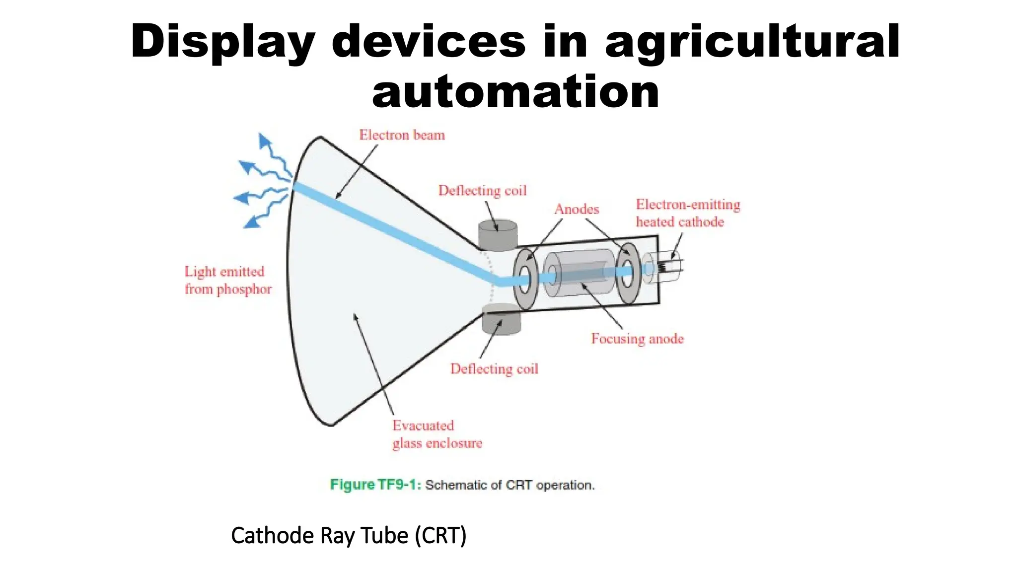
Cathode Ray Tube(CRT)
Display devices in agricultural
automation
49.
Cathode Ray Tube(CRT)
• In a CRT, an electron gun is placed behind a
positively charged glass screen, and a negatively charged electrode
(the cathode) is mounted at the input of the electron gun.
• During operation, the cathode emits streams of electrons into the
electron gun.
• The emitted electron stream is steered onto different
parts of the positively charged screen by the electron
gun; the direction of the electron stream is controlled
by the electric field of the deflecting coils through which the
beam passes.
50.
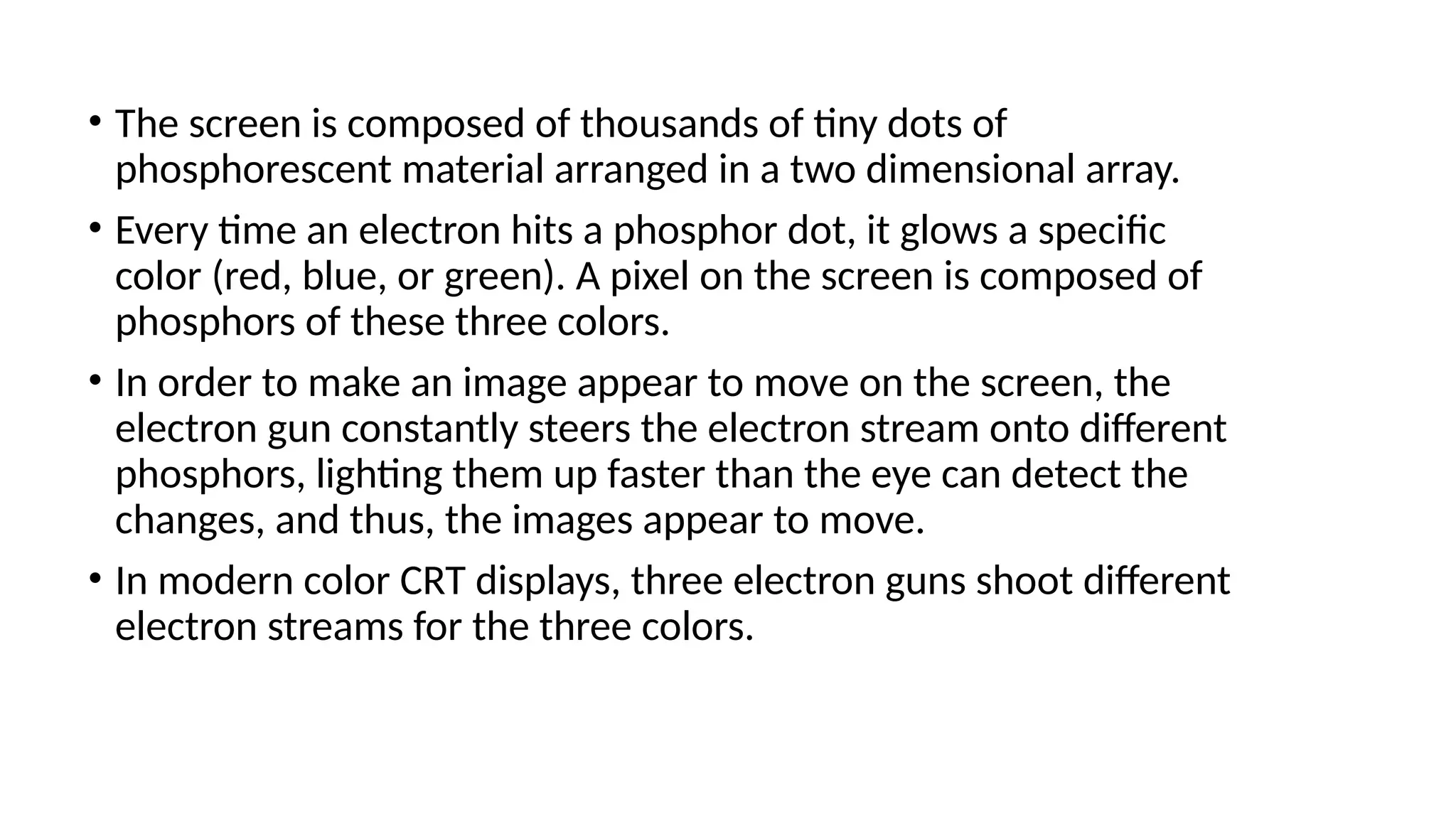
• The screenis composed of thousands of tiny dots of
phosphorescent material arranged in a two dimensional array.
• Every time an electron hits a phosphor dot, it glows a specific
color (red, blue, or green). A pixel on the screen is composed of
phosphors of these three colors.
• In order to make an image appear to move on the screen, the
electron gun constantly steers the electron stream onto different
phosphors, lighting them up faster than the eye can detect the
changes, and thus, the images appear to move.
• In modern color CRT displays, three electron guns shoot different
electron streams for the three colors.
51.
Liquid Crystal display(LCD)
• LCDs’ offer advantages over other technologies (such as cathode
ray tubes) in that they are lighter and thinner and consume a lot
less power to operate.
• LCD technology relies on special electrical and optical properties
of a class of materials known as liquid crystals, first discovered
in the 1880s
by botanist Friedrich Reinitzer.
• In the basic LCD display, light shines through a thin stack of layers
as shown in Figure.
53.
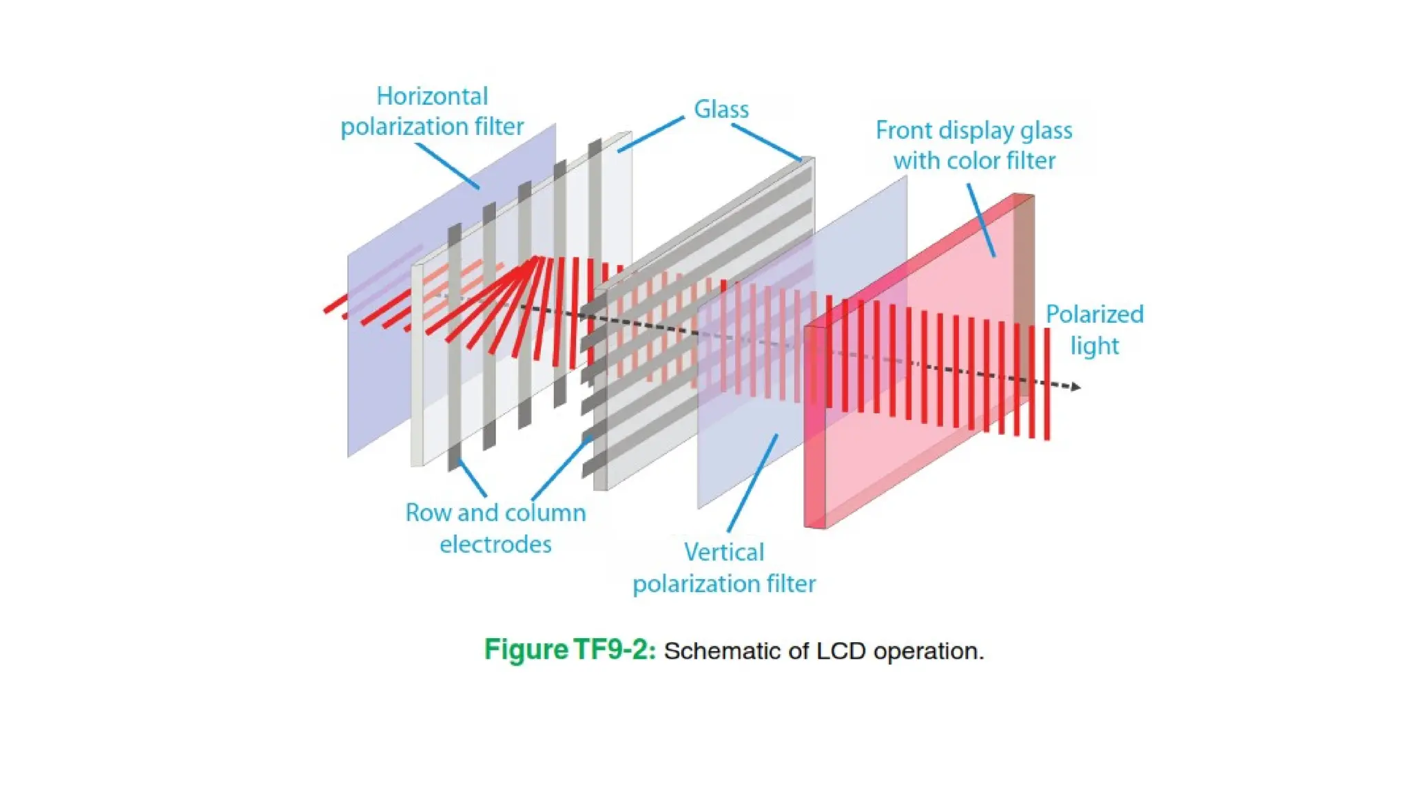
• Each stackconsists of layers in the following
• Order : color filter, vertical (or horizontal) polarizer filter, glass plate
with transparent electrodes, liquid crystal layer, second glass plate
with transparent electrodes, horizontal (or vertical) polarizer filter.
• Light is shone from behind the stack (called the backlight). As light
crosses through the layer stack, it is polarized along one direction
by the first filter.
54.
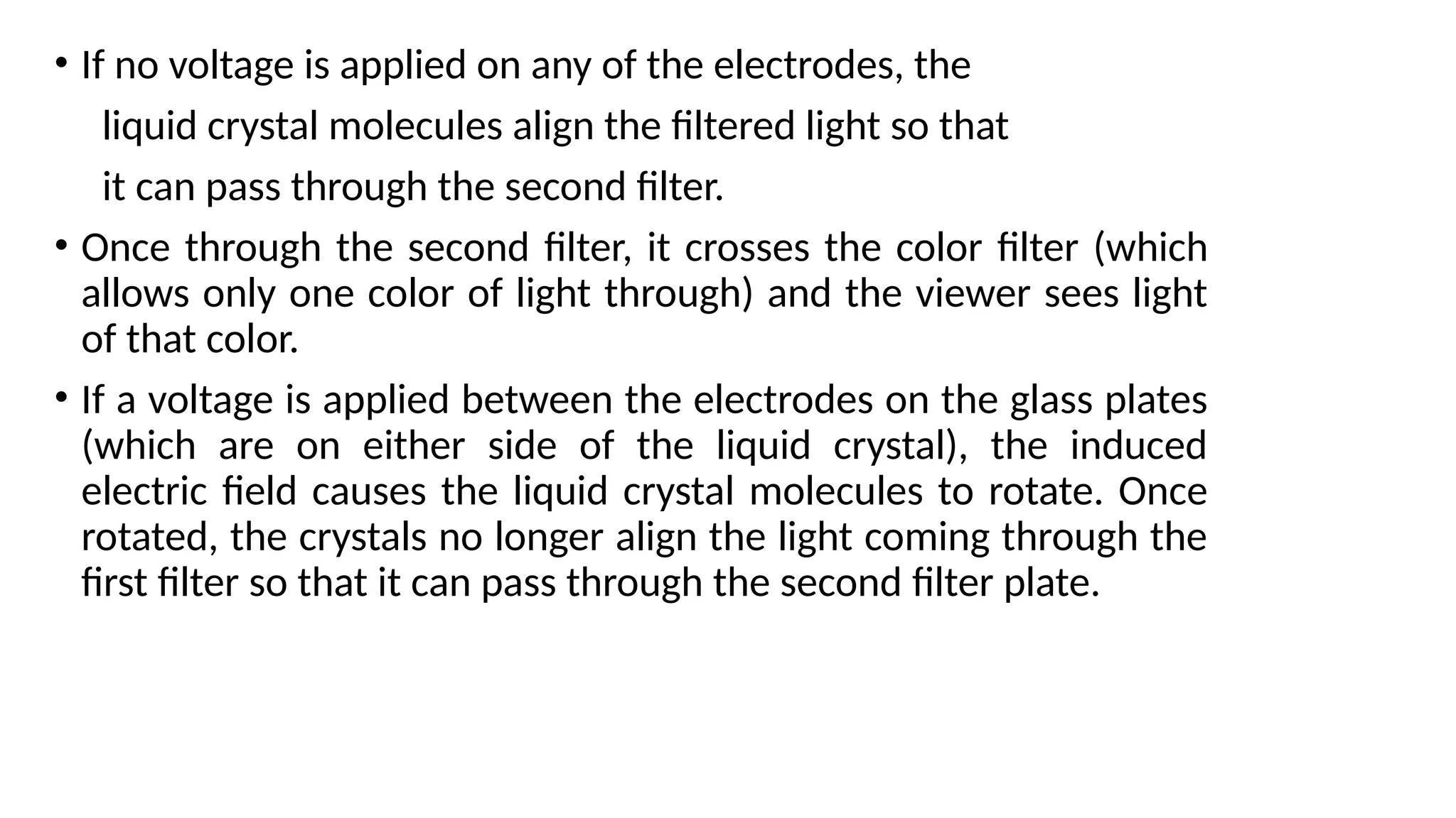
• If novoltage is applied on any of the electrodes, the
liquid crystal molecules align the filtered light so that
it can pass through the second filter.
• Once through the second filter, it crosses the color filter (which
allows only one color of light through) and the viewer sees light
of that color.
• If a voltage is applied between the electrodes on the glass plates
(which are on either side of the liquid crystal), the induced
electric field causes the liquid crystal molecules to rotate. Once
rotated, the crystals no longer align the light coming through the
first filter so that it can pass through the second filter plate.
55.
• If lightcannot cross, the area with the applied
voltage looks dark. This is precisely how simple hand-
held calculator displays work; usually the bright
background is made dark every time a character is
displayed.
56.
Thin-Film Transistor (TFT)(version of LCD)
• They are also called active matrix displays. In TFT
LCDs, several thin films are deposited on one of the
glass substrates and patterned into transistors.
• Each color component of a pixel has its own
microscale transistor that controls the voltage across
the liquid crystal; since the transistors only take up a
tiny portion of the pixel area, they effectively are
invisible.
• Thus, each pixel has its own electrode driver built
directly into it. This specific feature enabled the
construction of the flat high-resolution screens in
common use.
57.
Light Emitting Diode(LED) displays
• A different but very popular display technology employs
tiny light-emitting diodes (LED) in large pixel arrays on flat
screens.
• Each pixel in an LED display is composed of three LEDs
(one each of red, green, and blue). Whenever a current is
made to pass through a particular LED, it emits light at its
particular color.
• In this way, displays can be made flatter (i.e., the LED
circuitry takes up less room than an electron gun or LCD)
and larger (since making large, flat LED arrays technically
is less challenging than giant CRT tubes or LCD displays).
• Unlike LCDs, LED displays do not need a backlight to
function and easily can be made multicolor.
58.
Organic LEDs (OLED)
•Modern LED research is focused mostly on flexible
and organic LEDs (OLEDs), which are made from
polymer light-emitting materials and can be
fabricated on flexible substrates (such as an overhead
transparency).
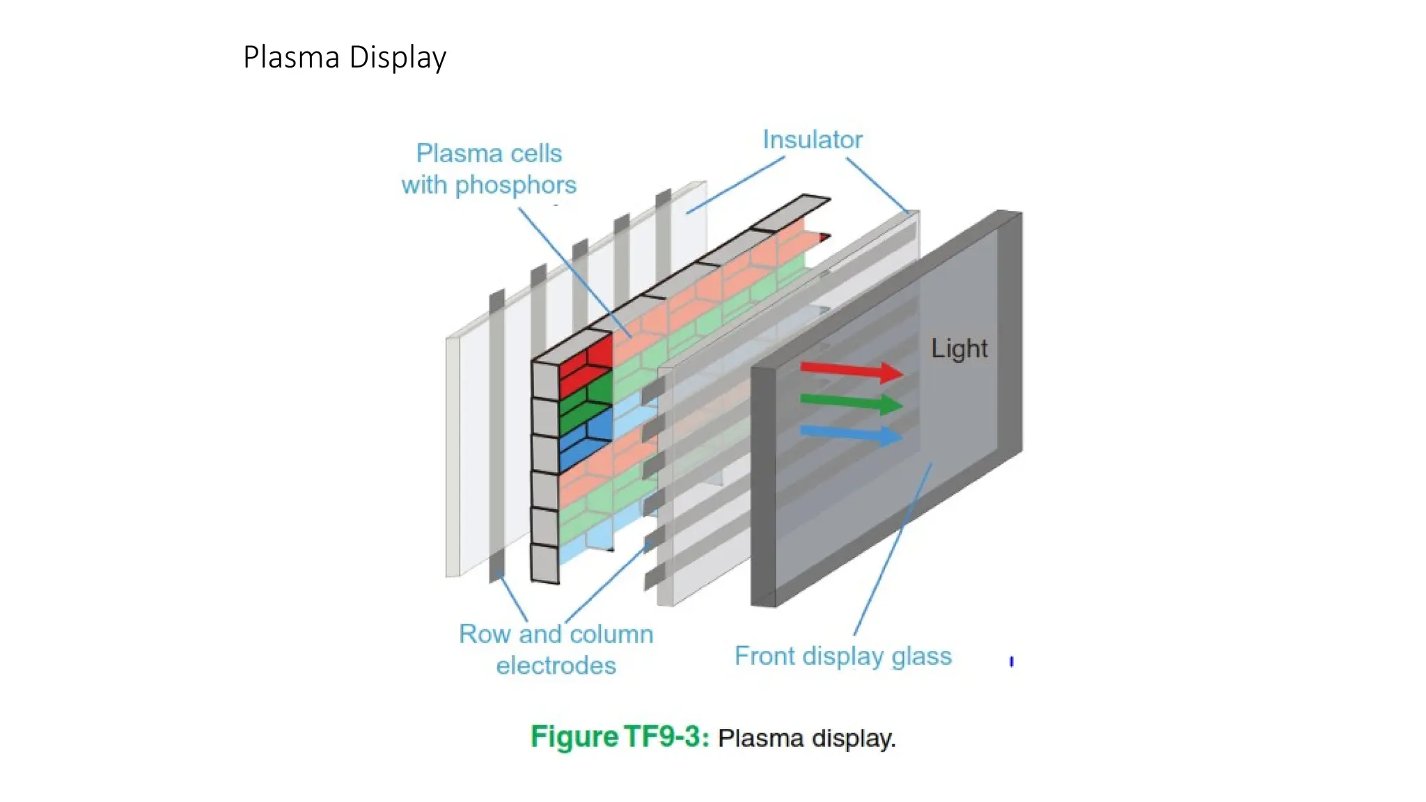
Plasma display
• Eachpixel in a plasma display contains one or more
microscale pocket(s) of trapped noble gas (usually neon
or xenon); electrodes patterned on a glass substrate
are placed in front and behind each pocket of gas
• The back of one of the glass plates is coated with light-
emitting phosphors. When a sufficient voltage is
applied across the electrodes, a large electric field is
generated across the noble gas, and a plasma (ionized
gas) is ignited.
• The plasma emits ultraviolet light which impacts the
phosphors; when impacted with UV light, the
phosphors emit light of a certain color (blue, green, or
red). In this way, each pocket can generate one color.
• Optoelectronics isthe communication between optics
and electronics which includes the study, design and
manufacture of a hardware device that
converts electrical energy into light and light into energy
through semiconductors.
• Optoelectronics device is basically an electronic device
involving light.
• This device can be found in many optoelectronics
applications in agriculture automation
64.
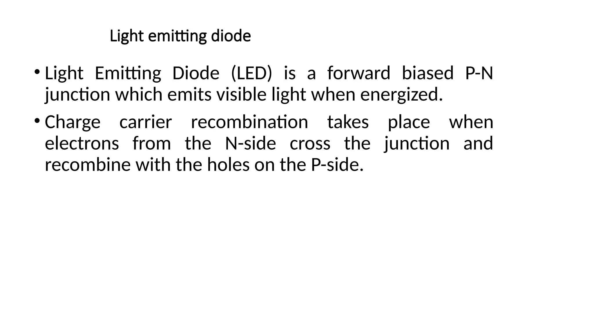
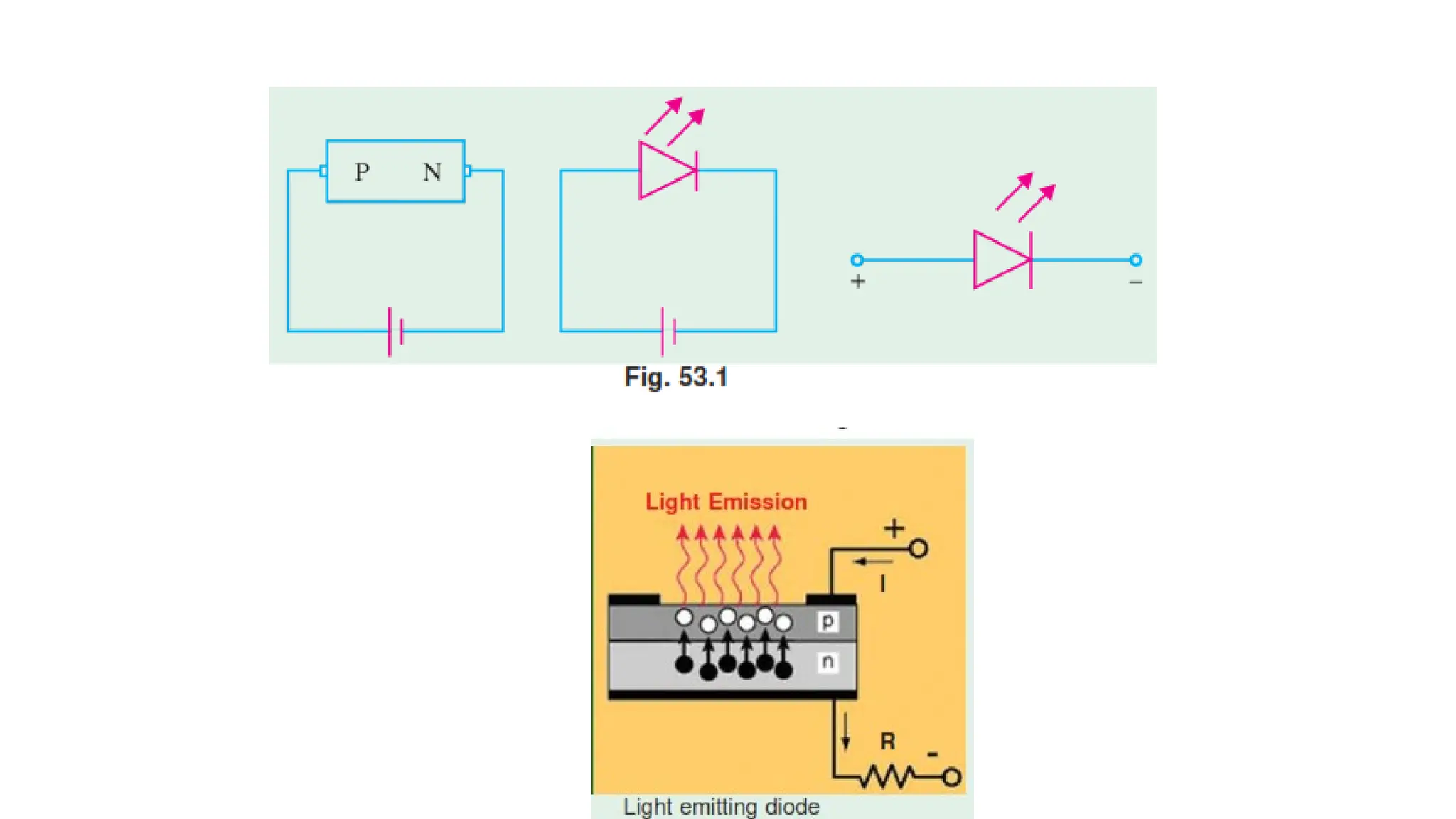
Light emitting diode
•Light Emitting Diode (LED) is a forward biased P-N
junction which emits visible light when energized.
• Charge carrier recombination takes place when
electrons from the N-side cross the junction and
recombine with the holes on the P-side.
66.
• Electrons arein the higher conduction band on the N- side
whereas holes are in the lower valence band on the P-side.
• During recombination, some of the energy difference is
given in the form of heat and light (i.e. photons).
• For Si and Ge junctions, greater percentage of this energy is
given up in the form of heat.
• But in semiconductor materials like Galllium Arsenide
(GaAs) and Gallium Phosphide (GaP), a greater percentage
of energy released during recombination is given in the
form of light.
67.
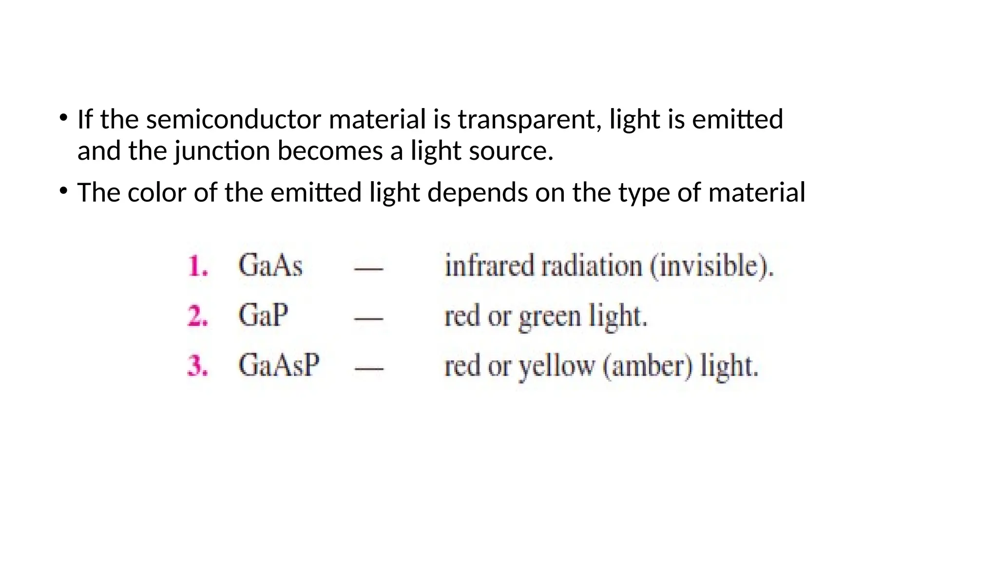
• If thesemiconductor material is transparent, light is emitted
and the junction becomes a light source.
• The color of the emitted light depends on the type of material
68.
Photoconductive cell
•It isa semiconductor device whose resistance varies
inversely with the intensity of light that falls upon it.
•It is also called photoresistive cell or photoresistor.
•The resistivity of semiconductor depends on the
number of free charge carriers available in it.
•When the semiconductor is not illuminated, the
number of charge carriers is small and hence resistivity
is high.
• Precision Agriculture– Helps in applying the inputs optimally and
minimize the degradation of soil and environment
• The field water efficiency in the farmer’s field is hardly 40% to
50%
• Adaption of suitable surface irrigation methods can raise this
efficiency considerably
• Excess or deficit of water in soil will adversely affect the
productivity.
71.
• Drip irrigationaims at supplying water and nutrients directly to the plant
roots. It aims at using the water according to the plant needs.
• As water resources become more limited due to competition from
residential and industrial uses, it is becoming more important to increase
plant production water usage efficiency
• Prevention of over watering improve water usage efficiency and pest
prevention (reduces root zone diseases such as Pythium)
73.
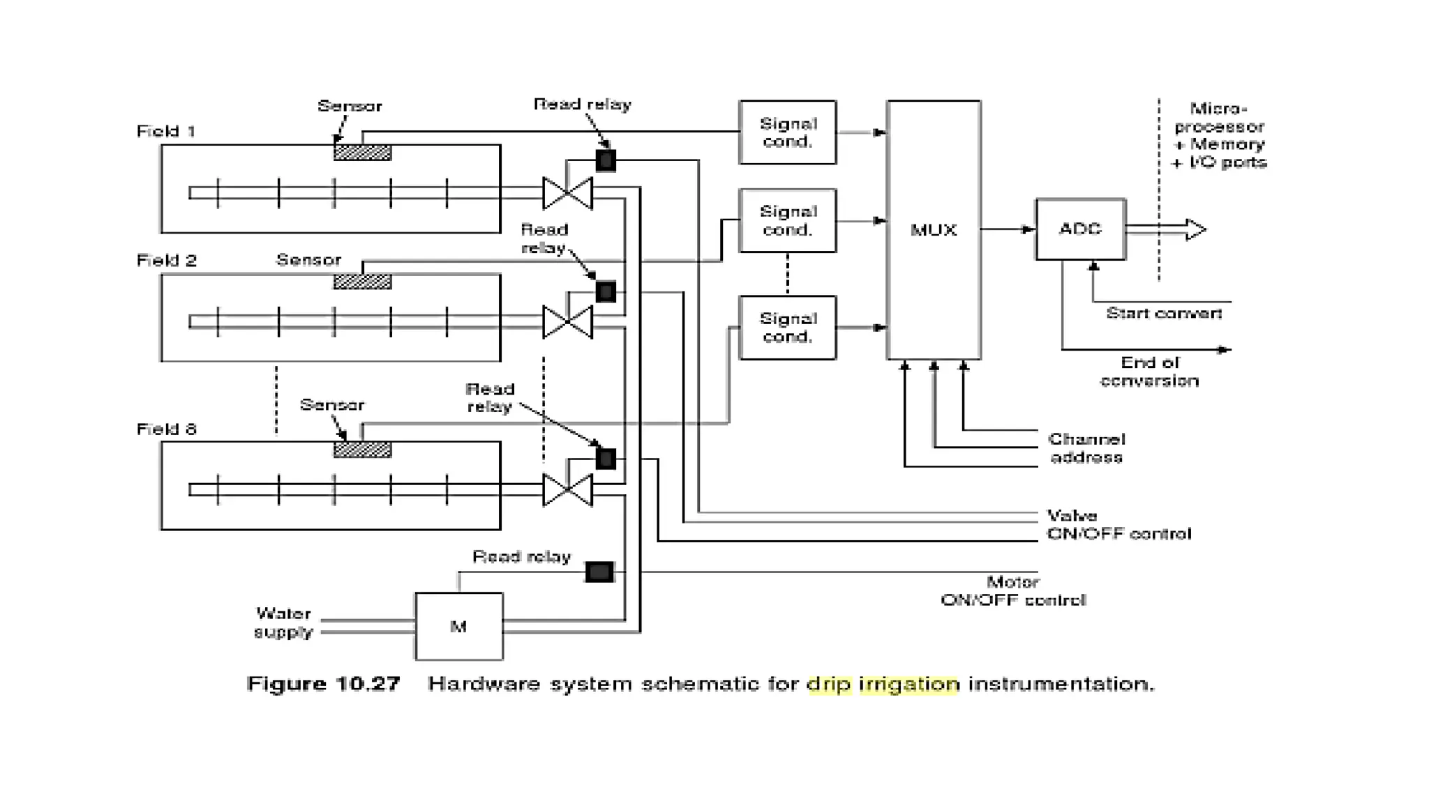
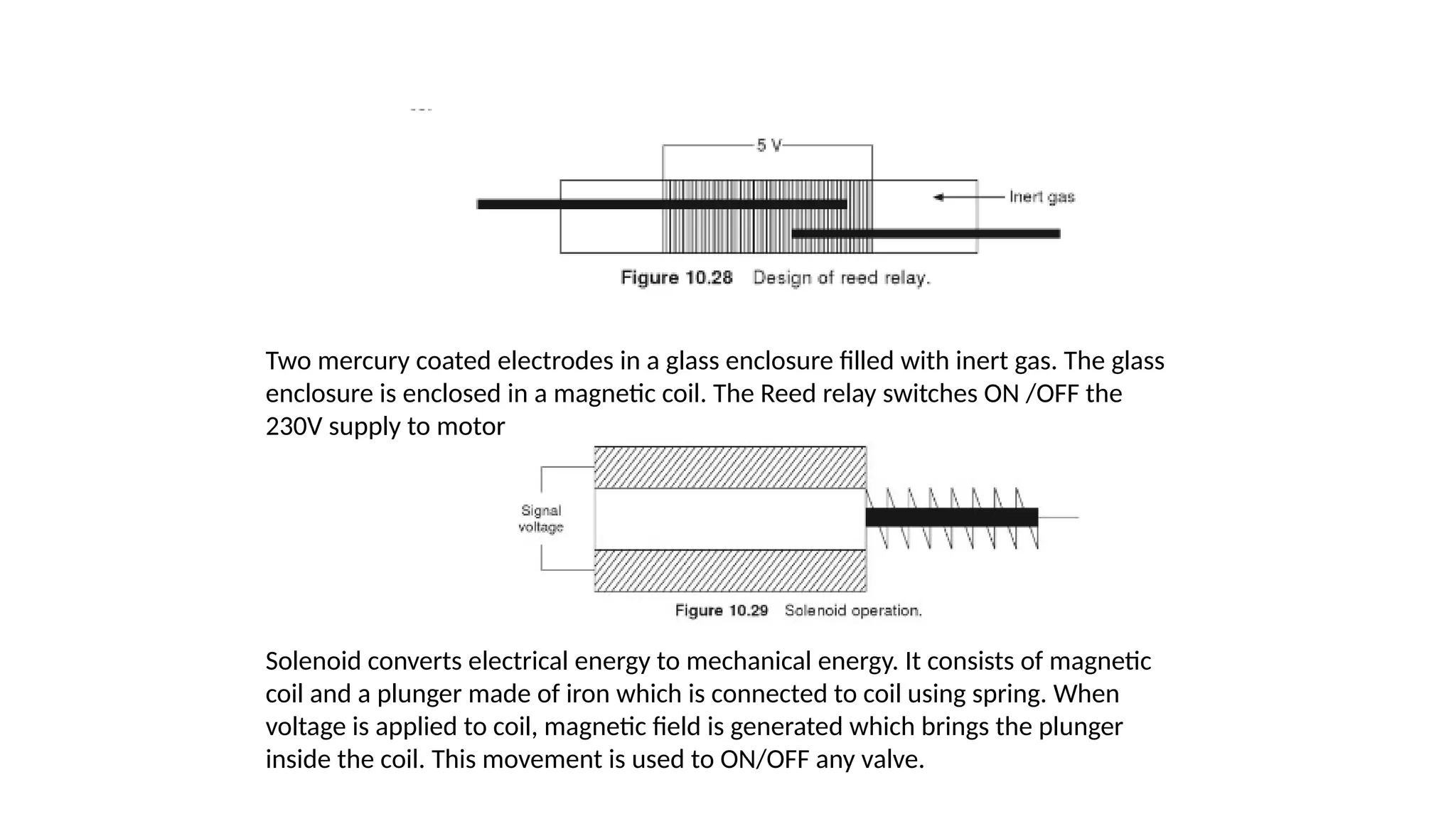
Two mercury coatedelectrodes in a glass enclosure filled with inert gas. The glass
enclosure is enclosed in a magnetic coil. The Reed relay switches ON /OFF the
230V supply to motor
Solenoid converts electrical energy to mechanical energy. It consists of magnetic
coil and a plunger made of iron which is connected to coil using spring. When
voltage is applied to coil, magnetic field is generated which brings the plunger
inside the coil. This movement is used to ON/OFF any valve.
74.
• The reedrelay on receipt of command from microprocessor switches
ON/OFF 230V supply to solenoid which in turn switches ON/OFF the
control valve for the supply of water to fields.
80.
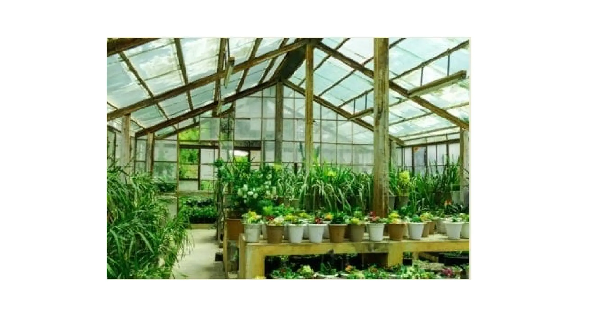
Green House
• Agreenhouse is a structure with walls and roof made of
transparent material, such as glass, in
which plants requiring regulated climatic conditions are
grown.
• These structures range in size from small sheds to
industrial-sized buildings. A miniature greenhouse is known
as a cold frame.
• The interior of a greenhouse exposed to sunlight becomes
significantly warmer than the external temperature,
protecting its contents in cold weather.
81.
• Many commercialglass greenhouses s are high
tech production facilities for vegetables, flowers or
fruits.
• The glass greenhouses are filled with equipment
including screening installations, heating, cooling,
lighting, and may be controlled by a computer to
optimize conditions for plant growth.
• Different techniques are then used to evaluate
optimality degrees and comfort ratio of greenhouses,
such as air temperature, relative
humidity and vapour-pressure deficit, in order to
reduce production risk prior to cultivation of a specific
crop.
89.
Green House Instrumentation
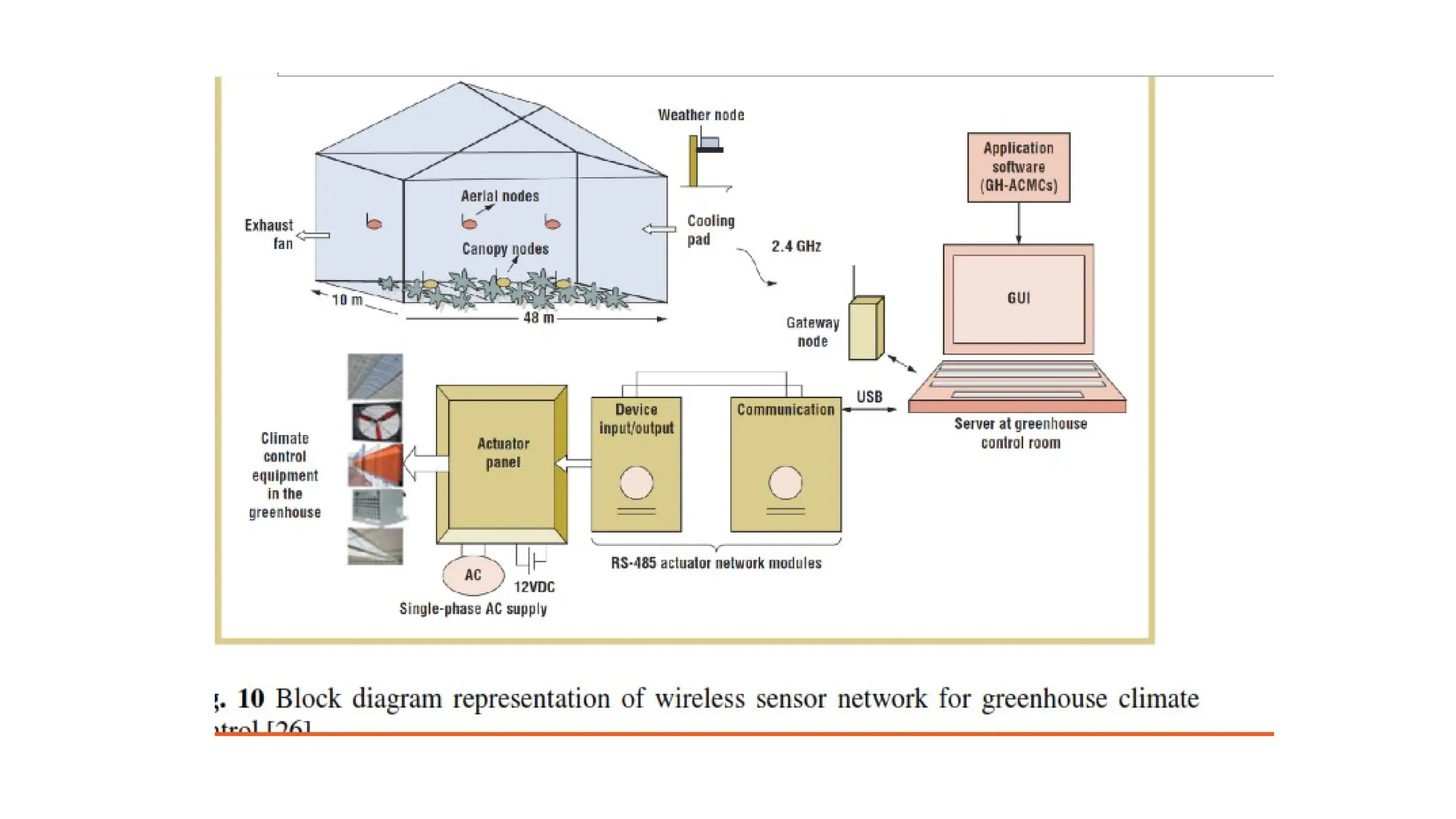
•Green House Monitoring system includes hardware,
software and database for data analysis.
• The system measures the parameters such as
temperature, humidity, vapour pressure and others that
are linked to the growth and health of crops at micro
level.
• The sensor data is sent to home gateway USB
coordinator through wireless RF communication device.
The data is logged to database server and graphical user
interface has been developed for users.
• The most interesting part of the system is the
automated control to maintain and control the essential
parameter values inside the greenhouse.
90.
• For automatedcontrol, the RS-485 actuator control
module is connected to the actuator panel that
governs the climate control equipment such as
cooling, watering, etc.
• The web-based wireless sensors and networks have
been realised for agriculture land, to detect the
temperature, humidity and pH level of soil for crop
growth.
• The system is based on the ZigBee protocol for
wireless RF communication.
• Plant tissueculture is a collection of techniques used
to maintain or grow plant cells, tissues or organs
under sterile conditions on a nutrient culture medium
of known composition. It is widely used to produce
clones of a plant in a method known as micro
propagation.
93.
Advantages of tissueculture over traditional method of
propagation
• The production of exact copies of plants that produce
particularly good flowers, fruits, or have other
desirable traits.
• To quickly produce mature plants.
• The production of multiples of plants in the absence
of seeds or necessary pollinators to produce seeds.
• The regeneration of whole plants from plant cells that
have been genetically modified.
94.
• The productionof plants in sterile containers that
allows them to be moved with greatly reduced
chances of transmitting diseases, pests, and
pathogens (virus or other microorganism that can
cause disease).
• The production of plants from seeds that otherwise
have very low chances of germinating and growing,
i.e. orchids and Nepenthes.
• To clean particular plants of viral and other infections
and to quickly multiply these plants as 'cleaned stock'
for horticulture and agriculture.
95.
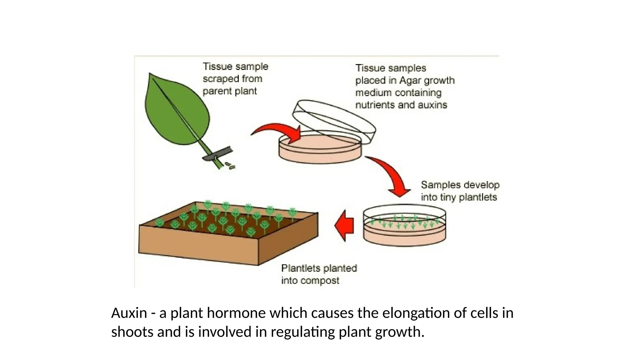
Auxin - aplant hormone which causes the elongation of cells in
shoots and is involved in regulating plant growth.
96.
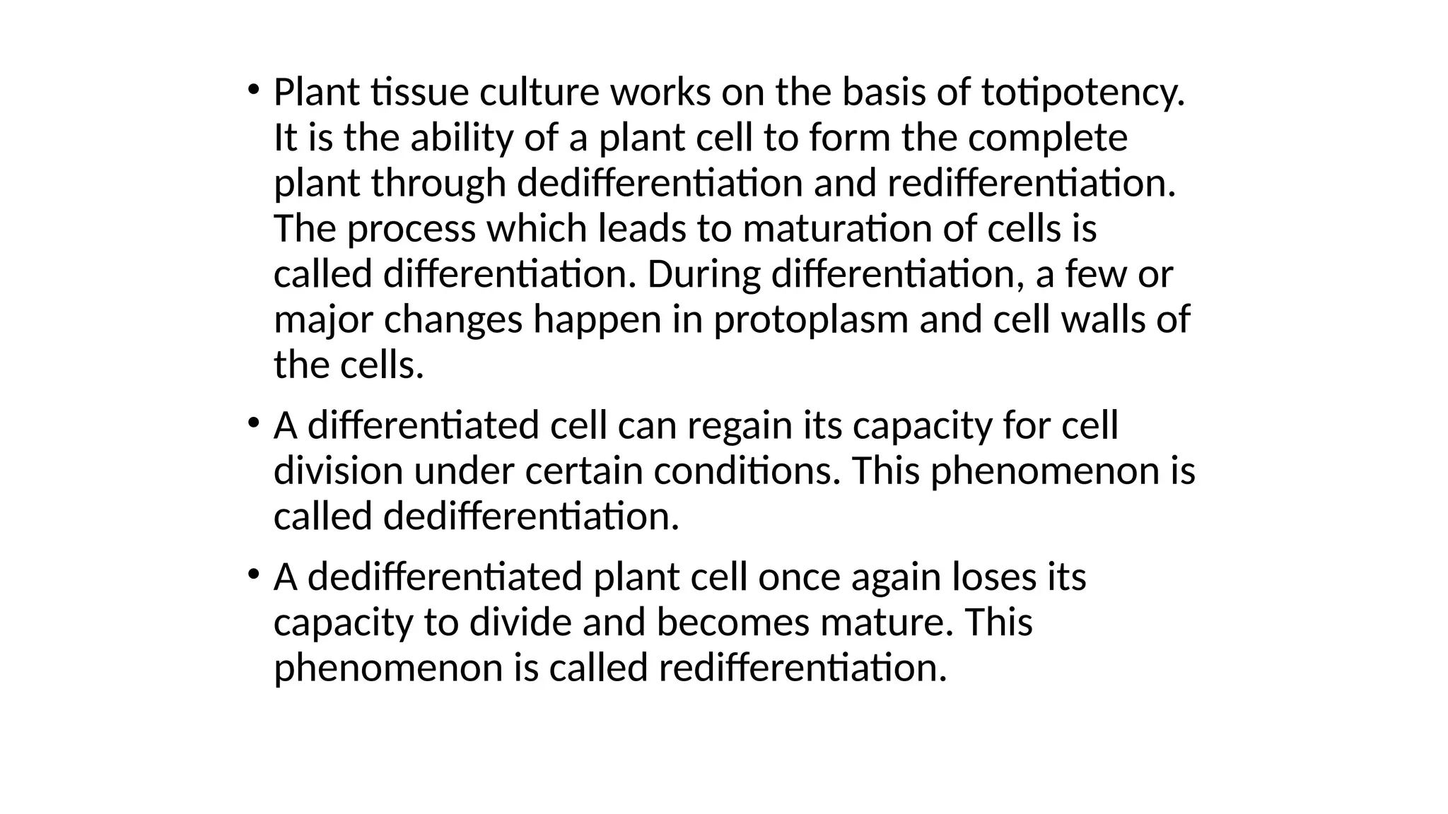
• Plant tissueculture works on the basis of totipotency.
It is the ability of a plant cell to form the complete
plant through dedifferentiation and redifferentiation.
The process which leads to maturation of cells is
called differentiation. During differentiation, a few or
major changes happen in protoplasm and cell walls of
the cells.
• A differentiated cell can regain its capacity for cell
division under certain conditions. This phenomenon is
called dedifferentiation.
• A dedifferentiated plant cell once again loses its
capacity to divide and becomes mature. This
phenomenon is called redifferentiation.
97.
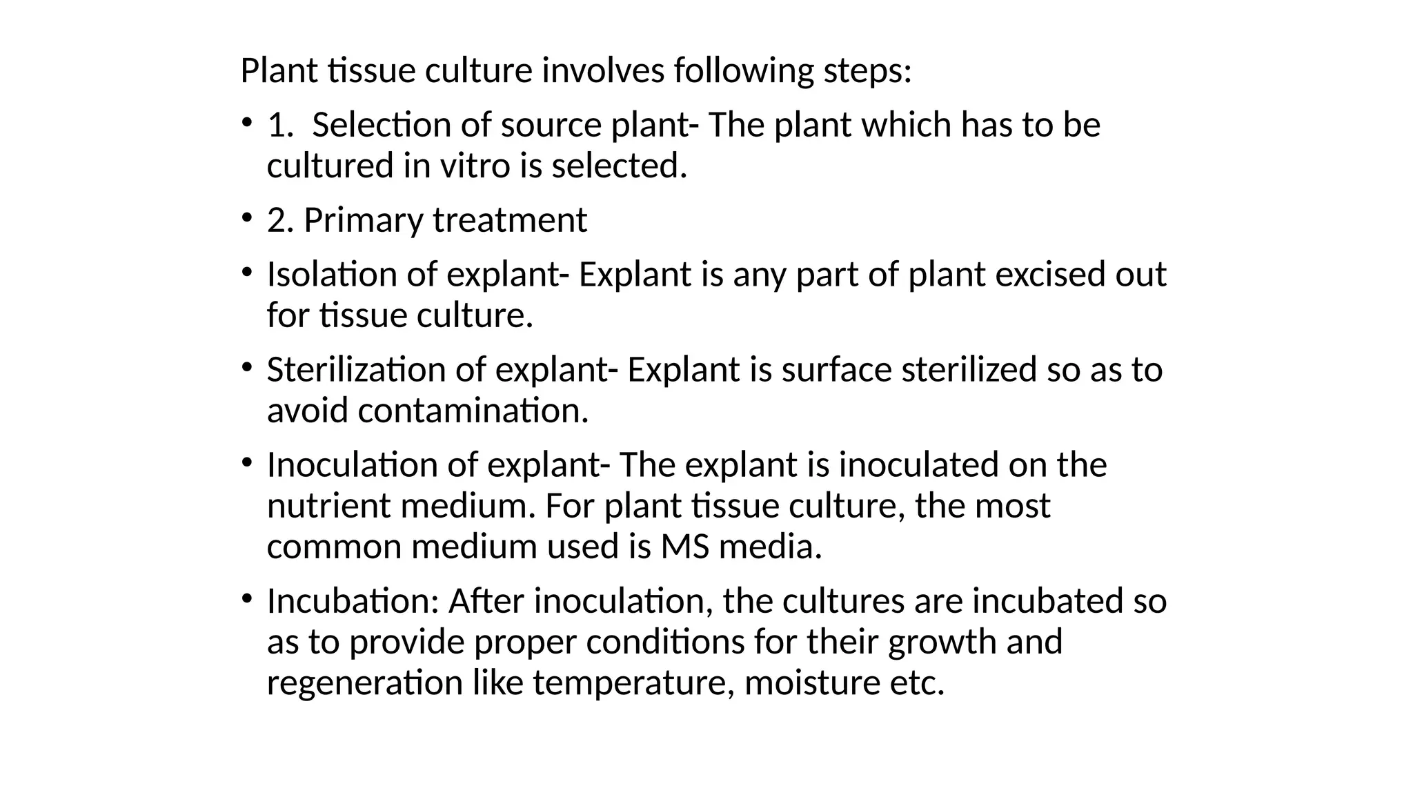
Plant tissue cultureinvolves following steps:
• 1. Selection of source plant- The plant which has to be
cultured in vitro is selected.
• 2. Primary treatment
• Isolation of explant- Explant is any part of plant excised out
for tissue culture.
• Sterilization of explant- Explant is surface sterilized so as to
avoid contamination.
• Inoculation of explant- The explant is inoculated on the
nutrient medium. For plant tissue culture, the most
common medium used is MS media.
• Incubation: After inoculation, the cultures are incubated so
as to provide proper conditions for their growth and
regeneration like temperature, moisture etc.
98.
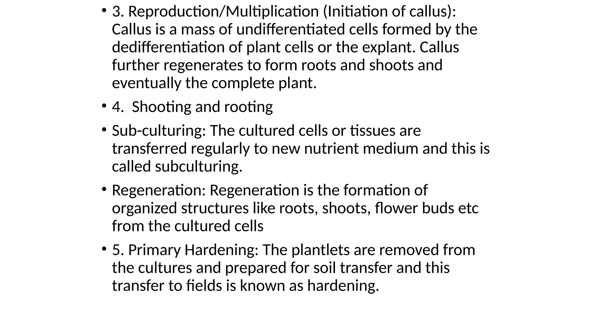
• 3. Reproduction/Multiplication(Initiation of callus):
Callus is a mass of undifferentiated cells formed by the
dedifferentiation of plant cells or the explant. Callus
further regenerates to form roots and shoots and
eventually the complete plant.
• 4. Shooting and rooting
• Sub-culturing: The cultured cells or tissues are
transferred regularly to new nutrient medium and this is
called subculturing.
• Regeneration: Regeneration is the formation of
organized structures like roots, shoots, flower buds etc
from the cultured cells
• 5. Primary Hardening: The plantlets are removed from
the cultures and prepared for soil transfer and this
transfer to fields is known as hardening.
99.
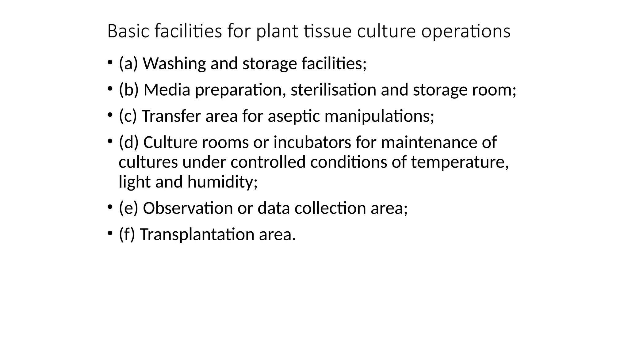
Basic facilities forplant tissue culture operations
• (a) Washing and storage facilities;
• (b) Media preparation, sterilisation and storage room;
• (c) Transfer area for aseptic manipulations;
• (d) Culture rooms or incubators for maintenance of
cultures under controlled conditions of temperature,
light and humidity;
• (e) Observation or data collection area;
• (f) Transplantation area.
100.
Washing and storagefacilities
• An area with large sink (lead lined to resist acids and
alkalis) and draining area is necessary with provision
for running water, draining-boards or racks and ready
access to a de-ionized, distilled and double-distilled
apparatus.
• Space should also be available to set up drying ovens,
washing machines, plastic or steel buckets for soaking
labware, acid or detergent baths, pipette washers,
driers and cleaning brushes.
• For storage of washed and dried labware, the
laboratory should be provided with dustproof
cupboards or storage cabinets.
101.
Media Preparation, sterilisationand storage room
• (i) Different types of glassware
• (ii) Different kinds of balances
• (iii) Required chemicals
• (iv) Hot plates and Stirrer
• (v) Water bath
• (vi) pH meter
• (vii) Autoclave and Hot air oven
• (viii) Microwave oven
• (ix) Vortex, Shaker
Transfer area
• Tissueculture techniques can only be successfully
carried out in a very clean laboratory having dry
atmosphere with protection against air-borne
microorganisms. For this purpose a sterile dust-free
room/cabinet is needed for routine transfer and
manipulation work.
104.
• The ‘laminarair flow cabinet’ is the most common
accessory used for aseptic manipulations now-a-days.
(free from contamination caused by harmful bacteria,
viruses, or other microorganisms; surgically sterile or
sterilized).
• The cabinet may be designed with horizontal air flow
or vertical air flow where the air is forced into the
cabinet through a bacterial HEPA (High Efficiency
Particulate Air) filter. The air flows over the working
bench at a constant rate which prevents the particles
(microorganisms) from settling on the bench.
105.
• Before operationin the laminar air flow cabinet, the
interior of the cabinet is sterilised with the ultraviolet
(UV) germicidal light and wiping the floor of cabinet
with 70% alcohol. Inoculation chamber, a specially
designed air tight glass chamber fitted with UV light,
may also be used as transfer area.
106.
Culture Room
• Planttissue cultures should be incubated under
conditions of well-controlled temperature,
illumination, photoperiod, humidity and air
circulation. Incubation culture rooms, commercially
available incubator cabinets, large plant growth
chambers and walk-in- environmental rooms satisfy
these requirements.
• Culture rooms are constructed with proper air-
conditioning; perforated shelves to support the
culture vessels, fitted with fluorescent tubes having a
timing device to maintain the photoperiod, black
curtains may be used to maintain total darkness.
107.
• For thesuspension cultures, gyratory shakers are
used. Air conditioners and heaters are used to
maintain the temperature around 25 ± 2°C and
humidity is maintained by uniform forced air-
ventilation.
108.
Data Collection Area
•The growth and development of tissues cultured in
vitro (within the glass) are generally monitored by
observing cultures at regular intervals in the culture
room or incubators where they have been maintained
under controlled environmental conditions.
• Arrangement should be there where the observations
can be done under aseptic conditions using
microscope. Special facilities are required for
germplasm (living genetic resources) conservation i.e.,
cryopreservation (cold) accessories should be there.
109.
Transplantation area
• Plantsregenerated from in vitro tissue culture are
transplanted to soil in pots. The potted plants are
ultimately transferred to greenhouse but prior to
transfer the tissue culture grown plants are allowed
for acclimatization under well humid condition and
controlled temperature and under controlled entry of
sunlight.
110.
Tissue culture instrumentation– pH meter
• pH as a convenient way of expressing hydrogen ion
concentration. pH of a solution is strictly defined as
the negative logarithm of hydrogen ion concentration.
• pH = – log10 (H+
) = 7
• The pH of pure water is 7 at 25 °C. Generally glass
distilled water is used for the preparation of culture
medium. However, sometimes buffered solutions may
be used for the same to keep the pH of the medium
constant.
111.
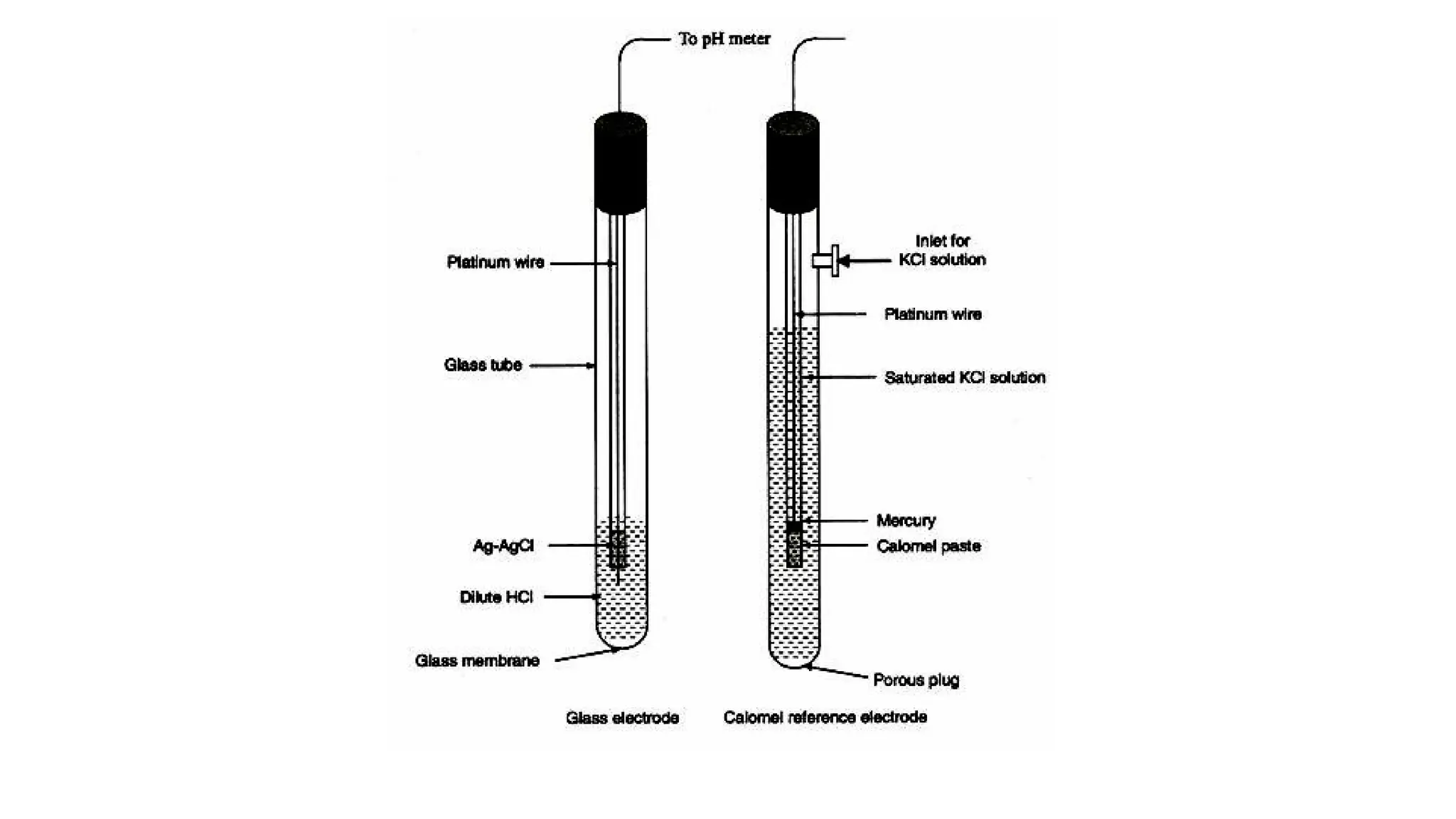
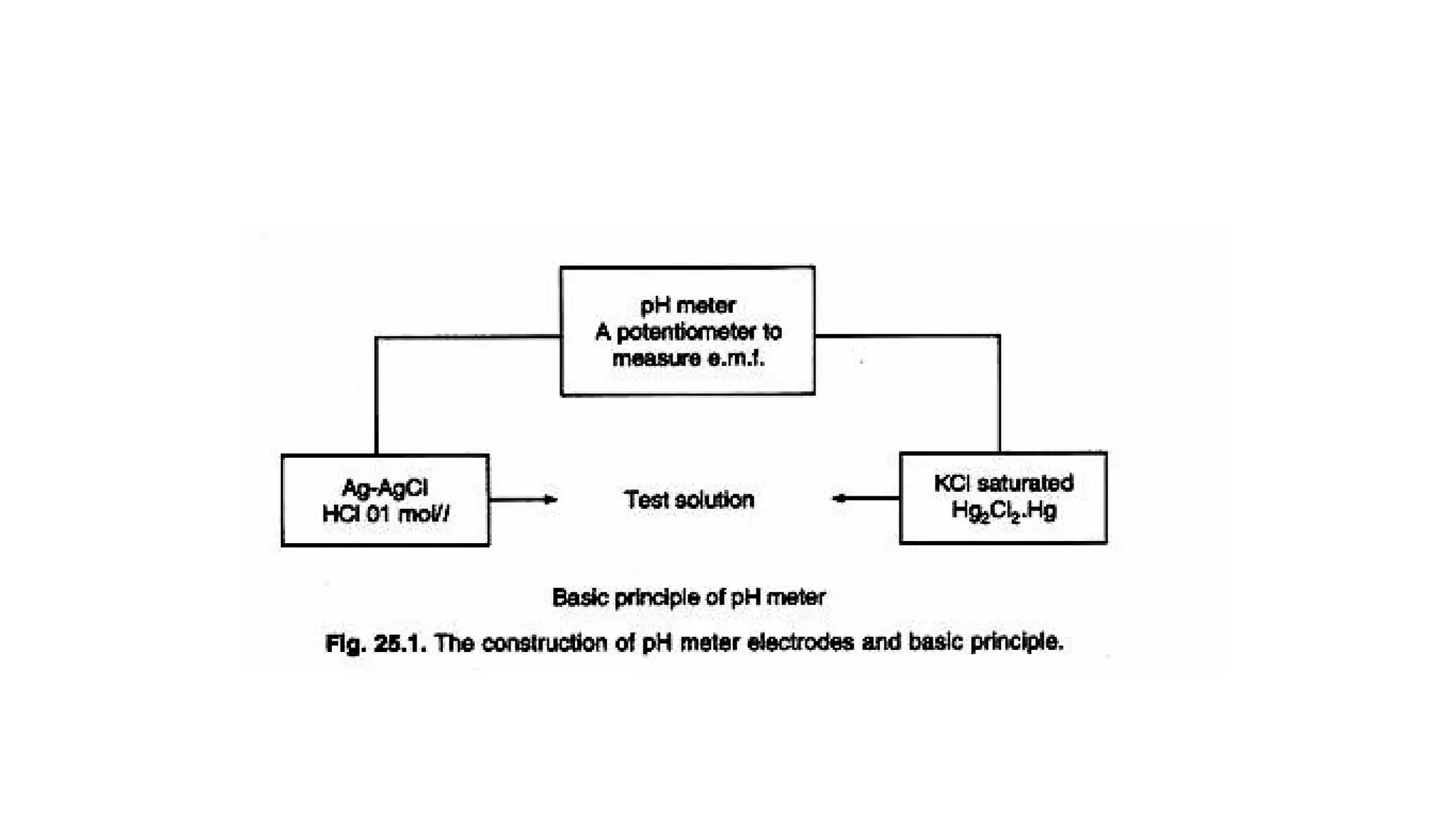
pH meter
• Astandard pH meter has two electrodes, one glass
electrode for measuring pH and the other calomel
reference electrode.
• Reference electrode is filled with saturated KCI
solution.
• Indicator = Indicator–
+ H+
114.
• The pHprobe measures pH as the activity of hydrogen
ions surrounding a thin walled glass bulb at its tip. The
probe produces a small voltage (about 0.06 volt per
pH unit) that is measured and displayed as pH units by
the meter.
• The meter circuit is fundamentally a voltmeter that
displays measurements in pH units instead of volts.
115.
• The circuitof a simple pH meter usually consists of
operational amplifiers in an inverting configuration,
with a total voltage gain of about – 17. The inverting
amplifier converts the small voltage produced by the
probe (+ 0.059 volt/pH) into pH units, which are then
offset by seven volts to give a reading on the pH scale.
116.
• (i) Atneutral pH (pH 7) the voltage at the probe’s
output is 0 volts.
• (ii) At alkaline pH, the voltage at the probe’s output
ranges from + 0 to + 0.41
• (iii) At acid pH, the voltage at the probe’s output
ranges from – 0.41 volts to – 0.
117.
Applications
• 1. Toadjust pH of different solutions, preparation of buffers and
culture media.
• 2. Determination of pH of cells (cell sap) and in analytical techniques.
• 3. To monitor pH of the medium in a bioreactor.
118.
Autoclave
• Autoclave isused to sterilize medium, glassware and
tools for the purpose of plant tissue culture.
• Sterilization of material is carried out by increasing
moist heat (121 °C) due to increased pressure inside
the vessel (15-22 psi, pounds per square inch or 1.02
to 1.5 kg/cm2
) for 15 minutes for routine sterilization.
• Moist heat (Ex.Steam) kills the microorganism and
makes the material free from microbes.
119.
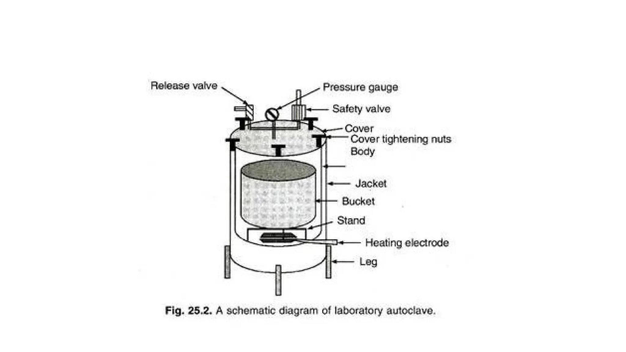
Construction
• Autoclaves ofdifferent sizes from 5 litres to several
hundred litres capacity are available in horizontal or
vertical designs.
• An autoclave have a body, an internal heating system,
a container to hold material, its cover fixed with
pressure gauge, safety valve, pressure release valve
etc.
120.
• Lid istightened with the help of screws and a gasket
seals the body and lid. A jacket, paddle lifter, timer,
and indicator etc., are also provided with large sized
autoclaves.
• Autoclaves may be constructed of aluminum, mild
steel, stainless steel or gun metal.
• Industrial autoclave can accommodate large trolley
containing huge number of glassware’s or large
bioreactors.
122.
Operation
• Place thematerials (wrapped in aluminum foil or
paper or in metal box) and glass-wares containing
medium (plugged with non-absorbent cotton and
covered with aluminum foil) in the bucket.
• Check water level for appropriate level, tighten all the
screws, and switch-on the current. Allow the steam to
pass freely from release valve for 5 minutes and then
close the valve.
123.
• After attaininga pressure of 15 psi, count 15 minutes
for sterilization and then switch-off the current.
Pressure is maintained by safety valve. Modern
autoclaves are fitted with temperature and time
control units and can automatically control the period
for sterilization and then switch-off themselves.
• Empty vessels, beakers, graduated cylinders, etc.,
should be closed with a cap or aluminum foil. Tools
should also be wrapped in foil or paper or put in a
covered sterilization tray. It is critical that the steam
penetrate the items in order for sterilization to be
successful.
124.
Plant growth chamber
•Plant growth chambers can be constructed in a
suitable sized room or can be purchased as
commercially available equipment. Thermal insulation
of walls increases the efficiency of the cooling system.
• Essentially plant growth chamber has three
environmental control systems:
• 1. Light-intensity and duration cycle control.
• 2. Temperature control and regulation.
• 3. Humidity control and regulation.
125.
• All themodern instruments are electronically
controlled precision instruments with sophisticated
sensors and timers to regulate the desired set values.
• Light
• Light is fixed in the roof of equipment or in shelves.
Light is provided by commercially available light
sources like cool white fluorescent tubes and
incandescent lamps in a ratio of 3:1 and usually a light
intensity of 2000-2500 lux (about 200-250 candles or
30 µ mol m-2
s1
) is used. The duration of light and dark
cycle is adjusted as per requirement, usually 16 hours
light cycle is given.
126.
Temperature
• In modernequipment, temperature is precisely
regulated by good quality (platinum) temperature
sensor.
• In all cases, air conditioning units provide the cooling. It
is always advisable to keep one spare compressor unit,
for emergency, to avoid delay in repairs and damage to
cultures.
• Usually temperature of 22-28 °C is used for growing plant
tissue culture.
• Temperatures should be measured in a constructed
growth chamber at different levels and places, viz., light
racks, central and corners to have a correct temperature
setting.
127.
Humidity
• Humidity insidethe growth chamber is provided by
humidifier (a mist generating system) and controlled
by humidistat.
• Usually 60% RH (relative humidity) is used to maintain
healthy growth.
• Low RH may cause early drying of medium while high
humidity may cause fungal growth in the environment
and on a various articles.
• Thus, in a growth chamber, light, temperature and
humidity are precisely controlled and cultures are
grown in a controlled environment. All the controls
are set on control panel.
128.
Laminar Air FlowBench
• Laminar air flow (LAF) bench is the main working
table for aseptic manipulations related to plant tissue
culture.
• This is equipment fitted with High Efficiency
Particulate Air (HEPA) Filters, which allow air to pass
but retain all the particles and micro-organisms.
These HEPA Filters have a very small pore size (0.3
µm) with 99.97-99.99% efficiency.
129.
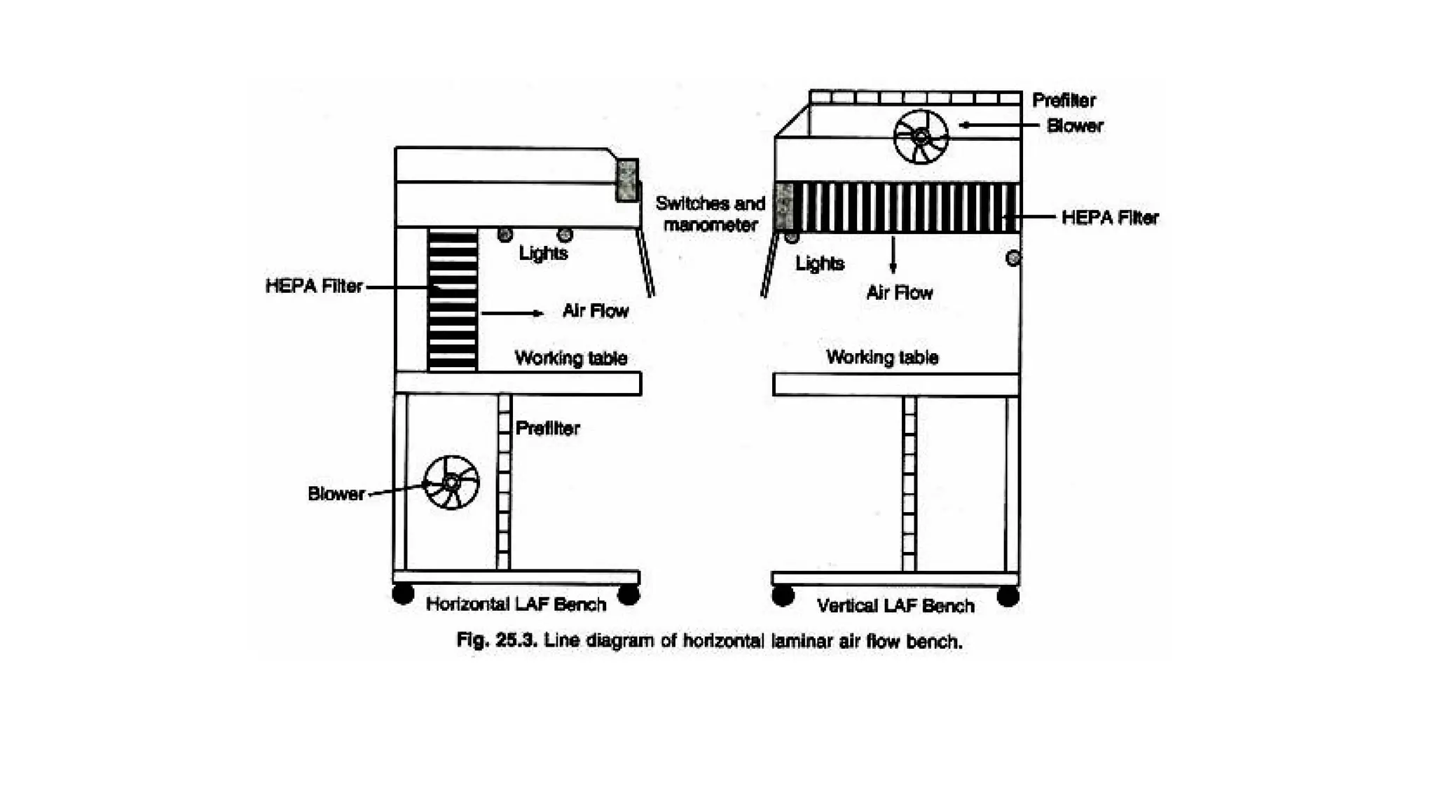
• UV isswitched-on for 30 minutes before starting the
work to make area free from microbes. LAF Bench of
steel and wooden cabinets is available with different
working table size and for vertical (downward air
flow) or horizontal (horizontal flow) model.
• HEPA filters are also used to create ‘clean area’ for
culture rooms and inoculation room etc. If LAF bench
is placed in such a clear area, efficiency and life of the
equipment are increased.
131.
Calorimeter
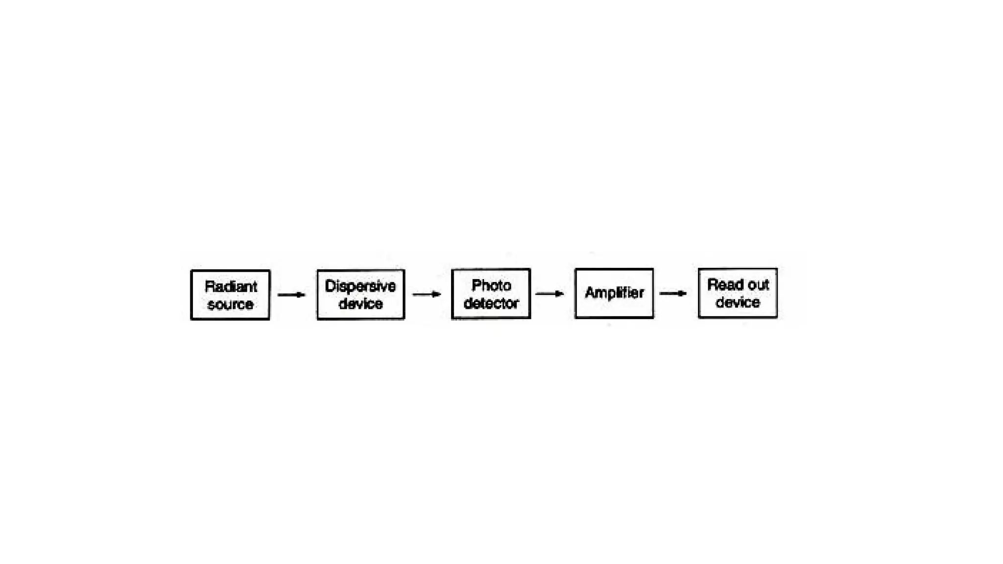
• The mostcommonly used method for determining
the concentration of biochemical compounds is
colorimetry. It uses the property of light such that
when white light passes through a coloured solution,
some wavelengths are absorbed more than others.
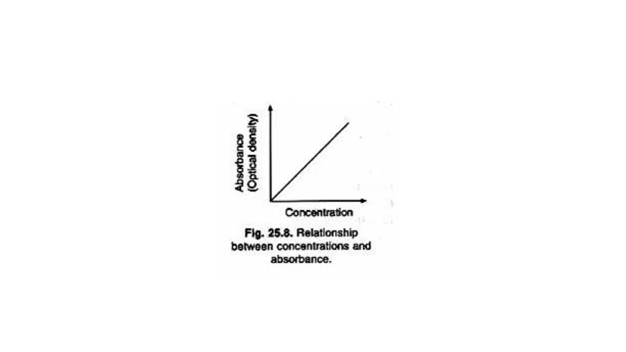
• The depth of colour is directly proportional to the
concentration of the compound being measured,
while the amount of light absorbed is proportional to
the intensity of the colour and therefore, to the
concentration.
133.
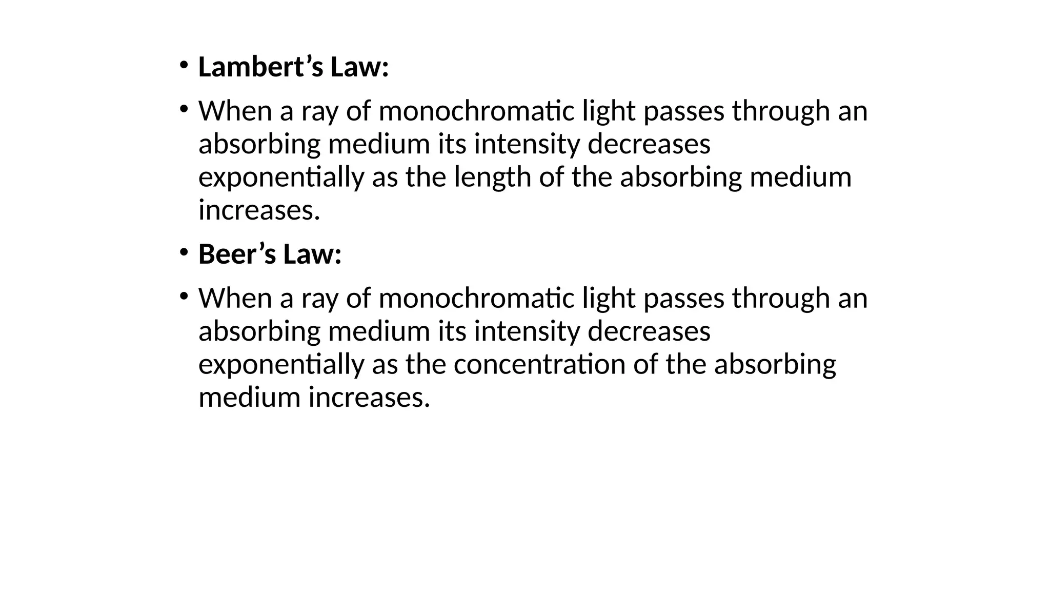
• Lambert’s Law:
•When a ray of monochromatic light passes through an
absorbing medium its intensity decreases
exponentially as the length of the absorbing medium
increases.
• Beer’s Law:
• When a ray of monochromatic light passes through an
absorbing medium its intensity decreases
exponentially as the concentration of the absorbing
medium increases.
135.
Medium and itspreparation
• The nutrient medium for most plant tissue cultures is comprised of
five groups of ingredients – inorganic nutrients, carbon source,
vitamins, growth regulators and organic supplements.
136.
Inorganic nutrients
• Usuallynutrient media contain 25 mM each of nitrate and potassium.
(milli Molar)
• For regular culture and cell cultures, the combined nitrogen level
(nitrate and ammonium nitrogen) may reach up to 60 mM.
• Ammonium is essential for most cultures but in lower concentrations
than that of nitrate nitrogen. A concentration of 1-3 mM of calcium,
magnesium and sulphate, is always adequate.
137.
Carbon Source
• Glucose,fructose, maltose or sucrose (2-4%) can be
used as source of energy or carbon but sucrose is the
preferred source for most of the cultures. The sucrose
in the medium is rapidly converted into glucose and
fructose. The glucose is absorbed first followed by
fructose.
138.
Vitamins and aminoacids
•Thiamine, pyridoxine and nicotinic acid are commonly used as
vitamins in B5 and MS media (Murashige and Skoog medium). The
former is required for most cultures while latter two promote cell
growth.
• Amino acids serve as source of reduced nitrogen.
139.
Medium preparation
• Aconvenient approach to prepare a medium is to have stock
solutions of all the nutrients in a 10x or 50x concentration.
• Medium is prepared by suitably diluting the appropriate amount of
stock solutions for desired volume of the medium.
• It may be advantageous to have separate stock solutions of calcium
salt and potassium iodide.
140.
• All theingredients are mixed, sugar added and pH is
adjusted to 5.8-6.0 and medium is poured in the
culture vessels.
• All the vessels are plugged with non-absorbent
cotton, covered with aluminum foil and autoclaved at
121 °C for 15 min.
• Prepared media can be stored for a few weeks before
inoculation.
![Barometers are used to measure the
current air pressure at a particular
location in "inches of mercury" or in
‘mill bars’ (mb). [29.92 inches of
mercury is equivalent to 1013.25 mb].
•
The commonly used barometer in
meteorological observatories is
Fortin’s barometer.
•
Barograph :Continuous recording of
pressure is made with this instrument.
9. Barometer](https://image.slidesharecdn.com/unit-3jenitha-250402091548-ed03a82f/75/sensors-utilized-in-agro-meteorology-sdes-21-2048.jpg)