More Related Content

PPT
Cellular mobile communication 
PDF
1. introduction to wireless communication 
PPTX
Global System for Mobile (GSM) 
PPTX
TELECOMMUNICATIONS SYSTEMS 
PDF

PPTX

PDF

PPTX
What's hot

PPT

PPTX

PPTX

PPTX
satellite communication- UNIT-III.pptx 
DOC
Elementos del sistema de comunicaciones satelital 
PPTX

PPTX

PPTX
![Gsm rf-optimization[1]](https://cdn.slidesharecdn.com/ss_thumbnails/gsm-rf-optimization1-130923044142-phpapp02-thumbnail.jpg?width=640&height=640&fit=bounds)
PDF

PPTX
Introduction to spred spectrum and CDMA 
PPT

PPT
Global system for mobile communication(GSM) 
PPT

PDF

PPTX
Wireless communication , by Mulatu Gebeyeaw 
PPTX

PPTX

PPT

PPTX
Vsat basics - an ExploreGate tutorial 
PPT
Similar to L2-Locomotion Systems.mobile robotics ppt

PDF
Overview of different techniques utilized in designing of a legged robot 
PPTX
Presentation on robotics project 20.pptx 
PPTX
slide introduction to Autonomous Robot.pptx 
PPTX

PDF
Six Legged Walking Mechanism 
PPTX
Legged_Mobile_Robots_Presentation.pptxhj 
PPTX
ppt on rocker bogie mechanism 
PDF
IRJET-Conceptual Design of Locomotion Mechanism of an Amphibial Robot 
PDF
20AD701 - AI in Robotics - ALL UNITs PPT 
PPTX

PPTX

PPTX

PDF
Biomimetics 04_15Unmanned Systems_web 
PDF
International Journal of Computational Engineering Research (IJCER) 
PDF
Vehicle-applicable robots controlled byMobile 
PDF
Development of a quadruped mobile robot and its movement system using geometr... 
DOC

PPT

PDF
Rocker-Bogie-Project-Report.pdf 
PDF
Wheeled Mobile Robotics From Fundamentals Towards Autonomous Systems 1st Edit... More from Jenitha Rajadurai

PPTX
counter design logic devices for sequential circuit 
PDF
Planning and Navigation in mobile robotics 
PDF
mobile robot localization techniques and methods 
PPTX
sensors utilized in agro meteorology sdes 
PPTX
microprocessor in agriculture processese 
PPT
scada_classification based power point presentation 
PPTX
Agrielectronics related ppt slide for study purpose 
PPTX
datalogger-171219094658 used for agriculture 
PPTX
MCQ for agriculture electronics for engineers 
PPTX
Moses vaadhaigal suday school power point presentation 
PPT
programming logic controller and programming 
PPT
PP.SinglePhase.01.ppt variable frequency drive 
PPTX
switches-210802065050.pptx switches and types 
PPTX
Thermal sensors_thermal mapping_unit iv.pptx 
PPTX
display technology used in agriculture automation 
PPTX
final ppt soil moisture transducer use in agriculture 
PPTX
programmable logic controller functions of plc 
PPT
the basis of photosynthesis and their steps 
PPTX
Chapter-5-Photosynthesis stages and growth 
PPTX
programmable logic controller and automation Recently uploaded

PDF
Shear Strength of Soil (Direct shear test).pdf 
PDF
Industrial Tools Manufacturers In India : Torso Tools 
PDF
Plasticity and Structure of Soil/Atterberg Limits.pdf 
PPTX
This Bearing Didn’t Fail Suddenly — How Vibration Data Predicts Failure Month... 
PPTX
Fuel Injection Pump Test Bench – Precision Testing & Calibration for Diesel E... 
PDF
Chemical Hazards at Workplace – Types, Properties & Exposure Routes, CORE-EHS 
PPTX
Why TPM Succeeds in Some Plants and Struggles in Others | MaintWiz 
PDF
Decision-Support-Systems-and-Decision-Making-Processes.pdf 
PDF
Weak Incentives (WINK): The Agent Definition Layer 
PDF
Applications of AI in Civil Engineering - Dr. Rohan Dasgupta 
PPTX
uADPF Topology_SFP requirements_locked slides.pptx 
PPT
Oracle Advanced subquery and types of subquery 
PDF
PROBLEM SLOVING AND PYTHON PROGRAMMING UNIT 3.pdf 
PDF
Ericsson 6230 Training Module Document.pdf 
PDF
Rajesh Prasad- Brief Profile with educational, professional highlights 
PDF
Computer Network Lab Manual ssit -kavya r.pdf or Computer Network Lab Manual ... 
PDF
engineering management chapter 5 ppt presentation 
PPTX
Designing Work for Humans, Not Machines: Human-Centered Maintenance Excellence 
PDF
Highway Curves in Transportation Engineering.pdf 
PPTX
A professional presentation on Cosmos Bank Heist L2-Locomotion Systems.mobile robotics ppt
- 1.
MUSES_SECRET: ORF-RE Project- © PAMI Research Group – University of Waterloo 1/22
1
L2, SPC418: Autonomous Vehicles Design and Control- Zewail City of Science and Technology - Fall 2016 © Dr. Alaa Khamis
Lecture 2 – Wednesday October 5, 2016
Locomotion Systems and Kinematics
Most of the slides are based on Chapter 2 of R. Siegwart and I. Nourbakhsh. Introduction to Autonomous Mobile Robots. MIT Press, 2004.
- 2.
MUSES_SECRET: ORF-RE Project- © PAMI Research Group – University of Waterloo 2/22
2
L2, SPC418: Autonomous Vehicles Design and Control- Zewail City of Science and Technology - Fall 2016 © Dr. Alaa Khamis
MUSES_SECRET: ORF-RE Project - © PAMI Research Group – University of Waterloo
Objectives
When you have finished this lecture you should be able to:
• Understand different locomotion systems of ground vehicles.
• Understand legged locomotion (walking robots) characteristics
• Recognize different mobility configurations of wheeled mobile
robots (WMR) or driving robots.
• Understand the concepts of Holonomicity, Mobility, Steerability
and Maneuverability.
• Understand how to drive kinematics equations for wheeled
mobile robots.
- 3.
MUSES_SECRET: ORF-RE Project- © PAMI Research Group – University of Waterloo 3/22
3
L2, SPC418: Autonomous Vehicles Design and Control- Zewail City of Science and Technology - Fall 2016 © Dr. Alaa Khamis
MUSES_SECRET: ORF-RE Project - © PAMI Research Group – University of Waterloo
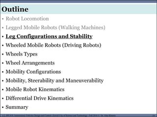
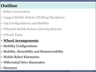
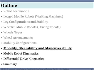
• Robot Locomotion
• Legged Mobile Robots (Walking Machines)
• Leg Configurations and Stability
• Wheeled Mobile Robots (Driving Robots)
• Wheels Types
• Wheel Arrangements
• Mobility Configurations
• Mobility, Steerability and Maneuverability
• Mobile Robot Kinematics
• Differential Drive Kinematics
• Summary
Outline
- 4.
MUSES_SECRET: ORF-RE Project- © PAMI Research Group – University of Waterloo 4/22
4
L2, SPC418: Autonomous Vehicles Design and Control- Zewail City of Science and Technology - Fall 2016 © Dr. Alaa Khamis
MUSES_SECRET: ORF-RE Project - © PAMI Research Group – University of Waterloo
• Robot Locomotion
• Legged Mobile Robots (Walking Machines)
• Leg Configurations and Stability
• Wheeled Mobile Robots (Driving Robots)
• Wheels Types
• Wheel Arrangements
• Mobility Configurations
• Mobility, Steerability and Maneuverability
• Mobile Robot Kinematics
• Differential Drive Kinematics
• Summary
Outline
- 5.
MUSES_SECRET: ORF-RE Project- © PAMI Research Group – University of Waterloo 5/22
5
L2, SPC418: Autonomous Vehicles Design and Control- Zewail City of Science and Technology - Fall 2016 © Dr. Alaa Khamis
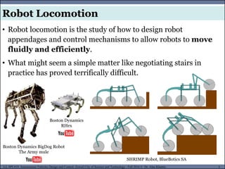
Robot Locomotion
• Robot locomotion is the study of how to design robot
appendages and control mechanisms to allow robots to move
fluidly and efficiently.
• What might seem a simple matter like negotiating stairs in
practice has proved terrifically difficult.
SHRIMP Robot, BlueBotics SA
Boston Dynamics BigDog Robot
The Army mule
Boston Dynamics
RHex
- 6.
MUSES_SECRET: ORF-RE Project- © PAMI Research Group – University of Waterloo 6/22
6
L2, SPC418: Autonomous Vehicles Design and Control- Zewail City of Science and Technology - Fall 2016 © Dr. Alaa Khamis
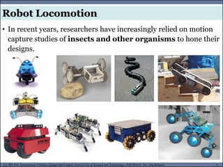
Robot Locomotion
• In recent years, researchers have increasingly relied on motion
capture studies of insects and other organisms to hone their
designs.
- 7.
MUSES_SECRET: ORF-RE Project- © PAMI Research Group – University of Waterloo 7/22
7
L2, SPC418: Autonomous Vehicles Design and Control- Zewail City of Science and Technology - Fall 2016 © Dr. Alaa Khamis
Robot Locomotion
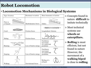
• Locomotion Mechanisms in Biological Systems
◊ Concepts found in
nature difficult to
imitate technically
◊ Most technical
systems use
wheels or
caterpillars.
◊ Rolling is most
efficient, but not
found in nature
However, the
movement of a
walking biped
is close to rolling.
- 8.
MUSES_SECRET: ORF-RE Project- © PAMI Research Group – University of Waterloo 8/22
8
L2, SPC418: Autonomous Vehicles Design and Control- Zewail City of Science and Technology - Fall 2016 © Dr. Alaa Khamis
Robot Locomotion
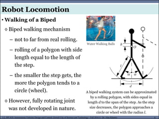
• Walking of a Biped
A biped walking system can be approximated
by a rolling polygon, with sides equal in
length d to the span of the step. As the step
size decreases, the polygon approaches a
circle or wheel with the radius l.
◊ Biped walking mechanism
– not to far from real rolling.
– rolling of a polygon with side
length equal to the length of
the step.
– the smaller the step gets, the
more the polygon tends to a
circle (wheel).
◊ However, fully rotating joint
was not developed in nature.
Water Walking Balls
- 9.
MUSES_SECRET: ORF-RE Project- © PAMI Research Group – University of Waterloo 9/22
9
L2, SPC418: Autonomous Vehicles Design and Control- Zewail City of Science and Technology - Fall 2016 © Dr. Alaa Khamis
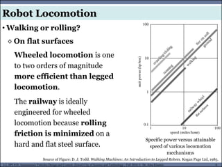
Robot Locomotion
Specific power versus attainable
speed of various locomotion
mechanisms
Wheeled locomotion is one
to two orders of magnitude
more efficient than legged
locomotion.
The railway is ideally
engineered for wheeled
locomotion because rolling
friction is minimized on a
hard and flat steel surface.
◊ On flat surfaces
• Walking or rolling?
Source of Figure: D. J. Todd. Walking Machines: An Introduction to Legged Robots. Kogan Page Ltd, 1985.
- 10.
MUSES_SECRET: ORF-RE Project- © PAMI Research Group – University of Waterloo 10/22
10
L2, SPC418: Autonomous Vehicles Design and Control- Zewail City of Science and Technology - Fall 2016 © Dr. Alaa Khamis
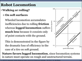
Robot Locomotion
• Walking or rolling?
Wheeled locomotion accumulates
inefficiencies due to rolling friction
whereas legged locomotion suffers
much less because it consists only
of point contacts with the ground.
This is demonstrated in the figure by
the dramatic loss of efficiency in the
case of a tire on soft ground.
◊ On soft surfaces
Nature favors legged locomotion, since locomotion systems
in nature must operate on rough and unstructured terrain.
- 11.
MUSES_SECRET: ORF-RE Project- © PAMI Research Group – University of Waterloo 11/22
11
L2, SPC418: Autonomous Vehicles Design and Control- Zewail City of Science and Technology - Fall 2016 © Dr. Alaa Khamis
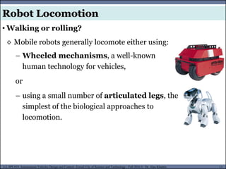
Robot Locomotion
◊ Mobile robots generally locomote either using:
• Walking or rolling?
– Wheeled mechanisms, a well-known
human technology for vehicles,
or
– using a small number of articulated legs, the
simplest of the biological approaches to
locomotion.
- 12.
MUSES_SECRET: ORF-RE Project- © PAMI Research Group – University of Waterloo 12/22
12
L2, SPC418: Autonomous Vehicles Design and Control- Zewail City of Science and Technology - Fall 2016 © Dr. Alaa Khamis
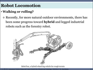
Robot Locomotion
◊ Recently, for more natural outdoor environments, there has
been some progress toward hybrid and legged industrial
robots such as the forestry robot.
• Walking or rolling?
RoboTrac, a hybrid wheel-leg vehicle for rough terrain
- 13.
MUSES_SECRET: ORF-RE Project- © PAMI Research Group – University of Waterloo 13/22
13
L2, SPC418: Autonomous Vehicles Design and Control- Zewail City of Science and Technology - Fall 2016 © Dr. Alaa Khamis
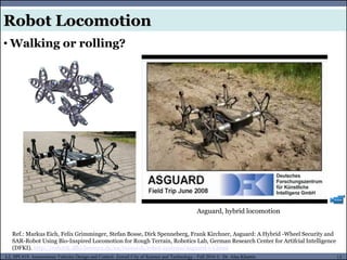
Robot Locomotion
• Walking or rolling?
Asguard, hybrid locomotion
Ref.: Markus Eich, Felix Grimminger, Stefan Bosse, Dirk Spenneberg, Frank Kirchner, Asguard: A Hybrid -Wheel Security and
SAR-Robot Using Bio-Inspired Locomotion for Rough Terrain, Robotics Lab, German Research Center for Artifcial Intelligence
(DFKI). http://robotik.dfki-bremen.de/en/research/robot-systems/asguard-i-1.html
- 14.
MUSES_SECRET: ORF-RE Project- © PAMI Research Group – University of Waterloo 14/22
14
L2, SPC418: Autonomous Vehicles Design and Control- Zewail City of Science and Technology - Fall 2016 © Dr. Alaa Khamis
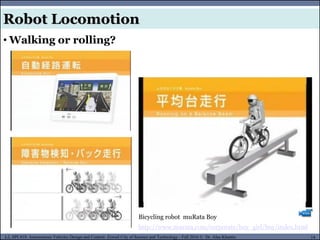
Robot Locomotion
• Walking or rolling?
Bicycling robot muRata Boy
http://www.murata.com/corporate/boy_girl/boy/index.html
- 15.
MUSES_SECRET: ORF-RE Project- © PAMI Research Group – University of Waterloo 15/22
15
L2, SPC418: Autonomous Vehicles Design and Control- Zewail City of Science and Technology - Fall 2016 © Dr. Alaa Khamis
MUSES_SECRET: ORF-RE Project - © PAMI Research Group – University of Waterloo
• Robot Locomotion
• Legged Mobile Robots (Walking Machines)
• Leg Configurations and Stability
• Wheeled Mobile Robots (Driving Robots)
• Wheels Types
• Wheel Arrangements
• Mobility Configurations
• Mobility, Steerability and Maneuverability
• Mobile Robot Kinematics
• Differential Drive Kinematics
• Summary
Outline
- 16.
MUSES_SECRET: ORF-RE Project- © PAMI Research Group – University of Waterloo 16/22
16
L2, SPC418: Autonomous Vehicles Design and Control- Zewail City of Science and Technology - Fall 2016 © Dr. Alaa Khamis
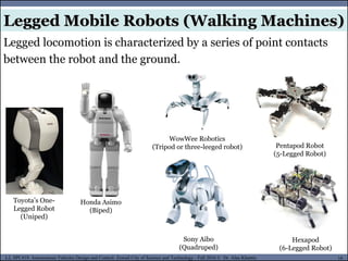
Legged Mobile Robots (Walking Machines)
Legged locomotion is characterized by a series of point contacts
between the robot and the ground.
Toyota’s One-
Legged Robot
(Uniped)
Hexapod
(6-Legged Robot)
Sony Aibo
(Quadruped)
Honda Asimo
(Biped)
WowWee Robotics
(Tripod or three-leeged robot) Pentapod Robot
(5-Legged Robot)
- 17.
MUSES_SECRET: ORF-RE Project- © PAMI Research Group – University of Waterloo 17/22
17
L2, SPC418: Autonomous Vehicles Design and Control- Zewail City of Science and Technology - Fall 2016 © Dr. Alaa Khamis
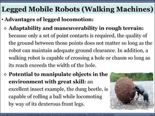
Legged Mobile Robots (Walking Machines)
• Advantages of legged locomotion:
◊ Adaptability and maneuverability in rough terrain:
because only a set of point contacts is required, the quality of
the ground between those points does not matter so long as the
robot can maintain adequate ground clearance. In addition, a
walking robot is capable of crossing a hole or chasm so long as
its reach exceeds the width of the hole.
◊ Potential to manipulate objects in the
environment with great skill: an
excellent insect example, the dung beetle, is
capable of rolling a ball while locomoting
by way of its dexterous front legs.
- 18.
MUSES_SECRET: ORF-RE Project- © PAMI Research Group – University of Waterloo 18/22
18
L2, SPC418: Autonomous Vehicles Design and Control- Zewail City of Science and Technology - Fall 2016 © Dr. Alaa Khamis
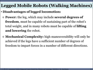
Legged Mobile Robots (Walking Machines)
• Disadvantages of legged locomotion:
◊ Power: the leg, which may include several degrees of
freedom, must be capable of sustaining part of the robot’s
total weight, and in many robots must be capable of lifting
and lowering the robot.
◊ Mechanical Complexity: high maneuverability will only be
achieved if the legs have a sufficient number of degrees of
freedom to impart forces in a number of different directions.
- 19.
MUSES_SECRET: ORF-RE Project- © PAMI Research Group – University of Waterloo 19/22
19
L2, SPC418: Autonomous Vehicles Design and Control- Zewail City of Science and Technology - Fall 2016 © Dr. Alaa Khamis
MUSES_SECRET: ORF-RE Project - © PAMI Research Group – University of Waterloo
• Robot Locomotion
• Legged Mobile Robots (Walking Machines)
• Leg Configurations and Stability
• Wheeled Mobile Robots (Driving Robots)
• Wheels Types
• Wheel Arrangements
• Mobility Configurations
• Mobility, Steerability and Maneuverability
• Mobile Robot Kinematics
• Differential Drive Kinematics
• Summary
Outline
- 20.
MUSES_SECRET: ORF-RE Project- © PAMI Research Group – University of Waterloo 20/22
20
L2, SPC418: Autonomous Vehicles Design and Control- Zewail City of Science and Technology - Fall 2016 © Dr. Alaa Khamis
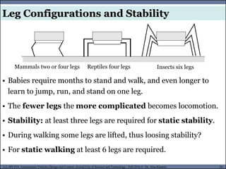
Leg Configurations and Stability
Mammals two or four legs Reptiles four legs Insects six legs
• Babies require months to stand and walk, and even longer to
learn to jump, run, and stand on one leg.
• The fewer legs the more complicated becomes locomotion.
• Stability: at least three legs are required for static stability.
• During walking some legs are lifted, thus loosing stability?
• For static walking at least 6 legs are required.
- 21.
MUSES_SECRET: ORF-RE Project- © PAMI Research Group – University of Waterloo 21/22
21
L2, SPC418: Autonomous Vehicles Design and Control- Zewail City of Science and Technology - Fall 2016 © Dr. Alaa Khamis
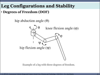
Leg Configurations and Stability
• Degrees of Freedom (DOF)
◊ A minimum of two DOF is required to move a leg forward
–Lifting the leg
– Swinging it forward.
◊ Three DOF for each leg in most cases for more complex
maneuvers.
- 22.
MUSES_SECRET: ORF-RE Project- © PAMI Research Group – University of Waterloo 22/22
22
L2, SPC418: Autonomous Vehicles Design and Control- Zewail City of Science and Technology - Fall 2016 © Dr. Alaa Khamis
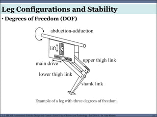
Leg Configurations and Stability
• Degrees of Freedom (DOF)
Example of a leg with three degrees of freedom.
- 23.
MUSES_SECRET: ORF-RE Project- © PAMI Research Group – University of Waterloo 23/22
23
L2, SPC418: Autonomous Vehicles Design and Control- Zewail City of Science and Technology - Fall 2016 © Dr. Alaa Khamis
Leg Configurations and Stability
• Degrees of Freedom (DOF)
Example of a leg with three degrees of freedom.
- 24.
MUSES_SECRET: ORF-RE Project- © PAMI Research Group – University of Waterloo 24/22
24
L2, SPC418: Autonomous Vehicles Design and Control- Zewail City of Science and Technology - Fall 2016 © Dr. Alaa Khamis
Leg Configurations and Stability
• Degrees of Freedom (DOF)
◊ In general, adding degrees of freedom to a robot leg
increases the maneuverability of the robot, both
augmenting the range of terrains on which it can travel and the
ability of the robot to travel with a variety of gaits.
◊ The primary disadvantages of additional joints and
actuators are, of course, energy, control, and mass.
◊ Additional actuators require energy and control, and they also
add to leg mass, further increasing power and load
requirements on existing actuators.
- 25.
MUSES_SECRET: ORF-RE Project- © PAMI Research Group – University of Waterloo 25/22
25
L2, SPC418: Autonomous Vehicles Design and Control- Zewail City of Science and Technology - Fall 2016 © Dr. Alaa Khamis
Leg Configurations and Stability
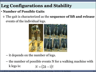
• Number of Possible Gaits
◊ The gait is characterized as the sequence of lift and release
events of the individual legs.
– it depends on the number of legs.
– the number of possible events N for a walking machine with
k legs is: !
1
2
k
N
- 26.
MUSES_SECRET: ORF-RE Project- © PAMI Research Group – University of Waterloo 26/22
26
L2, SPC418: Autonomous Vehicles Design and Control- Zewail City of Science and Technology - Fall 2016 © Dr. Alaa Khamis
Leg Configurations and Stability
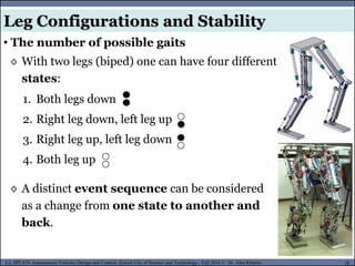
• The number of possible gaits
◊ With two legs (biped) one can have four different
states:
◊ A distinct event sequence can be considered
as a change from one state to another and
back.
1. Both legs down
2. Right leg down, left leg up
3. Right leg up, left leg down
4. Both leg up
- 27.
MUSES_SECRET: ORF-RE Project- © PAMI Research Group – University of Waterloo 27/22
27
L2, SPC418: Autonomous Vehicles Design and Control- Zewail City of Science and Technology - Fall 2016 © Dr. Alaa Khamis
Leg Configurations and Stability
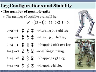
• The number of possible gaits
◊ The number of possible events N is:
12 1 turning on right leg
6
1
2
3
!
3
!
1
2
k
N
13 1 turning on left leg
14 1 hopping with two legs
23 2 walking running
24 2 hopping right leg
34 3 hopping left leg
- 28.
MUSES_SECRET: ORF-RE Project- © PAMI Research Group – University of Waterloo 28/22
28
L2, SPC418: Autonomous Vehicles Design and Control- Zewail City of Science and Technology - Fall 2016 © Dr. Alaa Khamis
Leg Configurations and Stability
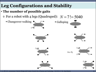
• The number of possible gaits
◊ For a robot with 4 legs (Quadruped): 5040
!
7
N
Changeover walking Galloping
- 29.
MUSES_SECRET: ORF-RE Project- © PAMI Research Group – University of Waterloo 29/22
29
L2, SPC418: Autonomous Vehicles Design and Control- Zewail City of Science and Technology - Fall 2016 © Dr. Alaa Khamis
Leg Configurations and Stability
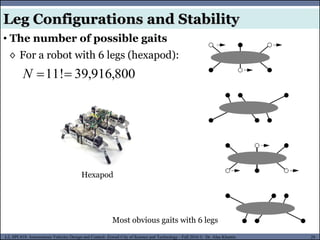
• The number of possible gaits
◊ For a robot with 6 legs (hexapod):
800
,
916
,
39
!
11
N
Most obvious gaits with 6 legs
Hexapod
- 30.
MUSES_SECRET: ORF-RE Project- © PAMI Research Group – University of Waterloo 30/22
30
L2, SPC418: Autonomous Vehicles Design and Control- Zewail City of Science and Technology - Fall 2016 © Dr. Alaa Khamis
MUSES_SECRET: ORF-RE Project - © PAMI Research Group – University of Waterloo
• Robot Locomotion
• Legged Mobile Robots (Walking Machines)
• Leg Configurations and Stability
• Wheeled Mobile Robots (Driving Robots)
• Wheels Types
• Wheel Arrangements
• Mobility Configurations
• Mobility, Steerability and Maneuverability
• Mobile Robot Kinematics
• Differential Drive Kinematics
• Summary
Outline
- 31.
MUSES_SECRET: ORF-RE Project- © PAMI Research Group – University of Waterloo 31/22
31
L2, SPC418: Autonomous Vehicles Design and Control- Zewail City of Science and Technology - Fall 2016 © Dr. Alaa Khamis
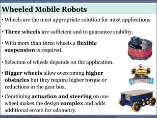
Wheeled Mobile Robots
• Wheels are the most appropriate solution for most applications
• Three wheels are sufficient and to guarantee stability.
• With more than three wheels a flexible
suspension is required.
• Selection of wheels depends on the application.
• Bigger wheels allow overcoming higher
obstacles but they require higher torque or
reductions in the gear box.
• Combining actuation and steering on one
wheel makes the design complex and adds
additional errors for odometry.
- 32.
MUSES_SECRET: ORF-RE Project- © PAMI Research Group – University of Waterloo 32/22
32
L2, SPC418: Autonomous Vehicles Design and Control- Zewail City of Science and Technology - Fall 2016 © Dr. Alaa Khamis
MUSES_SECRET: ORF-RE Project - © PAMI Research Group – University of Waterloo
• Robot Locomotion
• Legged Mobile Robots (Walking Machines)
• Leg Configurations and Stability
• Wheeled Mobile Robots (Driving Robots)
• Wheels Types
• Wheel Arrangements
• Mobility Configurations
• Mobility, Steerability and Maneuverability
• Mobile Robot Kinematics
• Differential Drive Kinematics
• Summary
Outline
- 33.
MUSES_SECRET: ORF-RE Project- © PAMI Research Group – University of Waterloo 33/22
33
L2, SPC418: Autonomous Vehicles Design and Control- Zewail City of Science and Technology - Fall 2016 © Dr. Alaa Khamis
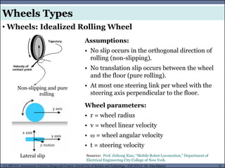
• Wheels: Idealized Rolling Wheel
Non-slipping and pure
rolling
Lateral slip
Assumptions:
• No slip occurs in the orthogonal direction of
rolling (non-slipping).
• No translation slip occurs between the wheel
and the floor (pure rolling).
• At most one steering link per wheel with the
steering axis perpendicular to the floor.
Wheel parameters:
• r = wheel radius
• v = wheel linear velocity
• = wheel angular velocity
• t = steering velocity
Source: Prof. Jizhong Xiao, “Mobile Robot Locomotion,” Department of
Electrical Engineering City College of New York.
Wheels Types
- 34.
MUSES_SECRET: ORF-RE Project- © PAMI Research Group – University of Waterloo 34/22
34
L2, SPC418: Autonomous Vehicles Design and Control- Zewail City of Science and Technology - Fall 2016 © Dr. Alaa Khamis
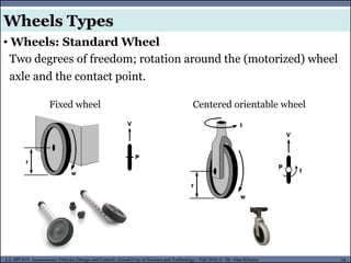
• Wheels: Standard Wheel
Two degrees of freedom; rotation around the (motorized) wheel
axle and the contact point.
Fixed wheel Centered orientable wheel
Wheels Types
- 35.
MUSES_SECRET: ORF-RE Project- © PAMI Research Group – University of Waterloo 35/22
35
L2, SPC418: Autonomous Vehicles Design and Control- Zewail City of Science and Technology - Fall 2016 © Dr. Alaa Khamis
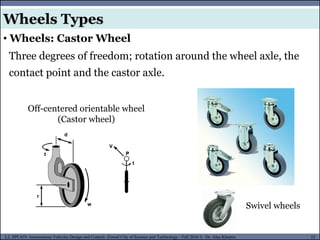
• Wheels: Castor Wheel
Three degrees of freedom; rotation around the wheel axle, the
contact point and the castor axle.
Off-centered orientable wheel
(Castor wheel)
Swivel wheels
Wheels Types
- 36.
MUSES_SECRET: ORF-RE Project- © PAMI Research Group – University of Waterloo 36/22
36
L2, SPC418: Autonomous Vehicles Design and Control- Zewail City of Science and Technology - Fall 2016 © Dr. Alaa Khamis
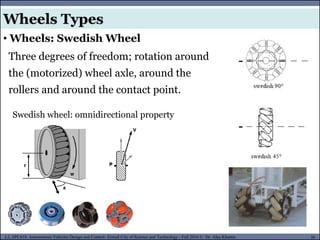
• Wheels: Swedish Wheel
Three degrees of freedom; rotation around
the (motorized) wheel axle, around the
rollers and around the contact point.
Swedish wheel: omnidirectional property
Wheels Types
- 37.
MUSES_SECRET: ORF-RE Project- © PAMI Research Group – University of Waterloo 37/22
37
L2, SPC418: Autonomous Vehicles Design and Control- Zewail City of Science and Technology - Fall 2016 © Dr. Alaa Khamis
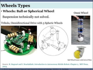
• Wheels: Ball or Spherical Wheel
Suspension technically not solved.
Source: R. Siegwart and I. Nourbakhsh. Introduction to Autonomous Mobile Robots. Chapter 2, MIT Press,
2004.
Tribolo, Omnidirectional Drive with 3 Spheric Wheels
Omni Wheel
Wheels Types
Ball Wheel Caster with Swivel Plate
- 38.
MUSES_SECRET: ORF-RE Project- © PAMI Research Group – University of Waterloo 38/22
38
L2, SPC418: Autonomous Vehicles Design and Control- Zewail City of Science and Technology - Fall 2016 © Dr. Alaa Khamis
MUSES_SECRET: ORF-RE Project - © PAMI Research Group – University of Waterloo
• Robot Locomotion
• Legged Mobile Robots (Walking Machines)
• Leg Configurations and Stability
• Wheeled Mobile Robots (Driving Robots)
• Wheels Types
• Wheel Arrangements
• Mobility Configurations
• Mobility, Steerability and Maneuverability
• Mobile Robot Kinematics
• Differential Drive Kinematics
• Summary
Outline
- 39.
MUSES_SECRET: ORF-RE Project- © PAMI Research Group – University of Waterloo 39/22
39
L2, SPC418: Autonomous Vehicles Design and Control- Zewail City of Science and Technology - Fall 2016 © Dr. Alaa Khamis
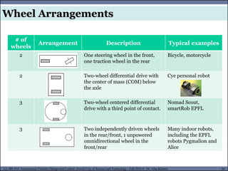
Wheel Arrangements
# of
wheels
Arrangement Description Typical examples
2 One steering wheel in the front,
one traction wheel in the rear
Bicycle, motorcycle
2 Two-wheel differential drive with
the center of mass (COM) below
the axle
Cye personal robot
3 Two-wheel centered differential
drive with a third point of contact.
Nomad Scout,
smartRob EPFL
3 Two independently driven wheels
in the rear/front, 1 unpowered
omnidirectional wheel in the
front/rear
Many indoor robots,
including the EPFL
robots Pygmalion and
Alice
- 40.
MUSES_SECRET: ORF-RE Project- © PAMI Research Group – University of Waterloo 40/22
40
L2, SPC418: Autonomous Vehicles Design and Control- Zewail City of Science and Technology - Fall 2016 © Dr. Alaa Khamis
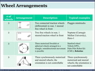
# of
wheels
Arrangement Description Typical examples
3 Two connected traction wheels
(differential) in rear, 1 steered
free wheel in front
Piaggio minitrucks
3 Two free wheels in rear, 1
steered traction wheel in front
Neptune (Carnegie
Mellon University),
Hero-1
3 Three motorized Swedish or
spherical wheels arranged in a
triangle; omnidirectional movement
is possible
Stanford wheel
Tribolo EPFL,
Palm Pilot Robot Kit
(CMU), Robotino
3 Three synchronously motorized
and steered wheels; the
orientation is not controllable
Three synchronously
motorized and steered
wheels; the orientation is
not controllable
Wheel Arrangements
- 41.
MUSES_SECRET: ORF-RE Project- © PAMI Research Group – University of Waterloo 41/22
41
L2, SPC418: Autonomous Vehicles Design and Control- Zewail City of Science and Technology - Fall 2016 © Dr. Alaa Khamis
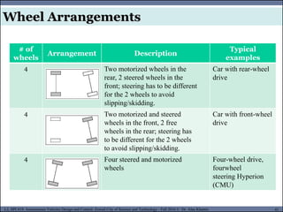
# of
wheels
Arrangement Description
Typical
examples
4 Two motorized wheels in the
rear, 2 steered wheels in the
front; steering has to be different
for the 2 wheels to avoid
slipping/skidding.
Car with rear-wheel
drive
4 Two motorized and steered
wheels in the front, 2 free
wheels in the rear; steering has
to be different for the 2 wheels
to avoid slipping/skidding.
Car with front-wheel
drive
4 Four steered and motorized
wheels
Four-wheel drive,
fourwheel
steering Hyperion
(CMU)
Wheel Arrangements
- 42.
MUSES_SECRET: ORF-RE Project- © PAMI Research Group – University of Waterloo 42/22
42
L2, SPC418: Autonomous Vehicles Design and Control- Zewail City of Science and Technology - Fall 2016 © Dr. Alaa Khamis
# of
wheels
Arrangement Description
Typical
examples
4 Two traction wheels (differential)
in rear/front, 2 omnidirectional
wheels in the front/rear.
Charlie (DMT-
EPFL)
4 Four omnidirectional wheels Carnegie Mellon
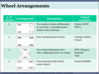
Uranus
4 Two-wheel differential drive
with 2 additional points of contact
EPFL Khepera,
Hyperbot
Chip
4 Four motorized and steered
castor wheels
Nomad XR4000
Wheel Arrangements
- 43.
MUSES_SECRET: ORF-RE Project- © PAMI Research Group – University of Waterloo 43/22
43
L2, SPC418: Autonomous Vehicles Design and Control- Zewail City of Science and Technology - Fall 2016 © Dr. Alaa Khamis
# of
wheels
Arrangement Description
Typical
examples
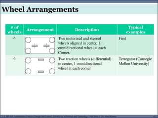
6 Two motorized and steered
wheels aligned in center, 1
omnidirectional wheel at each
Corner.
First
6 Two traction wheels (differential)
in center, 1 omnidirectional
wheel at each corner
Terregator (Carnegie
Mellon University)
Wheel Arrangements
- 44.
MUSES_SECRET: ORF-RE Project- © PAMI Research Group – University of Waterloo 44/22
44
L2, SPC418: Autonomous Vehicles Design and Control- Zewail City of Science and Technology - Fall 2016 © Dr. Alaa Khamis
Wheel Arrangements
- 45.
MUSES_SECRET: ORF-RE Project- © PAMI Research Group – University of Waterloo 45/22
45
L2, SPC418: Autonomous Vehicles Design and Control- Zewail City of Science and Technology - Fall 2016 © Dr. Alaa Khamis
MUSES_SECRET: ORF-RE Project - © PAMI Research Group – University of Waterloo
• Robot Locomotion
• Legged Mobile Robots (Walking Machines)
• Leg Configurations and Stability
• Wheeled Mobile Robots (Driving Robots)
• Wheels Types
• Wheel Arrangements
• Mobility Configurations
• Mobility, Steerability and Maneuverability
• Mobile Robot Kinematics
• Differential Drive Kinematics
• Summary
Outline
- 46.
MUSES_SECRET: ORF-RE Project- © PAMI Research Group – University of Waterloo 46/22
46
L2, SPC418: Autonomous Vehicles Design and Control- Zewail City of Science and Technology - Fall 2016 © Dr. Alaa Khamis
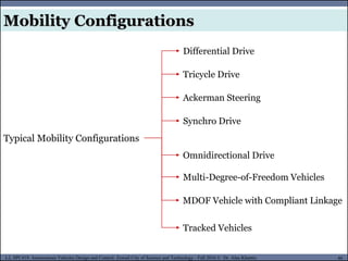
Typical Mobility Configurations
Differential Drive
Tricycle Drive
Ackerman Steering
Synchro Drive
Omnidirectional Drive
Multi-Degree-of-Freedom Vehicles
MDOF Vehicle with Compliant Linkage
Tracked Vehicles
Mobility Configurations
- 47.
MUSES_SECRET: ORF-RE Project- © PAMI Research Group – University of Waterloo 47/22
47
L2, SPC418: Autonomous Vehicles Design and Control- Zewail City of Science and Technology - Fall 2016 © Dr. Alaa Khamis
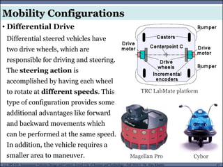
Magellan Pro
TRC LabMate platform
Cybor
Differential steered vehicles have
two drive wheels, which are
responsible for driving and steering.
The steering action is
accomplished by having each wheel
to rotate at different speeds. This
type of configuration provides some
additional advantages like forward
and backward movements which
can be performed at the same speed.
In addition, the vehicle requires a
smaller area to maneuver.
Mobility Configurations
• Differential Drive
- 48.
MUSES_SECRET: ORF-RE Project- © PAMI Research Group – University of Waterloo 48/22
48
L2, SPC418: Autonomous Vehicles Design and Control- Zewail City of Science and Technology - Fall 2016 © Dr. Alaa Khamis
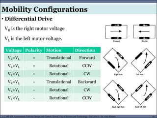
VR is the right motor voltage
VL is the left motor voltage.
Mobility Configurations
• Differential Drive
Voltage Polarity Motion Direction
VR=VL + Translational Forward
VR>VL + Rotational CCW
VR<VL + Rotational CW
VR=VL - Translational Backward
VR>VL - Rotational CW
VR<VL - Rotational CCW
- 49.
MUSES_SECRET: ORF-RE Project- © PAMI Research Group – University of Waterloo 49/22
49
L2, SPC418: Autonomous Vehicles Design and Control- Zewail City of Science and Technology - Fall 2016 © Dr. Alaa Khamis
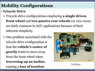
◊ Tricycle-drive configurations employing a single driven
front wheel and two passive rear wheels (or vice versa)
are fairly common in AGV applications because of their
inherent simplicity.
Mobility Configurations
• Tricycle Drive
bulldog2
◊ One problem associated with the
tricycle-drive configuration is
that the vehicle’s center of
gravity tends to move away
from the front wheel when
traversing up an incline,
causing a loss of traction.
- 50.
MUSES_SECRET: ORF-RE Project- © PAMI Research Group – University of Waterloo 50/22
50
L2, SPC418: Autonomous Vehicles Design and Control- Zewail City of Science and Technology - Fall 2016 © Dr. Alaa Khamis
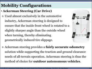
◊ Used almost exclusively in the automotive
industry, Ackerman steering is designed to
ensure that the inside front wheel is rotated to a
slightly sharper angle than the outside wheel
when turning, thereby eliminating
geometrically induced tire slippage.
Mobility Configurations
• Ackerman Steering (Car Drive)
◊ Ackerman steering provides a fairly accurate odometry
solution while supporting the traction and ground clearance
needs of all-terrain operation. Ackerman steering is thus the
method of choice for outdoor autonomous vehicles.
- 51.
MUSES_SECRET: ORF-RE Project- © PAMI Research Group – University of Waterloo 51/22
51
L2, SPC418: Autonomous Vehicles Design and Control- Zewail City of Science and Technology - Fall 2016 © Dr. Alaa Khamis
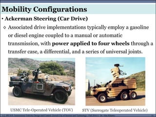
◊ Associated drive implementations typically employ a gasoline
or diesel engine coupled to a manual or automatic
transmission, with power applied to four wheels through a
transfer case, a differential, and a series of universal joints.
Mobility Configurations
• Ackerman Steering (Car Drive)
USMC Tele-Operated Vehicle (TOV) STV (Surrogate Teleoperated Vehicle)
- 52.
MUSES_SECRET: ORF-RE Project- © PAMI Research Group – University of Waterloo 52/22
52
L2, SPC418: Autonomous Vehicles Design and Control- Zewail City of Science and Technology - Fall 2016 © Dr. Alaa Khamis
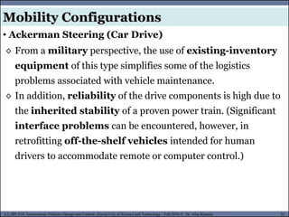
◊ From a military perspective, the use of existing-inventory
equipment of this type simplifies some of the logistics
problems associated with vehicle maintenance.
◊ In addition, reliability of the drive components is high due to
the inherited stability of a proven power train. (Significant
interface problems can be encountered, however, in
retrofitting off-the-shelf vehicles intended for human
drivers to accommodate remote or computer control.)
Mobility Configurations
• Ackerman Steering (Car Drive)
- 53.
MUSES_SECRET: ORF-RE Project- © PAMI Research Group – University of Waterloo 53/22
53
L2, SPC418: Autonomous Vehicles Design and Control- Zewail City of Science and Technology - Fall 2016 © Dr. Alaa Khamis
Mobility Configurations
• Synchro Drive
Synchro drive
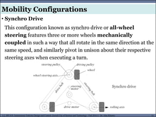
This configuration known as synchro drive or all-wheel
steering features three or more wheels mechanically
coupled in such a way that all rotate in the same direction at the
same speed, and similarly pivot in unison about their respective
steering axes when executing a turn.
- 54.
MUSES_SECRET: ORF-RE Project- © PAMI Research Group – University of Waterloo 54/22
54
L2, SPC418: Autonomous Vehicles Design and Control- Zewail City of Science and Technology - Fall 2016 © Dr. Alaa Khamis
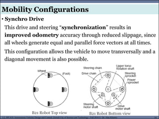
This drive and steering “synchronization” results in
improved odometry accuracy through reduced slippage, since
all wheels generate equal and parallel force vectors at all times.
This configuration allows the vehicle to move transversally and a
diagonal movement is also possible.
B21 Robot Top view
Mobility Configurations
• Synchro Drive
B21 Robot Bottom view
- 55.
MUSES_SECRET: ORF-RE Project- © PAMI Research Group – University of Waterloo 55/22
55
L2, SPC418: Autonomous Vehicles Design and Control- Zewail City of Science and Technology - Fall 2016 © Dr. Alaa Khamis
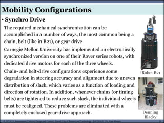
The required mechanical synchronization can be
accomplished in a number of ways, the most common being a
chain, belt (like in B21), or gear drive.
Carnegie Mellon University has implemented an electronically
synchronized version on one of their Rover series robots, with
dedicated drive motors for each of the three wheels.
Chain- and belt-drive configurations experience some
degradation in steering accuracy and alignment due to uneven
distribution of slack, which varies as a function of loading and
direction of rotation. In addition, whenever chains (or timing
belts) are tightened to reduce such slack, the individual wheels
must be realigned. These problems are eliminated with a
completely enclosed gear-drive approach.
iRobot B21
Denning
Blacky
Mobility Configurations
• Synchro Drive
- 56.
MUSES_SECRET: ORF-RE Project- © PAMI Research Group – University of Waterloo 56/22
56
L2, SPC418: Autonomous Vehicles Design and Control- Zewail City of Science and Technology - Fall 2016 © Dr. Alaa Khamis
In a synchronous drive robot, each wheel is capable of being
driven and steered.
Typical configurations
◊ Three steered wheels arranged as vertices of an equilateral
◊ Triangle often surmounted by a cylindrical platform
◊ All the wheels turn and drive in unison
This leads to a holonomic behavior.
Mobility Configurations
• Synchro Drive
- 57.
MUSES_SECRET: ORF-RE Project- © PAMI Research Group – University of Waterloo 57/22
57
L2, SPC418: Autonomous Vehicles Design and Control- Zewail City of Science and Technology - Fall 2016 © Dr. Alaa Khamis
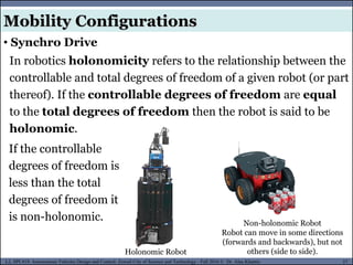
Non-holonomic Robot
Robot can move in some directions
(forwards and backwards), but not
others (side to side).
Holonomic Robot
In robotics holonomicity refers to the relationship between the
controllable and total degrees of freedom of a given robot (or part
thereof). If the controllable degrees of freedom are equal
to the total degrees of freedom then the robot is said to be
holonomic.
If the controllable
degrees of freedom is
less than the total
degrees of freedom it
is non-holonomic.
Mobility Configurations
• Synchro Drive
- 58.
MUSES_SECRET: ORF-RE Project- © PAMI Research Group – University of Waterloo 58/22
58
L2, SPC418: Autonomous Vehicles Design and Control- Zewail City of Science and Technology - Fall 2016 © Dr. Alaa Khamis
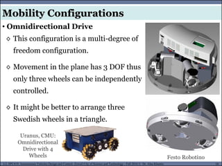
◊ This configuration is a multi-degree of
freedom configuration.
◊ Movement in the plane has 3 DOF thus
only three wheels can be independently
controlled.
◊ It might be better to arrange three
Swedish wheels in a triangle.
Mobility Configurations
• Omnidirectional Drive
Festo Robotino
Uranus, CMU:
Omnidirectional
Drive with 4
Wheels
- 59.
MUSES_SECRET: ORF-RE Project- © PAMI Research Group – University of Waterloo 59/22
59
L2, SPC418: Autonomous Vehicles Design and Control- Zewail City of Science and Technology - Fall 2016 © Dr. Alaa Khamis
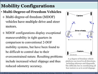
◊ Multi-degree-of-freedom (MDOF)
vehicles have multiple drive and steer
motors.
◊ MDOF configurations display exceptional
maneuverability in tight quarters in
comparison to conventional 2-DOF
mobility systems, but have been found to
be difficult to control due to their
overconstrained nature. Resulting problems
include increased wheel slippage and thus
reduced odometry accuracy.
A 4-degree-of-freedom vehicle
platform can travel in all directions,
including sideways and diagonally.
The difficulty lies in coordinating all
four motors so as to avoid slippage.
Mobility Configurations
• Multi-Degree-of-Freedom Vehicles
- 60.
MUSES_SECRET: ORF-RE Project- © PAMI Research Group – University of Waterloo 60/22
60
L2, SPC418: Autonomous Vehicles Design and Control- Zewail City of Science and Technology - Fall 2016 © Dr. Alaa Khamis
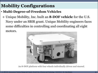
◊ Unique Mobility, Inc. built an 8-DOF vehicle for the U.S.
Navy under an SBIR grant. Unique Mobility engineers faces
some difficulties in controlling and coordinating all eight
motors.
An 8-DOF platform with four wheels individually driven and steered.
Mobility Configurations
• Multi-Degree-of-Freedom Vehicles
- 61.
MUSES_SECRET: ORF-RE Project- © PAMI Research Group – University of Waterloo 61/22
61
L2, SPC418: Autonomous Vehicles Design and Control- Zewail City of Science and Technology - Fall 2016 © Dr. Alaa Khamis
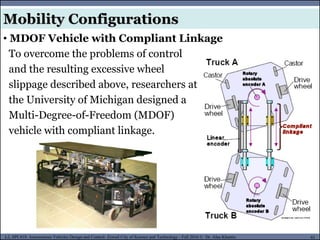
To overcome the problems of control
and the resulting excessive wheel
slippage described above, researchers at
the University of Michigan designed a
Multi-Degree-of-Freedom (MDOF)
vehicle with compliant linkage.
Mobility Configurations
• MDOF Vehicle with Compliant Linkage
- 62.
MUSES_SECRET: ORF-RE Project- © PAMI Research Group – University of Waterloo 62/22
62
L2, SPC418: Autonomous Vehicles Design and Control- Zewail City of Science and Technology - Fall 2016 © Dr. Alaa Khamis
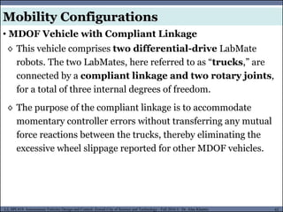
◊ This vehicle comprises two differential-drive LabMate
robots. The two LabMates, here referred to as “trucks,” are
connected by a compliant linkage and two rotary joints,
for a total of three internal degrees of freedom.
◊ The purpose of the compliant linkage is to accommodate
momentary controller errors without transferring any mutual
force reactions between the trucks, thereby eliminating the
excessive wheel slippage reported for other MDOF vehicles.
Mobility Configurations
• MDOF Vehicle with Compliant Linkage
- 63.
MUSES_SECRET: ORF-RE Project- © PAMI Research Group – University of Waterloo 63/22
63
L2, SPC418: Autonomous Vehicles Design and Control- Zewail City of Science and Technology - Fall 2016 © Dr. Alaa Khamis
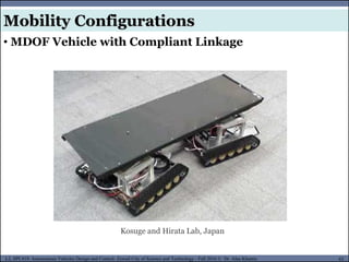
Kosuge and Hirata Lab, Japan
Mobility Configurations
• MDOF Vehicle with Compliant Linkage
- 64.
MUSES_SECRET: ORF-RE Project- © PAMI Research Group – University of Waterloo 64/22
64
L2, SPC418: Autonomous Vehicles Design and Control- Zewail City of Science and Technology - Fall 2016 © Dr. Alaa Khamis
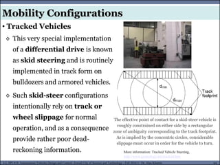
◊ This very special implementation
of a differential drive is known
as skid steering and is routinely
implemented in track form on
bulldozers and armored vehicles.
◊ Such skid-steer configurations
intentionally rely on track or
wheel slippage for normal
operation, and as a consequence
provide rather poor dead-
reckoning information. More information: Tracked Vehicle Steering,
http://www.gizmology.net/tracked.htm
The effective point of contact for a skid-steer vehicle is
roughly constrained on either side by a rectangular
zone of ambiguity corresponding to the track footprint.
As is implied by the concentric circles, considerable
slippage must occur in order for the vehicle to turn.
Mobility Configurations
• Tracked Vehicles
- 65.
MUSES_SECRET: ORF-RE Project- © PAMI Research Group – University of Waterloo 65/22
65
L2, SPC418: Autonomous Vehicles Design and Control- Zewail City of Science and Technology - Fall 2016 © Dr. Alaa Khamis
Mobility Configurations
• Tracked Vehicles
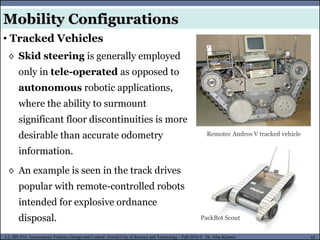
◊ Skid steering is generally employed
only in tele-operated as opposed to
autonomous robotic applications,
where the ability to surmount
significant floor discontinuities is more
desirable than accurate odometry
information.
◊ An example is seen in the track drives
popular with remote-controlled robots
intended for explosive ordnance
disposal. PackBot Scout
Remotec Andros V tracked vehicle
- 66.
MUSES_SECRET: ORF-RE Project- © PAMI Research Group – University of Waterloo 66/22
66
L2, SPC418: Autonomous Vehicles Design and Control- Zewail City of Science and Technology - Fall 2016 © Dr. Alaa Khamis
Mobility Configurations
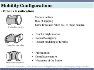
• Other classification
• Smooth motion
• Risk of slipping
• Some times use roller-ball to make balance
Bi-wheel type robot
Omnidirectional robot
Caterpillar type robot
• Exact straight motion
• Robust to slipping
• Inexact modeling of turning
• Free motion
• Complex structure
• Weakness of the frame
Source: Prof. Jizhong Xiao, “Mobile Robot Locomotion,” Department of Electrical Engineering City College of New York.
- 67.
MUSES_SECRET: ORF-RE Project- © PAMI Research Group – University of Waterloo 67/22
67
L2, SPC418: Autonomous Vehicles Design and Control- Zewail City of Science and Technology - Fall 2016 © Dr. Alaa Khamis
MUSES_SECRET: ORF-RE Project - © PAMI Research Group – University of Waterloo
• Robot Locomotion
• Legged Mobile Robots (Walking Machines)
• Leg Configurations and Stability
• Wheeled Mobile Robots (Driving Robots)
• Wheels Types
• Wheel Arrangements
• Mobility Configurations
• Mobility, Steerability and Maneuverability
• Mobile Robot Kinematics
• Differential Drive Kinematics
• Summary
Outline
- 68.
MUSES_SECRET: ORF-RE Project- © PAMI Research Group – University of Waterloo 68/22
68
L2, SPC418: Autonomous Vehicles Design and Control- Zewail City of Science and Technology - Fall 2016 © Dr. Alaa Khamis
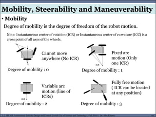
Mobility, Steerability and Maneuverability
• Mobility
Degree of mobility is the degree of freedom of the robot motion.
Degree of mobility : 0
Degree of mobility : 2 Degree of mobility : 3
Degree of mobility : 1
Cannot move
anywhere (No ICR)
Fixed arc
motion (Only
one ICR)
Variable arc
motion (line of
ICRs)
Fully free motion
( ICR can be located
at any position)
Note: Instantaneous center of rotation (ICR) or Instantaneous center of curvature (ICC) is a
cross point of all axes of the wheels.
- 69.
MUSES_SECRET: ORF-RE Project- © PAMI Research Group – University of Waterloo 69/22
69
L2, SPC418: Autonomous Vehicles Design and Control- Zewail City of Science and Technology - Fall 2016 © Dr. Alaa Khamis
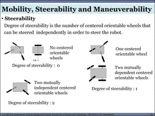
• Steerability
Degree of steerability is the number of centered orientable wheels that
can be steered independently in order to steer the robot.
Degree of steerability : 0
Degree of steerability : 2
Degree of steerability : 1
No centered
orientable
wheels
One centered
orientable wheel
Two mutually
dependent centered
orientable wheels
Two mutually
independent centered
orientable wheels
Mobility, Steerability and Maneuverability
- 70.
MUSES_SECRET: ORF-RE Project- © PAMI Research Group – University of Waterloo 70/22
70
L2, SPC418: Autonomous Vehicles Design and Control- Zewail City of Science and Technology - Fall 2016 © Dr. Alaa Khamis
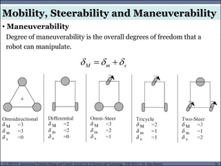
• Maneuverability
Degree of maneuverability is the overall degrees of freedom that a
robot can manipulate.
s
m
M
Mobility, Steerability and Maneuverability
- 71.
MUSES_SECRET: ORF-RE Project- © PAMI Research Group – University of Waterloo 71/22
71
L2, SPC418: Autonomous Vehicles Design and Control- Zewail City of Science and Technology - Fall 2016 © Dr. Alaa Khamis
MUSES_SECRET: ORF-RE Project - © PAMI Research Group – University of Waterloo
• Robot Locomotion
• Legged Mobile Robots (Walking Machines)
• Leg Configurations and Stability
• Wheeled Mobile Robots (Driving Robots)
• Wheels Types
• Wheel Arrangements
• Mobility Configurations
• Mobility, Steerability and Maneuverability
• Mobile Robot Kinematics
• Differential Drive Kinematics
• Summary
Outline
- 72.
MUSES_SECRET: ORF-RE Project- © PAMI Research Group – University of Waterloo 72/22
72
L2, SPC418: Autonomous Vehicles Design and Control- Zewail City of Science and Technology - Fall 2016 © Dr. Alaa Khamis
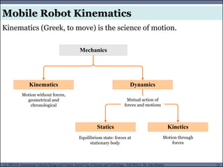
Mobile Robot Kinematics
Kinematics
Mechanics
Dynamics
Statics Kinetics
Motion without forces,
geometrical and
chronological
Mutual action of
forces and motions
Motion through
forces
Equilibrium state: forces at
stationary body
Kinematics (Greek, to move) is the science of motion.
- 73.
MUSES_SECRET: ORF-RE Project- © PAMI Research Group – University of Waterloo 73/22
73
L2, SPC418: Autonomous Vehicles Design and Control- Zewail City of Science and Technology - Fall 2016 © Dr. Alaa Khamis
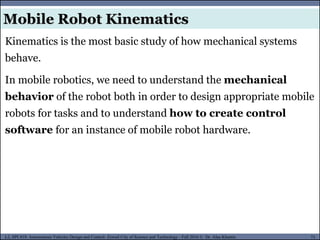
Kinematics is the most basic study of how mechanical systems
behave.
In mobile robotics, we need to understand the mechanical
behavior of the robot both in order to design appropriate mobile
robots for tasks and to understand how to create control
software for an instance of mobile robot hardware.
Mobile Robot Kinematics
- 74.
MUSES_SECRET: ORF-RE Project- © PAMI Research Group – University of Waterloo 74/22
74
L2, SPC418: Autonomous Vehicles Design and Control- Zewail City of Science and Technology - Fall 2016 © Dr. Alaa Khamis
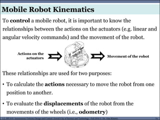
To control a mobile robot, it is important to know the
relationships between the actions on the actuators (e.g. linear and
angular velocity commands) and the movement of the robot.
Actions on the
actuators Movement of the robot
These relationships are used for two purposes:
• To calculate the actions necessary to move the robot from one
position to another.
• To evaluate the displacements of the robot from the
movements of the wheels (i.e., odometry)
Mobile Robot Kinematics
- 75.
MUSES_SECRET: ORF-RE Project- © PAMI Research Group – University of Waterloo 75/22
75
L2, SPC418: Autonomous Vehicles Design and Control- Zewail City of Science and Technology - Fall 2016 © Dr. Alaa Khamis
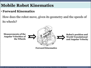
How does the robot move, given its geometry and the speeds of
its wheels?
Measurements of the
Angular Velocities of
the Wheels
Robot’s position and
World Translational
and Angular Velocity
Forward Kinematics
• Forward Kinematics
Mobile Robot Kinematics
- 76.
MUSES_SECRET: ORF-RE Project- © PAMI Research Group – University of Waterloo 76/22
76
L2, SPC418: Autonomous Vehicles Design and Control- Zewail City of Science and Technology - Fall 2016 © Dr. Alaa Khamis
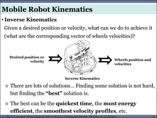
Given a desired position or velocity, what can we do to achieve it
(what are the corresponding vector of wheels velocities)?
Desired position or
velocity Wheels position and
velocities
Inverse Kinematics
• Inverse Kinematics
◊ There are lots of solutions… Finding some solution is not hard,
but finding the “best” solution is.
◊ The best can be the quickest time, the most energy
efficient, the smoothest velocity profiles, etc.
Mobile Robot Kinematics
- 77.
MUSES_SECRET: ORF-RE Project- © PAMI Research Group – University of Waterloo 77/22
77
L2, SPC418: Autonomous Vehicles Design and Control- Zewail City of Science and Technology - Fall 2016 © Dr. Alaa Khamis
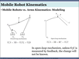
Open-loop mechanism
Closed-loop mechanism
In open-loop mechanism, unless O1C is
measured by feedback, the change will
not be known.
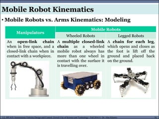
• Mobile Robots vs. Arms Kinematics: Modeling
Mobile Robot Kinematics
- 78.
MUSES_SECRET: ORF-RE Project- © PAMI Research Group – University of Waterloo 78/22
78
L2, SPC418: Autonomous Vehicles Design and Control- Zewail City of Science and Technology - Fall 2016 © Dr. Alaa Khamis
Manipulators
Mobile Robots
Wheeled Robots Legged Robots
An open-link chain
when in free space, and a
closed-link chain when in
contact with a workpiece.
A multiple closed-link
chain as a wheeled
mobile robot always has
more than one wheel in
contact with the surface it
is travelling over.
A chain for each leg,
which opens and closes as
the foot is lift off the
ground and placed back
on the ground.
• Mobile Robots vs. Arms Kinematics: Modeling
Mobile Robot Kinematics
- 79.
MUSES_SECRET: ORF-RE Project- © PAMI Research Group – University of Waterloo 79/22
79
L2, SPC418: Autonomous Vehicles Design and Control- Zewail City of Science and Technology - Fall 2016 © Dr. Alaa Khamis
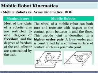
Manipulators Mobile Robots
Most of the joints
of a robotic arm
are restricted to
one degree of
freedom, and the
degrees of freedom
of the end-effector
are constrained by
the task.
The wheel of a mobile robot can both
turn and translate with respect to the
contact point between it and the floor.
This pseudo joint is described as a
higher order pair. A lower-order pair
is constrained by a common surface of
contact, such as a prismatic joint.
• Mobile Robots vs. Arms Kinematics: DOF
Mobile Robot Kinematics
- 80.
MUSES_SECRET: ORF-RE Project- © PAMI Research Group – University of Waterloo 80/22
80
L2, SPC418: Autonomous Vehicles Design and Control- Zewail City of Science and Technology - Fall 2016 © Dr. Alaa Khamis
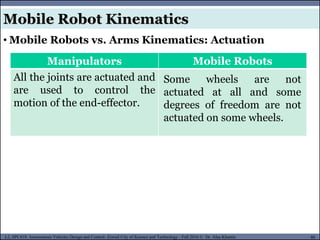
Manipulators Mobile Robots
All the joints are actuated and
are used to control the
motion of the end-effector.
Some wheels are not
actuated at all and some
degrees of freedom are not
actuated on some wheels.
• Mobile Robots vs. Arms Kinematics: Actuation
Mobile Robot Kinematics
- 81.
MUSES_SECRET: ORF-RE Project- © PAMI Research Group – University of Waterloo 81/22
81
L2, SPC418: Autonomous Vehicles Design and Control- Zewail City of Science and Technology - Fall 2016 © Dr. Alaa Khamis
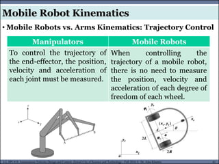
Manipulators Mobile Robots
To control the trajectory of
the end-effector, the position,
velocity and acceleration of
each joint must be measured.
When controlling the
trajectory of a mobile robot,
there is no need to measure
the position, velocity and
acceleration of each degree of
freedom of each wheel.
• Mobile Robots vs. Arms Kinematics: Trajectory Control
Mobile Robot Kinematics
- 82.
MUSES_SECRET: ORF-RE Project- © PAMI Research Group – University of Waterloo 82/22
82
L2, SPC418: Autonomous Vehicles Design and Control- Zewail City of Science and Technology - Fall 2016 © Dr. Alaa Khamis
MUSES_SECRET: ORF-RE Project - © PAMI Research Group – University of Waterloo
• Robot Locomotion
• Legged Mobile Robots (Walking Machines)
• Leg Configurations and Stability
• Wheeled Mobile Robots (Driving Robots)
• Wheels Types
• Wheel Arrangements
• Mobility Configurations
• Mobility, Steerability and Maneuverability
• Mobile Robot Kinematics
• Differential Drive Kinematics
• Summary
Outline
- 83.
MUSES_SECRET: ORF-RE Project- © PAMI Research Group – University of Waterloo 83/22
83
L2, SPC418: Autonomous Vehicles Design and Control- Zewail City of Science and Technology - Fall 2016 © Dr. Alaa Khamis
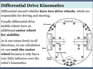
Differential steered vehicles have two drive wheels, which are
responsible for driving and steering.
Usually differential drive
mobile robots have an
additional castor wheel
for stability.
As it can rotate freely in all
directions, in our calculation
we can omit the castor
wheel because it only has a
very little influence over the
robot’s kinematics.
Differential Drive Kinematics
- 84.
MUSES_SECRET: ORF-RE Project- © PAMI Research Group – University of Waterloo 84/22
84
L2, SPC418: Autonomous Vehicles Design and Control- Zewail City of Science and Technology - Fall 2016 © Dr. Alaa Khamis
Differential Drive Kinematics
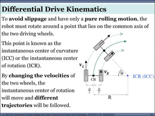
To avoid slippage and have only a pure rolling motion, the
robot must rotate around a point that lies on the common axis of
the two driving wheels.
This point is known as the
instantaneous center of curvature
(ICC) or the instantaneous center
of rotation (ICR).
By changing the velocities of
the two wheels, the
instantaneous center of rotation
will move and different
trajectories will be followed.
- 85.
MUSES_SECRET: ORF-RE Project- © PAMI Research Group – University of Waterloo 85/22
85
L2, SPC418: Autonomous Vehicles Design and Control- Zewail City of Science and Technology - Fall 2016 © Dr. Alaa Khamis
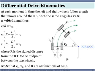
At each moment in time the left and right wheels follow a path
that moves around the ICR with the same angular rate
=d/dt, and thus:
CR
v
R
.
where R is the signed distance
from the ICC to the midpoint
between the two wheels.
Note that vL, vR, and R are all functions of time.
Differential Drive Kinematics
R
L
v
D
R
v
D
R
2
.
2
.
- 86.
MUSES_SECRET: ORF-RE Project- © PAMI Research Group – University of Waterloo 86/22
86
L2, SPC418: Autonomous Vehicles Design and Control- Zewail City of Science and Technology - Fall 2016 © Dr. Alaa Khamis
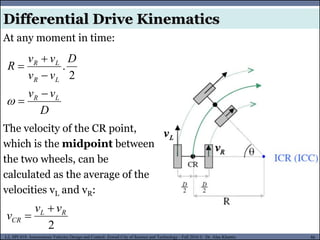
At any moment in time:
D
v
v
D
v
v
v
v
R
L
R
L
R
L
R
2
.
The velocity of the CR point,
which is the midpoint between
the two wheels, can be
calculated as the average of the
velocities vL and vR:
2
R
L
CR
v
v
v
Differential Drive Kinematics
- 87.
MUSES_SECRET: ORF-RE Project- © PAMI Research Group – University of Waterloo 87/22
87
L2, SPC418: Autonomous Vehicles Design and Control- Zewail City of Science and Technology - Fall 2016 © Dr. Alaa Khamis
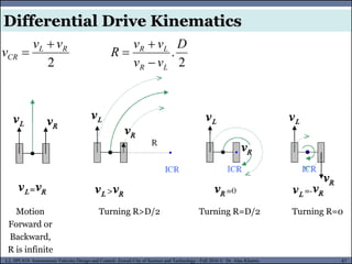
2
R
L
CR
v
v
v
Motion
Forward or
Backward,
R is infinite
Turning R>D/2 Turning R=D/2 Turning R=0
2
.
D
v
v
v
v
R
L
R
L
R
Differential Drive Kinematics
- 88.
MUSES_SECRET: ORF-RE Project- © PAMI Research Group – University of Waterloo 88/22
88
L2, SPC418: Autonomous Vehicles Design and Control- Zewail City of Science and Technology - Fall 2016 © Dr. Alaa Khamis
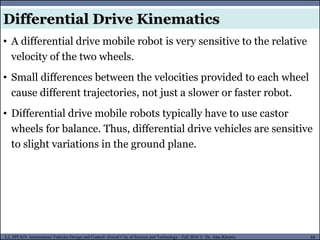
• A differential drive mobile robot is very sensitive to the relative
velocity of the two wheels.
• Small differences between the velocities provided to each wheel
cause different trajectories, not just a slower or faster robot.
• Differential drive mobile robots typically have to use castor
wheels for balance. Thus, differential drive vehicles are sensitive
to slight variations in the ground plane.
Differential Drive Kinematics
- 89.
MUSES_SECRET: ORF-RE Project- © PAMI Research Group – University of Waterloo 89/22
89
L2, SPC418: Autonomous Vehicles Design and Control- Zewail City of Science and Technology - Fall 2016 © Dr. Alaa Khamis
MUSES_SECRET: ORF-RE Project - © PAMI Research Group – University of Waterloo
• Robot Locomotion
• Legged Mobile Robots (Walking Machines)
• Leg Configurations and Stability
• Wheeled Mobile Robots (Driving Robots)
• Wheels Types
• Wheel Arrangements
• Mobility Configurations
• Mobility, Steerability and Maneuverability
• Mobile Robot Kinematics
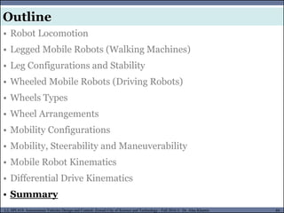
• Differential Drive Kinematics
• Summary
Outline
- 90.
MUSES_SECRET: ORF-RE Project- © PAMI Research Group – University of Waterloo 90/22
90
L2, SPC418: Autonomous Vehicles Design and Control- Zewail City of Science and Technology - Fall 2016 © Dr. Alaa Khamis
Summary
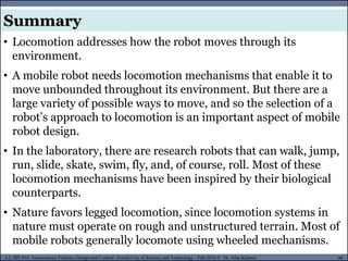
• Locomotion addresses how the robot moves through its
environment.
• A mobile robot needs locomotion mechanisms that enable it to
move unbounded throughout its environment. But there are a
large variety of possible ways to move, and so the selection of a
robot’s approach to locomotion is an important aspect of mobile
robot design.
• In the laboratory, there are research robots that can walk, jump,
run, slide, skate, swim, fly, and, of course, roll. Most of these
locomotion mechanisms have been inspired by their biological
counterparts.
• Nature favors legged locomotion, since locomotion systems in
nature must operate on rough and unstructured terrain. Most of
mobile robots generally locomote using wheeled mechanisms.
- 91.
MUSES_SECRET: ORF-RE Project- © PAMI Research Group – University of Waterloo 91/22
91
L2, SPC418: Autonomous Vehicles Design and Control- Zewail City of Science and Technology - Fall 2016 © Dr. Alaa Khamis
Summary
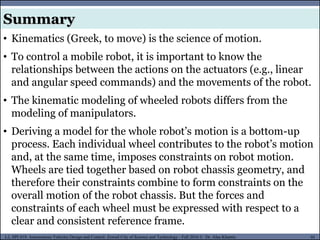
• Kinematics (Greek, to move) is the science of motion.
• To control a mobile robot, it is important to know the
relationships between the actions on the actuators (e.g., linear
and angular speed commands) and the movements of the robot.
• The kinematic modeling of wheeled robots differs from the
modeling of manipulators.
• Deriving a model for the whole robot’s motion is a bottom-up
process. Each individual wheel contributes to the robot’s motion
and, at the same time, imposes constraints on robot motion.
Wheels are tied together based on robot chassis geometry, and
therefore their constraints combine to form constraints on the
overall motion of the robot chassis. But the forces and
constraints of each wheel must be expressed with respect to a
clear and consistent reference frame.
- 92.
MUSES_SECRET: ORF-RE Project- © PAMI Research Group – University of Waterloo 92/22
92
L2, SPC418: Autonomous Vehicles Design and Control- Zewail City of Science and Technology - Fall 2016 © Dr. Alaa Khamis
For reading
• Dimitrios Apostolopoulos. Systematic Configuration of Robotic
Locomotion. Robotics Institute, Carnegie Mellon University,
1996.
• Thomas THÜER. Mobility evaluation of wheeled all-terrain
robots Metrics and application: Metrics and application. PhD
Thesis, ETH Zurich, 2009.
• Roland Siegwart. Robots for Space: Exploration Robot
Examples.
• Working Model 2D (WM2D) Tool
• Motor Sizing Calculations, Technical Reference