This document provides information about various sensors and integrated circuits (ICs), including their technologies and applications. It discusses photo sensors, IR sensors, motor driver ICs, and soil moisture sensors. It describes how photo sensors work using light sources, receivers and signal converters to detect changes in light intensity. It outlines different sensing modes for photo sensors including diffused, retro-reflective, and thru-beam. It also discusses integrated circuits, how they are made and their revolutionary impact on electronics and modern society.


![11
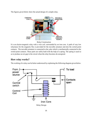
Construction
Infrared radiation enters through the front of the sensor, known as the 'sensor face'. At the core of
a PIR sensor is a solid state sensor or set of sensors, made from pyroelectric materials—materials
which generate energy when exposed to heat. Typically, the sensors are approximately 1/4 inch
square (40 mm2
), and take the form of a thin film. Materials commonly used in PIR sensors
include gallium nitride (GaN), caesium nitrate (CsNO3), polyvinyl fluorides, derivatives
of phenylpyridine, and cobalt phthalocyanine. The sensor is often manufactured as part of
an integrated circuit.
PIR-based motion detector
A PIR motion detector used to control an outdoor, automatic light.
A PIR-based motion detector is used to sense movement of people, animals, or other objects. They
are commonly used in burglar alarms and automatically-activated lighting systems. They are
commonly called simply "PIR", or sometimes "PID", for "passive infrared detector".
Operation
An individual PIR sensor detects changes in the amount of infrared radiation impinging upon it,
which varies depending on the temperature and surface characteristics of the objects in front of the
sensor.[2]
When an object, such as a human, passes in front of the background, such as a wall, the
temperature at that point in the sensor's field of view will rise from room temperature to body
temperature, and then back again. The sensor converts the resulting change in the incoming
infrared radiation into a change in the output voltage, and this triggers the detection. Objects of
similar temperature but different surface characteristics may also have a different infrared emission
pattern, and thus moving them with respect to the background may trigger the detector as well.
PIRs come in many configurations for a wide variety of applications. The most common models
have numerous Fresnel lenses or mirror segments, an effective range of about ten meters (thirty
feet), and a field of view less than 180 degrees. Models with wider fields of view, including 360
degrees, are available—typically designed to mount on a ceiling. Some larger PIRs are made with
single segment mirrors and can sense changes in infrared energy over thirty meters (one hundred
feet) away from the PIR. There are also PIRs designed with reversible orientation mirrors which](https://image.slidesharecdn.com/sensorsandics-170315090306/85/Sensors-and-ics-11-320.jpg)


![PHOTO ELECTRIC SENSORS [Autosaved].pptx](https://cdn.slidesharecdn.com/ss_thumbnails/photoelectricsensorsautosaved-230122195642-139c3524-thumbnail.jpg?width=640&height=640&fit=bounds)