Downloaded 64 times


![23
REFERENCES
[1] Rouhollah Soltani Goharrizi, Fazlollah Soltani and Bahador Abolpour, 2013, “Study of
Geosynthetic Clay Liner Layers Effect on Decreasing Soil Pollution in the Bed of Sanitary
Land Fills,” published in International Journal of Water Resources and Environmental
Engineering, DOI: 10.5897/IJWREE2013.0421, Vol 5(8), August
[2] Mochamad Arief Budihardjo, Amin Chegenizadeh and Hamid Nikraz, 2012,
“Geosynthetic Clay Liner as Landfill’s Leachate Barrier,”published in International
Conference on Civil and Architectural applications (ICCAA), December
[3] Jian Yu1, Jigang Shi1 and Han Liu2, 2012, “Case Study on Application of Geosynthetic
Clay Liner in Canal Lining in Hetao Irrigation Area,” Inner Mongolia, ICID 21st
International Congress on Irrigation and Drainage,15-23 October
[4] P. Phillips and M. Eberle , The use of Geosynthetic Clay Liners (GCL's) in containment
applications, International journal Geofabrics Australasia Pty Ltd, Australia.
[5] Y.Liua,1 , A. Bouazzab,* , W.P.Gatesb,2 , R.K. Rowec,3 , 2015, “Hydraulic Perfomance of
Geosynthetic Clay Liners,” Geotextile and Geomembranes
[6] Bouazza, A. and Bowders, J. (2009). “GCLs in Waste Containment Applications,” Taylor
Francis, U.K. (in press).
[7] Rouf, M.A , Bouazza, A, Singh, R.M , Gates, W.P , Rowe, R.K, 2015, “Gas Diffusion
Coefficient and Gas Permeability of an Unsaturated Geosynthetic Clay Liner,” published in
Geosynthetics Conference 2015, February](https://image.slidesharecdn.com/seminarreport-161022180409/85/Seminar-report-23-320.jpg)


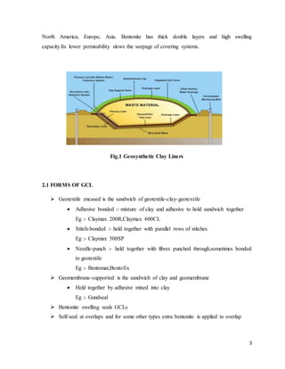
Geosynthetic clay liners (GCLs) are materials used to line landfills that incorporate a layer of bentonite clay between two layers of geosynthetic fabric. The low permeability of the bentonite clay slows the rate of liquid seepage out of the landfill. GCLs are fast and easy to install, have very low hydraulic conductivity, and can self-repair tears due to the swelling properties of bentonite. They are increasingly used as barriers in mining and industrial facilities due to their ability to form a hydraulic barrier with low permeability. GCLs consist of bentonite clay bonded between one or more layers of geosynthetic material such as geotextiles or geomembranes. The


