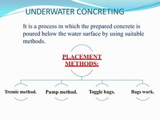
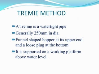
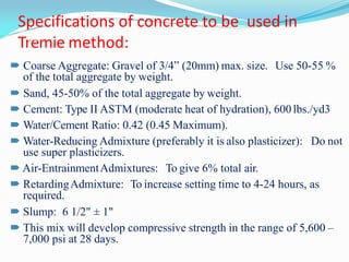
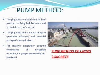
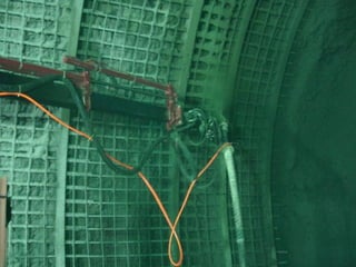
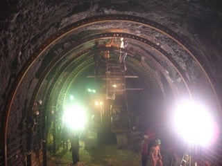
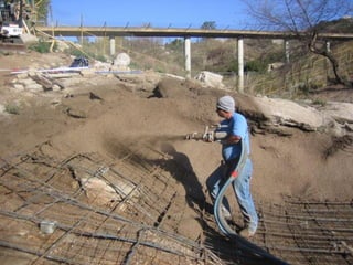
During the construction of brides , dams or any other
structure where the foundation part of the structure is
most likely to lie underwater, we have to opt for
underwater construction
Construction in water poses many difficulties especially
in the places where there the depth is considerable.
During underwater construction our main objective is to
create dry and water free environment for working in such
a manner that the structural stability of the structure is not
compromised.
3
UNDERWATER CONCRETING
Tremie method. Pump method. Toggle bags. Bags work.
It is a process in which the prepared concrete is
poured below the water surface by using suitable
methods.
PLACEMENT
METHODS:
17
TREMIE METHOD
A Tremie is a watertightpipe
Generally 250mm in dia.
Funnel shaped hopper at its upper end
and a loose plug at the bottom.
It is supported on a working platform
above water level.
18
Laying of concrete by using Tremie
Basic principle behind Method
of underwater concreting -
Tremie method
Method of underwater
concreting— Tremie
method (inside view)
Specifications of concrete to be used in
Tremie method:
20
 Coarse Aggregate: Gravel of 3/4” (20mm) max. size. Use 50-55 %
of the total aggregate by weight.
 Sand, 45-50% of the total aggregate by weight.
 Cement: Type II ASTM (moderate heat of hydration), 600 lbs./yd3
 Water/Cement Ratio: 0.42 (0.45 Maximum).
 Water-Reducing Admixture (preferably it is also plasticizer): Do not
use super plasticizers.
 Air-EntrainmentAdmixtures: To give 6% total air.
 RetardingAdmixture: To increase setting time to 4-24 hours, as
required.
 Slump: 6 1/2" ± 1"
 This mix will develop compressive strength in the range of 5,600 –
7,000 psi at 28 days.
PUMP METHOD:
 Pumping concrete directly into its final
position, involving both horizontal and
vertical delivery of concrete.
 Pumping concrete has the advantage of
operational efficiency with potential
savings of time and labour.
 For massive
construction
underwater concrete
of navigation
structures, the pump method should be
prohibited.
21
PUMP METHOD OF LAYING
CONCRETE
TOGGLE BAGS:
• Toggle bags are ideal for
small amounts of concrete
placement.
• The bag is filled in the dry
with wet concrete
• Used for repair work.
• The concrete is squeezed
out by a diver.
BAGWORK:
• Bags are made of open
weave material.
• Diver-handled bags are
usually of 10 to 20 litres
capacity but 1cub.m bags
can be placed using a crane.
22
Used only in special cases like repair works, etc.
HISTORY……
Concrete spraying technology commonly known as guniting. when
concrete quality is good the structure concrete is impermeable.
Reduction in water cement ratio eliminates capillary pores so the
aim of spraying is homogeneous layer of concrete with reduced
w/c to discontinue the capillary pores.
In the early 1900’s, Carl Akeley, a famous hunter, naturalist and
professor, devised a novel method of making plaster models of large
animals for taxidermy work. He made a wire frame, and with a special
gun he devised, sprayed plaster onto the frame by means of compressed
air.
INTRODUCTION
 Gunite can be defined as mortar conveyed through a hose
and pneumatically projected at a high velocity on the
surface.
 There is not much difference between guniting and
shotcreting. Gunite was first used in the early 1900 and
this is mostly used for pneumatical application of mortar of
less thickness, whereas shotcrete is recent development on
the similar principal of guniting for achieving greater
thickness with small coarse aggregates.
Nozzle man applying “gunite” for a water storage facility in
Pittsburgh, 1919
 Gunite has been used
since the early 1900’s
with excellent success.
 There are two different
methods of spraying:
– Dry mix process spraying
– Wet mix process spraying
DRY MIX PROCESS
In this process, a mixture of cement and moist sand is
conveyed through the delivery hose to a nozzle where most of
the mixing water is added under pressure. This process
consists of the following steps:
 a) The cement and moist sand are thoroughly mixed;
 b) The cement-sand mixture is fed into a special mechanical
feeder or gun referred to as delivery equipment .
 c) The mixture is forced into the delivery hose by a
distributor;
 d) The mixed material is carried in suspension by
compressed air through the delivery hose to a nozzle, which
is filled inside with a perforated manifold through which
water is introduced under pressure and intimately mixed
with the other ingredients; and
 e) The mortar is jetted from the nozzle at high velocity on to
the surface to be shotcreted.
DRY MIX PROCESS
WET MIX PROCESS
In this process, all the ingredients including water are mixed
before they enter the delivery hose. It consists of the following
steps:
 a) All the ingredients ( including mixing water) are thoroughly
mixed;
 b) The mortar or concrete is introduced into the chamber of the
delivery equipment;
 c) The mixture is forced into the delivery hose and conveyed by
compressed air or other means to a nozzle;
 d) Additional air is injected at the nozzle to increase the velocity
and improve the shooting pattern; and
 e) The mortar or concrete is jetted from the nozzle at high velocity
on to the surface to be shotcreted.
WET MIX PROCESS
Comparison of the dry and wet –
mix process
Dry-mix process Wet-mix process
 Instantaneous control over
mixing water and consistency of
mix at the nozzle to meet
variable field conditions.
 Better suited for placing mixes
containing lightweight
aggregates, refractory materials
and shotcrete requiring early
strength properties
 Capable of being transported
longer distances
 Start and stop placement
characteristics are better with
minimal waste and greater
placement flexibility
 Capable of higher strengths
 Mixing water is controlled at
the delivery equipment and
can be accurately measured.
 Better assurance that the
mixing water is thoroughly
mixed with other ingredients
 Less dusting and cement loss
accompanies the gunning
operation
 Normally has less rebound
resulting in less material
waste
 Capable of greater production
Properties of Gunite
•Properly applied gunite is a structurally adequate and durable material capable of
excellent bond with concrete, masonry, steel and other materials.
•The water-cement ratio for gunite in place normally falls within the range of 0.35
to 0.50 by mass which is somewhat lower than for most conventional concrete
mixes.
• Most reported values for 28 days strength is in the range of 200 to 500kg/cm.
•The drying shrinkage generally falls within the range of 0.06 to 0.10 percent.
• The velocity will be about 90 to 120 m/s.
New structures: roofs ,walls, prestressed tanks, reservoir linings, canal lining,
swimming pools .tunnels, sewers and shafts.
coatings: over brick masonry, concrete, rock and steel.
encasement: of structural steel for fireproofing and reinforcing.
strengthening: of concrete slabs and concrete and masonry walls.
repair: of deteriorated concrete in structures such as reservoir
linings, dams, tunnels, shafts, elevators, waterfront
structures, and pipe. Repair of earthquake and fire damage
to masonry and concrete structures.
refractory linings: in stacks furnace walls and boilers.
USES OF GUNITE
Swimming Pool Shotcrete Jobsite
Shotcrete is used to construct a
"watering hole" for the animals
Shotcrete is similar principle of guniting for achieving
greater thickness with small coarse aggregate.
Functions of Shotcrete
* Seal Surface
* Preserve Ground Strength
* Support of Individual Blocks
* Form a Structural Arch
Barrier to Water Movement
Seal Surface
Seal Surface
Seal on weak or expanding clays
Minimizes Loosening
Continuous Support
Smoothing of Surface Contours
Preserve Ground Strength
Minimizes Loosening
Continuous Support
Smoothing of Surface Contours
Preserve Ground Strength
Minimizes Loosening
Continuous Support
Smoothing of Surface Contours
Preserve Ground Strength
Simple Support of Individual Blocks
Acts as a Bridge
Between Joints

unit - IV - Concrete methods.pdf

  • 3.
    During the constructionof brides , dams or any other structure where the foundation part of the structure is most likely to lie underwater, we have to opt for underwater construction Construction in water poses many difficulties especially in the places where there the depth is considerable. During underwater construction our main objective is to create dry and water free environment for working in such a manner that the structural stability of the structure is not compromised. 3
  • 4.
    UNDERWATER CONCRETING Tremie method.Pump method. Toggle bags. Bags work. It is a process in which the prepared concrete is poured below the water surface by using suitable methods. PLACEMENT METHODS: 17
  • 5.
    TREMIE METHOD A Tremieis a watertightpipe Generally 250mm in dia. Funnel shaped hopper at its upper end and a loose plug at the bottom. It is supported on a working platform above water level. 18
  • 6.
    Laying of concreteby using Tremie Basic principle behind Method of underwater concreting - Tremie method Method of underwater concreting— Tremie method (inside view)
  • 7.
    Specifications of concreteto be used in Tremie method: 20  Coarse Aggregate: Gravel of 3/4” (20mm) max. size. Use 50-55 % of the total aggregate by weight.  Sand, 45-50% of the total aggregate by weight.  Cement: Type II ASTM (moderate heat of hydration), 600 lbs./yd3  Water/Cement Ratio: 0.42 (0.45 Maximum).  Water-Reducing Admixture (preferably it is also plasticizer): Do not use super plasticizers.  Air-EntrainmentAdmixtures: To give 6% total air.  RetardingAdmixture: To increase setting time to 4-24 hours, as required.  Slump: 6 1/2" ± 1"  This mix will develop compressive strength in the range of 5,600 – 7,000 psi at 28 days.
  • 8.
    PUMP METHOD:  Pumpingconcrete directly into its final position, involving both horizontal and vertical delivery of concrete.  Pumping concrete has the advantage of operational efficiency with potential savings of time and labour.  For massive construction underwater concrete of navigation structures, the pump method should be prohibited. 21 PUMP METHOD OF LAYING CONCRETE
  • 9.
    TOGGLE BAGS: • Togglebags are ideal for small amounts of concrete placement. • The bag is filled in the dry with wet concrete • Used for repair work. • The concrete is squeezed out by a diver. BAGWORK: • Bags are made of open weave material. • Diver-handled bags are usually of 10 to 20 litres capacity but 1cub.m bags can be placed using a crane. 22 Used only in special cases like repair works, etc.
  • 11.
    HISTORY…… Concrete spraying technologycommonly known as guniting. when concrete quality is good the structure concrete is impermeable. Reduction in water cement ratio eliminates capillary pores so the aim of spraying is homogeneous layer of concrete with reduced w/c to discontinue the capillary pores. In the early 1900’s, Carl Akeley, a famous hunter, naturalist and professor, devised a novel method of making plaster models of large animals for taxidermy work. He made a wire frame, and with a special gun he devised, sprayed plaster onto the frame by means of compressed air.
  • 12.
    INTRODUCTION  Gunite canbe defined as mortar conveyed through a hose and pneumatically projected at a high velocity on the surface.  There is not much difference between guniting and shotcreting. Gunite was first used in the early 1900 and this is mostly used for pneumatical application of mortar of less thickness, whereas shotcrete is recent development on the similar principal of guniting for achieving greater thickness with small coarse aggregates.
  • 13.
    Nozzle man applying“gunite” for a water storage facility in Pittsburgh, 1919
  • 14.
     Gunite hasbeen used since the early 1900’s with excellent success.  There are two different methods of spraying: – Dry mix process spraying – Wet mix process spraying
  • 15.
    DRY MIX PROCESS Inthis process, a mixture of cement and moist sand is conveyed through the delivery hose to a nozzle where most of the mixing water is added under pressure. This process consists of the following steps:  a) The cement and moist sand are thoroughly mixed;  b) The cement-sand mixture is fed into a special mechanical feeder or gun referred to as delivery equipment .  c) The mixture is forced into the delivery hose by a distributor;  d) The mixed material is carried in suspension by compressed air through the delivery hose to a nozzle, which is filled inside with a perforated manifold through which water is introduced under pressure and intimately mixed with the other ingredients; and  e) The mortar is jetted from the nozzle at high velocity on to the surface to be shotcreted.
  • 16.
  • 17.
    WET MIX PROCESS Inthis process, all the ingredients including water are mixed before they enter the delivery hose. It consists of the following steps:  a) All the ingredients ( including mixing water) are thoroughly mixed;  b) The mortar or concrete is introduced into the chamber of the delivery equipment;  c) The mixture is forced into the delivery hose and conveyed by compressed air or other means to a nozzle;  d) Additional air is injected at the nozzle to increase the velocity and improve the shooting pattern; and  e) The mortar or concrete is jetted from the nozzle at high velocity on to the surface to be shotcreted.
  • 18.
  • 19.
    Comparison of thedry and wet – mix process Dry-mix process Wet-mix process  Instantaneous control over mixing water and consistency of mix at the nozzle to meet variable field conditions.  Better suited for placing mixes containing lightweight aggregates, refractory materials and shotcrete requiring early strength properties  Capable of being transported longer distances  Start and stop placement characteristics are better with minimal waste and greater placement flexibility  Capable of higher strengths  Mixing water is controlled at the delivery equipment and can be accurately measured.  Better assurance that the mixing water is thoroughly mixed with other ingredients  Less dusting and cement loss accompanies the gunning operation  Normally has less rebound resulting in less material waste  Capable of greater production
  • 20.
    Properties of Gunite •Properlyapplied gunite is a structurally adequate and durable material capable of excellent bond with concrete, masonry, steel and other materials. •The water-cement ratio for gunite in place normally falls within the range of 0.35 to 0.50 by mass which is somewhat lower than for most conventional concrete mixes. • Most reported values for 28 days strength is in the range of 200 to 500kg/cm. •The drying shrinkage generally falls within the range of 0.06 to 0.10 percent. • The velocity will be about 90 to 120 m/s.
  • 21.
    New structures: roofs,walls, prestressed tanks, reservoir linings, canal lining, swimming pools .tunnels, sewers and shafts. coatings: over brick masonry, concrete, rock and steel. encasement: of structural steel for fireproofing and reinforcing. strengthening: of concrete slabs and concrete and masonry walls. repair: of deteriorated concrete in structures such as reservoir linings, dams, tunnels, shafts, elevators, waterfront structures, and pipe. Repair of earthquake and fire damage to masonry and concrete structures. refractory linings: in stacks furnace walls and boilers. USES OF GUNITE
  • 22.
  • 23.
  • 24.
  • 25.
  • 33.
    Shotcrete is usedto construct a "watering hole" for the animals
  • 37.
    Shotcrete is similarprinciple of guniting for achieving greater thickness with small coarse aggregate.
  • 38.
    Functions of Shotcrete *Seal Surface * Preserve Ground Strength * Support of Individual Blocks * Form a Structural Arch
  • 39.
    Barrier to WaterMovement Seal Surface Seal Surface Seal on weak or expanding clays
  • 40.
    Minimizes Loosening Continuous Support Smoothingof Surface Contours Preserve Ground Strength Preserve Ground Strength
  • 41.
    Minimizes Loosening Continuous Support Smoothingof Surface Contours Preserve Ground Strength Preserve Ground Strength
  • 42.
    Minimizes Loosening Continuous Support Smoothingof Surface Contours Preserve Ground Strength Preserve Ground Strength
  • 43.
    Simple Support ofIndividual Blocks Simple Support of Individual Blocks Acts as a Bridge Between Joints