The aim of the work is to develop a method for easy assembly of the bearing in the housing by standardized way. The assembly of bearing should take place on the atomized set up. Based on this method a assembly setup was constructed which enables to assembly of the shaft with bearing of different models of jaw crusher. First tests were done with manual alignment and it shows that with proper alignment shaft assembly is very easy operation and also safe. Results of those tests show that the developed system provides as good or better results than the manual assembly method by placing on wooden block and aligns by using jacking. The alignment process itself runs automatically. The results are reliable, independent form the user and reproducible. Furthermore the whole assembling of the bearings on a shaft should be automated without to interrupt the process of mounting in order to fatigue for assembler and misalignment in bearing . the assembly of the shaft with bearing in the swing jaw is very critical as well important so it needs attention because any mistake can cause the failuare of the system which result in breakdown and also the bearing failure which is the highest cost element . so the propose system eliminate the manual alignment and the safety issue and also the problem of incorrect assembly of the bearing in jaw by aligning the jaw bore and then only pushing the shaft in straight line so there is no shock load on the bearing which may result the misplacement and misalignment of thr roller in the bearing housing
Design and analysis of jig and welding fixturesagmech24
The fixture is a collection of working holdings
that holds, supports, and locates the workpiece.
Depending on their application, the fixture is needed in
different industries. The locating pin is used to restrict
the panel's degree of freedom. The panel will affect the
loading and unloading of the panel due to a fixed
position pin, so we have to configure the shift tool to
change the positioning pin during loading and unloading
of the panel. In this project we will create a CAD model
with a jig and welding fixture. The change unit or the
position unit will be designed as compact as possible,
depending on the need for the jig and the welding
fixture. This project is designed to move the positioning
pin between the locating pin and the panel to avoid
interference during loading and unloading.
in this u will come to know about various processes involved in manufacturing of gears and also get the experience how to make slide show on training reports.
Esign and fabrication of a shearing machine for glass fiber sleeves using ste...eSAT Journals
Abstract
This paper gives the reader an insight in to the work we went through to invent the concept for an automated fiber glass sleeve cutting machine. The challenge given to us by the Industry was to design and fabricate the shearing machine that can cut fiber glass sleeves in a given desired length automatically on a large scale. The length of the sleeve given to us is in range of 20mm-50mm. We set out to invent a simple but strong concept resulting in a machine with minimal complexity which will reduce the cost of production, time required to cut the sleeve and also improve the ease of maintenance. This paper is testament to how we achieved a supposedly complex automation using simple mechanical automation. To support our concept we also set out to fabricate a proposed machine to prove this concept will work.
Keywords: Shearing, Plc, Fiber glass sleeves, Ladder programming, Hmi
Design and Fabrication of Manual Spring Rolling MachineIJERA Editor
This paper is to discuss to design and fabrication of a manual spring rolling machine by a simple mechanism arrangement for the production of closed and open coil helical springs. This machine is operated by manual method. This machine produces closed coil helical spring of different diameter and different length. Rolling is the process of bending metal wire to a curved form. The article in the shape of round is made by spring roller shaft. Rolling operation can be done on hand or power operated rolling machine. It can make a spring from a shaft. A shaft is a rotating machine element which is used to transmit power from one place to another. A bearing is machine element which supports another moving machine element. Guider is used to guide the raw material (spring wire). This guider moves on the shaft automatically. This self-movement is achieved by the lead of spring. Handle is used to operate the rolling machine manually, without electric power frame is carries an all parts of the machine, it is made up of mild steel. A work holding mechanism is used to hold the mandrel; it is attached to the main shaft of machine. Mandrel is fitting in the work holding mechanism, the mandrel’s outer diameter is known as internal diameter of the spring.
Design & analysis of needle roller bearing at gudgeon pin of ginning machineeSAT Journals
Abstract
Needle roller bearings have high load carrying capacity although it have small cylindrical roller having low cross section,
thus it used in application where space limitation is the important factor along with high dynamic loading capacity. So in
ginning machine where space is limited for driving the mechanism a Needle roller bearing having diameter of 20 mm is
used in between connecting rod and head pin to give the relative motion between parts. As the continuous impacting of
repetitive load on bearing, it fails with in shorter period of time if proper lubricant is not supplied by grease gun after 2 to 3
hours. While bearing are considered under observation it is found that bearing are fail due to brinnelling. So design and
analysis of needle roller bearing is vital to calculate the life of bearing and to make sure whether this bearing is suitable or
not. So it becomes mandatory in designing to calculate radial load applied on bearing as the bearing is rolling contact
bearing, from this life of the bearing can be calculated and finally analysis by ANSYS software is done to find the result so
that we can conclude for bearing.
Key Words: brinneling, connecting rod, dynamic load capacity, head pin, life, radial load, repetitive load
Fuzzy Logic Based Decision System For PCB Defects CorrectionIJERA Editor
he size, ease of automation, increasing durability and reliability of any circuit being developed. Defect & errors while developments are much obvious. Detecting them is primary part but taking decision for correction of same in testing specimen will be effective or not is much more crucial. Sometimes defect correction in the PCB is much more efficient then reprinting, in terms of time, resource and cost with respect to production. Making decision manually is tiresome & less efficient. So in this paper a novel method of decision making system based on fuzzy logic is proposed which takes decision whether the testing specimen should undergo correction or reprinting. Fuzzy based system takes decision in the way humans do. Results shown for the proposed system are quite promising in decision making.
Comparison of Max100, SWARA and Pairwise Weight Elicitation MethodsIJERA Editor
Decision making is used in every part of life and realised by each action taken. The presence of correct and satisfactory solution to problems is very important for person, institution and organizations. Multiple Criteria Decision Making (MCDM) techniques are developed for this purpose. Based upon the former studies, it is seen that weight elicitation methods used in solving MCDM problems, have an important role at defining the importance of criteria and obtaining the best and satisfying results for decision makers. Theaim of the paperis to compare the results of range variability between the criteria for Max100, Stepwise Weight Assessment Ratio Analysis (SWARA) and Pairwise Comparison weight elicitation methods and to give suggestion about conditions of using of the methods. It is the first time SWARA is compared with Pairwise Comparison and Max100 methods, and it makes this study different. When results of the study is considered, it is seen that variability of Pairwise Comparison method is higher than that Max100 and SWARA methods. Besides, Max100 is found as the easiest method to use, and Pairwise Comparison method’s way of scoring is defined as the most reliable. In the light of the results obtained from the methods, some conditions of usage are suggested.
Use of Bitumen Emulsion for Flexible Road ConstructionIJERA Editor
In the present study bitumen is replaced by bitumen emulsion for the construction of flexible pavement. The conventional method of road construction involves the burning of bitumen which produces toxic gases which degrades the environment. In colder region it is difficult to maintain the paving temperature of hot mix. To overcome these problems and conserve the energy bitumen emulsion is considered as good option. Likewise emulsion can be used in the areas having higher rate of rainfall where the hot mix plant is closed most of the time because of rain. Emulsified bitumen can be used during rainy season and colder regions. To study the suitability of emulsion Marshal Test is carried out to find the stability value, flow value and optimum binder content. Experiments performed shows that bitumen emulsion (Cold Mix) have high stability value therefore it can be used as binder
Urticaria is a skin problem triggered by reaction to food, medicine or allergic to any other thing. Urticaria leads to red, itchy, and swollen skin. This disease is also known as Hives. Hives formed due to allergy, changes size rapidly and often move around, in different parts of the body.
Impiantistica sportiva e opportunità della Legge di Stabilità 2014Giovanni Palazzi
La presentazione, tratta da un intervento di Giovanni Palazzi in occasione del "Volley Mercato" organizzato dalla Lega Volley Serie A, analizza, con l'ausilio di case history, il modello di business degli impianti sportivi di nuova generazione approfondendo le opportunità offerte dalla Legge di Stabilità 2014
The peer-reviewed International Journal of Engineering Inventions (IJEI) is started with a mission to encourage contribution to research in Science and Technology. Encourage and motivate researchers in challenging areas of Sciences and Technology.
BAJA -Chassis Fixture for ManufacturingIJAEMSJORNAL
In an All-Terrain Vehicle(ATV), chassis plays a very prominent role. Using a fixture will help us to build a chassis without any errors in manufacturing. The fixtures that I’m currently working on are ‘Tare’ designed for the flexible manufacturing of any structural members, like chassis or any two members. These fixtures are designed in such a way that the members are clamped together precisely and always stay in place relative to each other. In machining, fixtures will minimize work piece deformation which causes due to clamping and cutting forces essential to maintain the machining accuracy. The various methodology for clamping operation used in different application by various authors are reviewed in the paper. Fixture is required in various industries according to their application. This can be achieved by selecting the optimal location of fixture elements such as locators and clamps. The fixture set up for component is done manually. For that more cycle time required for loading and unloading of the material. So, there is need to develop system which can help in improving productivity and time. Fixtures reduce operation time, increases productivity and high quality of operation is possible.
International Journal of Engineering Research and DevelopmentIJERD Editor
Electrical, Electronics and Computer Engineering,
Information Engineering and Technology,
Mechanical, Industrial and Manufacturing Engineering,
Automation and Mechatronics Engineering,
Material and Chemical Engineering,
Civil and Architecture Engineering,
Biotechnology and Bio Engineering,
Environmental Engineering,
Petroleum and Mining Engineering,
Marine and Agriculture engineering,
Aerospace Engineering.
Design and Modeling of Pull Rod and Push Rod Suspension Systemijtsrd
The main criterion of this project is to design a suspension system practically to a student formula vehicle and for systems, now loads are distributed to front and rear side. The stiffness of the spring is calculated by considering front and rear loads. The design of the spring, dash pot, rocker arms and push rod were done by LOTUS SHARK and modelling of these is done in SOLIDWORKS software. Later, the assembly of all parts and mono spring rocker arm front suspension system were designed racing cars. The dynamic loads are to be considered for the design of wheel assembly, frame, and transmission, steering and braking. Sateesh Kumar Revoor | Mittapally Nikhil | Jatothu Sucharitha | D. Anil ""Design and Modeling of Pull Rod & Push Rod Suspension System"" Published in International Journal of Trend in Scientific Research and Development (ijtsrd), ISSN: 2456-6470, Volume-3 | Issue-3 , April 2019, URL: https://www.ijtsrd.com/papers/ijtsrd23263.pdf
Paper URL: https://www.ijtsrd.com/engineering/mechanical-engineering/23263/design-and-modeling-of-pull-rod-and-push-rod-suspension-system/sateesh-kumar-revoor
Computer aided fixture design for machining of key waysLaukik Raut
Eccentric shaft play an important role in application of
ginning machine. Machining of keyways on eccentric
shaft is a important task. Machining on simple shaft is
easy as compare to eccentric shaft by conventional
process. machining of keyways on eccentric shaft is a
time consuming process, so reducing this time is a main
aim.
The job having a cylindrical shape and number of
keyways are required on it at an different position. This
is a challenging task for design engineer and hence
Computer Aided Fixture Design (CAFD) is incorporated
in manufacturing industry. It deals with the integration
of CAD and CNC programming in CAM systems using
software’s for fixture design. Except V block, no other
option is available to hold cylindrical object and hence
special type of fixture is designed for this case, which can
be used for machining of keyway on eccentric shaft.
Fixtures reduce operation time and increases
productivity and high quality of operation is possible.
Design and analysis of a tubular space frame chassis of a high performance ra...eSAT Journals
Abstract Formula Student Racing competitions are held at various Formula SAE circuits globally. Students from different colleges worldwide thrive to build a Formula style race car to compete at these events. In lieu to the competition rules and regulations it is important to design the chassis of the car with utmost priority. The major challenge posed is to design and fabricate a light weight car without compromising on the safety of the driver. The car has to be rigidly fabricated at minimal expense. The work in this paper is based on the team NITK Racing’s Car; the DICV NR XIV. This paper showcases various methods of material selection, design optimization techniques and Finite element analysis (FEA) using ANSYS. The basic design is based on the anthropological data of the specified human (95th percentile male) allowing fast ingress and egress from the car. Following the final design selection the static structural analysis of the car was done and the consequent results have been plotted. The entire design and analysis process is based on FSAE 2013 rule book and knowledge of designing and manufacturing yesteryear’s car. Keywords: ergonomics, finite element analysis, roll cage, torsional rigidity, tubular space frame chassis, and validation test setup
IJRET : International Journal of Research in Engineering and Technology is an international peer reviewed, online journal published by eSAT Publishing House for the enhancement of research in various disciplines of Engineering and Technology. The aim and scope of the journal is to provide an academic medium and an important reference for the advancement and dissemination of research results that support high-level learning, teaching and research in the fields of Engineering and Technology. We bring together Scientists, Academician, Field Engineers, Scholars and Students of related fields of Engineering and Technology
DESIGN OF FIXTURE OF CONNECTING ROD FOR BORING OPERATIONijsrd.com
Connecting rod is very important part of engine. It should be accurately machined with the acceptable tolerance. Also the fluctuations of dimensions in work-piece to work piece should be minimum so that it will be easier to assemble in engine. But it has been observed that the required dimensions for the bolt diameter and smaller end diameter for the connecting rod are not continuously achievable by using the existing fixture. The diameters required of the bolts and the smaller end of the said connecting rod are 10±0.05 mm and 24±0.01 mm respectively The aim of this project is to design and development of a new fixture for machining (Boring) operation using designing software's i.e. Pro E and analysis using ANSYS ,which can eliminate the said problems. And the production rate will also increase up to 15% which is quite objective. So for that, a new hydraulic fixture is designed and observed that dimensional accuracy, increased production rate up to 15% and more output per day with boring operation. Which defines process is satisfactory enough and validates the project.
Welcome to WIPAC Monthly the magazine brought to you by the LinkedIn Group Water Industry Process Automation & Control.
In this month's edition, along with this month's industry news to celebrate the 13 years since the group was created we have articles including
A case study of the used of Advanced Process Control at the Wastewater Treatment works at Lleida in Spain
A look back on an article on smart wastewater networks in order to see how the industry has measured up in the interim around the adoption of Digital Transformation in the Water Industry.
NO1 Uk best vashikaran specialist in delhi vashikaran baba near me online vas...Amil Baba Dawood bangali
Contact with Dawood Bhai Just call on +92322-6382012 and we'll help you. We'll solve all your problems within 12 to 24 hours and with 101% guarantee and with astrology systematic. If you want to take any personal or professional advice then also you can call us on +92322-6382012 , ONLINE LOVE PROBLEM & Other all types of Daily Life Problem's.Then CALL or WHATSAPP us on +92322-6382012 and Get all these problems solutions here by Amil Baba DAWOOD BANGALI
#vashikaranspecialist #astrologer #palmistry #amliyaat #taweez #manpasandshadi #horoscope #spiritual #lovelife #lovespell #marriagespell#aamilbabainpakistan #amilbabainkarachi #powerfullblackmagicspell #kalajadumantarspecialist #realamilbaba #AmilbabainPakistan #astrologerincanada #astrologerindubai #lovespellsmaster #kalajaduspecialist #lovespellsthatwork #aamilbabainlahore#blackmagicformarriage #aamilbaba #kalajadu #kalailam #taweez #wazifaexpert #jadumantar #vashikaranspecialist #astrologer #palmistry #amliyaat #taweez #manpasandshadi #horoscope #spiritual #lovelife #lovespell #marriagespell#aamilbabainpakistan #amilbabainkarachi #powerfullblackmagicspell #kalajadumantarspecialist #realamilbaba #AmilbabainPakistan #astrologerincanada #astrologerindubai #lovespellsmaster #kalajaduspecialist #lovespellsthatwork #aamilbabainlahore #blackmagicforlove #blackmagicformarriage #aamilbaba #kalajadu #kalailam #taweez #wazifaexpert #jadumantar #vashikaranspecialist #astrologer #palmistry #amliyaat #taweez #manpasandshadi #horoscope #spiritual #lovelife #lovespell #marriagespell#aamilbabainpakistan #amilbabainkarachi #powerfullblackmagicspell #kalajadumantarspecialist #realamilbaba #AmilbabainPakistan #astrologerincanada #astrologerindubai #lovespellsmaster #kalajaduspecialist #lovespellsthatwork #aamilbabainlahore #Amilbabainuk #amilbabainspain #amilbabaindubai #Amilbabainnorway #amilbabainkrachi #amilbabainlahore #amilbabaingujranwalan #amilbabainislamabad
CFD Simulation of By-pass Flow in a HRSG module by R&R Consult.pptxR&R Consult
CFD analysis is incredibly effective at solving mysteries and improving the performance of complex systems!
Here's a great example: At a large natural gas-fired power plant, where they use waste heat to generate steam and energy, they were puzzled that their boiler wasn't producing as much steam as expected.
R&R and Tetra Engineering Group Inc. were asked to solve the issue with reduced steam production.
An inspection had shown that a significant amount of hot flue gas was bypassing the boiler tubes, where the heat was supposed to be transferred.
R&R Consult conducted a CFD analysis, which revealed that 6.3% of the flue gas was bypassing the boiler tubes without transferring heat. The analysis also showed that the flue gas was instead being directed along the sides of the boiler and between the modules that were supposed to capture the heat. This was the cause of the reduced performance.
Based on our results, Tetra Engineering installed covering plates to reduce the bypass flow. This improved the boiler's performance and increased electricity production.
It is always satisfying when we can help solve complex challenges like this. Do your systems also need a check-up or optimization? Give us a call!
Work done in cooperation with James Malloy and David Moelling from Tetra Engineering.
More examples of our work https://www.r-r-consult.dk/en/cases-en/
Immunizing Image Classifiers Against Localized Adversary Attacksgerogepatton
This paper addresses the vulnerability of deep learning models, particularly convolutional neural networks
(CNN)s, to adversarial attacks and presents a proactive training technique designed to counter them. We
introduce a novel volumization algorithm, which transforms 2D images into 3D volumetric representations.
When combined with 3D convolution and deep curriculum learning optimization (CLO), itsignificantly improves
the immunity of models against localized universal attacks by up to 40%. We evaluate our proposed approach
using contemporary CNN architectures and the modified Canadian Institute for Advanced Research (CIFAR-10
and CIFAR-100) and ImageNet Large Scale Visual Recognition Challenge (ILSVRC12) datasets, showcasing
accuracy improvements over previous techniques. The results indicate that the combination of the volumetric
input and curriculum learning holds significant promise for mitigating adversarial attacks without necessitating
adversary training.
Student information management system project report ii.pdfKamal Acharya
Our project explains about the student management. This project mainly explains the various actions related to student details. This project shows some ease in adding, editing and deleting the student details. It also provides a less time consuming process for viewing, adding, editing and deleting the marks of the students.
About
Indigenized remote control interface card suitable for MAFI system CCR equipment. Compatible for IDM8000 CCR. Backplane mounted serial and TCP/Ethernet communication module for CCR remote access. IDM 8000 CCR remote control on serial and TCP protocol.
• Remote control: Parallel or serial interface.
• Compatible with MAFI CCR system.
• Compatible with IDM8000 CCR.
• Compatible with Backplane mount serial communication.
• Compatible with commercial and Defence aviation CCR system.
• Remote control system for accessing CCR and allied system over serial or TCP.
• Indigenized local Support/presence in India.
• Easy in configuration using DIP switches.
Technical Specifications
Indigenized remote control interface card suitable for MAFI system CCR equipment. Compatible for IDM8000 CCR. Backplane mounted serial and TCP/Ethernet communication module for CCR remote access. IDM 8000 CCR remote control on serial and TCP protocol.
Key Features
Indigenized remote control interface card suitable for MAFI system CCR equipment. Compatible for IDM8000 CCR. Backplane mounted serial and TCP/Ethernet communication module for CCR remote access. IDM 8000 CCR remote control on serial and TCP protocol.
• Remote control: Parallel or serial interface
• Compatible with MAFI CCR system
• Copatiable with IDM8000 CCR
• Compatible with Backplane mount serial communication.
• Compatible with commercial and Defence aviation CCR system.
• Remote control system for accessing CCR and allied system over serial or TCP.
• Indigenized local Support/presence in India.
Application
• Remote control: Parallel or serial interface.
• Compatible with MAFI CCR system.
• Compatible with IDM8000 CCR.
• Compatible with Backplane mount serial communication.
• Compatible with commercial and Defence aviation CCR system.
• Remote control system for accessing CCR and allied system over serial or TCP.
• Indigenized local Support/presence in India.
• Easy in configuration using DIP switches.
Water scarcity is the lack of fresh water resources to meet the standard water demand. There are two type of water scarcity. One is physical. The other is economic water scarcity.
Saudi Arabia stands as a titan in the global energy landscape, renowned for its abundant oil and gas resources. It's the largest exporter of petroleum and holds some of the world's most significant reserves. Let's delve into the top 10 oil and gas projects shaping Saudi Arabia's energy future in 2024.
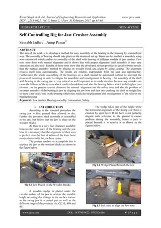
1. Kiran Singh et al. Int. Journal of Engineering Research and Application www.ijera.com
ISSN : 2248-9622, Vol. 7, Issue 2, ( Part -3) February 2017, pp.61-66
www.ijera.com DOI: 10.9790/9622- 0702036166 61 | P a g e
Self-Controlling Rig for Jaw Crusher Assembly
Saurabh Jadhav1
, Anup Pawar2
ABSTRACT
The aim of the work is to develop a method for easy assembly of the bearing in the housing by standardized
way. The assembly of bearing should take place on the atomized set up. Based on this method a assembly setup
was constructed which enables to assembly of the shaft with bearing of different models of jaw crusher. First
tests were done with manual alignment and it shows that with proper alignment shaft assembly is very easy
operation and also safe. Results of those tests show that the developed system provides as good or better results
than the manual assembly method by placing on wooden block and aligns by using jacking. The alignment
process itself runs automatically. The results are reliable, independent form the user and reproducible.
Furthermore the whole assembling of the bearings on a shaft should be automated without to interrupt the
process of mounting in order to fatigue for assembler and misalignment in bearing . the assembly of the shaft
with bearing in the swing jaw is very critical as well important so it needs attention because any mistake can
cause the failuare of the system which result in breakdown and also the bearing failure which is the highest cost
element . so the propose system eliminate the manual alignment and the safety issue and also the problem of
incorrect assembly of the bearing in jaw by aligning the jaw bore and then only pushing the shaft in straight line
so there is no shock load on the bearing which may result the misplacement and misalignment of thr roller in the
bearing housing
Keywords: Jaw crusher, Bearing assembly, Automation, Safety.
I. INTRODUCTION
According to the standard procedure the
swing jaw is first painted then allowed to dry.
Further the eccentric shaft assembly is assembled
in the jaw, but before that the jaw is place on the
wooden blocks.
As there is a very fine clearance available
between the outer race of the bearing and the jaw
bore it is necessary that the alignment of their axis
is perfect, also the line of action of the lever hoist
must coincide with the jaw bore centre.
The present method to accomplish this is
to place the jaw on the wooden blocks as shown in
the figure below.
Fig 1.1 Jaw Placed on the Wooden Blocks
A wooden wedge is placed under the
circular surface of the jaw to achieve the variable
height occurring due change in the surface texture
as the swing jaw is a casted part as well as the
different range of the products viz. CJ211, 409 and
411.
The wedge takes care of the height while
the horizontal alignment of the Swing Jaw Bore is
checked by spirit level. If the bore is not perfectly
aligned with reference to the ground it causes
problem during the assembly, hence a jack is
placed beneath it to resolve it as shown in the
figures below.
Fig 1.2 Wedge Placed beneath the Jaw
Fig 1.3 Jack used to align the Jaw bore
RESEARCH ARTICLE OPEN ACCESS
2. Kiran Singh et al. Int. Journal of Engineering Research and Application www.ijera.com
ISSN : 2248-9622, Vol. 7, Issue 2, ( Part -3) February 2017, pp.61-66
www.ijera.com DOI: 10.9790/9622- 0702036166 62 | P a g e
When all this as completed then the
further assembly procedure is carried out as
follows:
1. Lift the Shaft using Belt and align its centre
with the jaw bore centre.
2. Attach lever hoist chain to the eye bolt fitted in
the shaft.
3. Push the shaft inside the Jaw bore and pull it
from the other side by lever hoist
simultaneously.
4. While inserting the first bearing, make sure
that the outer race of bearing is perfectly
aligned with the jaw bore for easy fitment of
bearing in shaft. When it is done rest the shaft
on the wooden block.
Fig 1.4 Shaft Assembly with Jaw
Fig 1.5 Pull the Shaft through guide side by lever
hoist
Hence the preparations made before
actually assembling the shaft with jaw are tedious
and time consuming, but are essential non value
adding activities. They also induce more fatigue on
the production technologist working on the job.
II. LITRATURE SURVEY
Design and Development of Fixture for
eccentric shaft: A Review
This paper shows a fixture design system
of eccentric shaft for ginning machine. Fixture is
required in various industries according to their
needs. Designer design fixture according to
dimension parameterized by industry to get their
production tar gate. In old system manufacturing
process performing operation on eccentric shaft is
delicate. So gripping a work piece in required
position during a manufacturing operation fixture is
very necessary and vital. Because the shaft is
eccentric so for this need of manufacturing process
Designer design proper fixture for eccentric shaft.
Fixtures lowers operation time and up bring
productivity and apex quality of operation is
possible.
Fixture designers support expert system and
concurrent engineering
Researcher shows the main outlines of
their process, that fixture design support system is
developed on the basis of an expert system body.
Researcher gives idea of how the use of that kind
of tool is determinant factor for reactivity in the
fixture design protocols in concurrent engineering.
The paper aim for the development of fixture
designer’s support. Researcher present a outlining
of the design method and expression of the trade
norms in the expert system formalism. Researcher
has developed formulating industrial expertise
SEACMU (System Expert d'Aide il la Conception
des Montages d'Usinage for expert system for final
design). That is a fixture designers' support expert
system. SEACMU is based on a adapted part
modeling to the fixture design.
III. PROBLEM STATEMENT
The swing jaw of all the three models of
Jaw Crusher is assembled on three wooden blocks.
As there are three different size models it becomes
difficult to adjust the height of wooden blocks as
per the model. It is a time consuming process as the
swing jaw weighs 8.1 Tonne and requires
continuous help of overhead crane and extra
manpower.
Problem also arises because of the
material of the swing jaw, is casted and every
single piece of swing jaw has different irregular
outer surface which tends to improper resting on
the wooden blocks.
During assembly of shaft into the bore of
the swing jaw, due to improper resting of swing
jaw, another problem arises i.e. misalignment of
line of action and center bore.
When the shaft is pulled by lever hoist,
because of no constraint in direction of pull the
swing jaw tends to move along with the shaft in the
direction of force applied.
Safety is another major challenge in the
assembly process as the blocks are a type of
temporary support, constant threat to the
production technologist is there.
In order to minimize the problems
hydraulic jacks are also used for vertical height
adjustment and horizontal bore alignment and
overhead crane is in continuous use which
increases the material, manpower and time
requirement.
3. Kiran Singh et al. Int. Journal of Engineering Research and Application www.ijera.com
ISSN : 2248-9622, Vol. 7, Issue 2, ( Part -3) February 2017, pp.61-66
www.ijera.com DOI: 10.9790/9622- 0702036166 63 | P a g e
Use of conventional support like wooden
blocks, hydraulic lift and extensive use of overhead
crane makes the work procedure more tedious and
ergonomically it is not right procedure as it creates
fatigue and affects manpower’s health adversely.
IV. METHODOLOGY
This phase of the fixture-design process
requires the most creativity. A typical work piece
can be located and clamped several different ways.
The natural tendency is to think of one solution,
then develop and refine it while blocking out other,
perhaps better solutions.
The above problem can have solution as below
1. Wedge Operated Mechanically by using screw
and nut mechanism
2. Two hydraulic jacks used to lift the rear end of
the jaw to required height and degree
3. Two Screw Jacks used to lift the jaw.
From the above three the first option of
mechanical wedge can take care of height
adjustment of the jaw, but no the horizontal
alignment.
The hydraulic jack system cannot be used
as oil spills from the system will cause slippery
shop surfaces as well as raises the fire hazards as
during assembly process there may be need of
welding and gas cutting during rejection and
rework.
This leaves only the last option of having
two screw jacks in conjunction with level sensors
beneath the jaw bore two lift it such that require
height is achieved and the jaw bore gets perfectly
aligned.
4.1 Important Factors While Designing Fixture
Designing and fixtures depends upon so
many factors. These factors are analysed to get
design inputs for jigs and fixtures. The list of such
factors is mentioned below:
a. Study of Workpiece and finished component
size and geometry.
b. Type and capacity of the machine, its extent of
automation.
c. Provision of locating devices in the machine.
d. Available clamping arrangements in the
machine.
e. Available aligning devices, their accuracy.
f. Evaluation of variability in the performance
results of the machine.
g. Rigidity and of the machine under
consideration.
h. Required level of the accuracy in the work and
quality to be produced.
Fig 4.1 Setup of the Fixture
Fig 4.2 Setup while assembly
Analytical calculation:
Design Power
Screw
Material: Alloy steel ,
Dc = 23mm
Nominal diameter = 26mm
Major diameter = 26mm
Length of the screw = 100mm
Design of Nut
Nut diameter = 26.5
P= 2mm
Dm = =25mm
Worm & Worm gear design
OD of worm = Dow = 37
Dg = 78 mm
Throat diameter = 83.99
Face width =b = 30mm
Worm Gear
Speed = 1750
Velocity ratio = 26
No of start = 1
No of teeth = 26
Standard module = 3mm
Centre distance = 43.44 mm
Diameter of worm = 32.21
Face length = 70mm
Gear pair dimensions
Pinion
4. Kiran Singh et al. Int. Journal of Engineering Research and Application www.ijera.com
ISSN : 2248-9622, Vol. 7, Issue 2, ( Part -3) February 2017, pp.61-66
www.ijera.com DOI: 10.9790/9622- 0702036166 64 | P a g e
Module (m) = 5
No of Teeth = 12
P.C.D = 60
Face Width = 50
Shaft Size = 25
Key Size = 8X7X60
Gear
Module (m) = 5
No Of Teeth = 42
P.C.D = 210
Face Width = 50
Shaft Size = 35
Key Size = 10X8X60
Analysis on software:
V. ANALYSIS REAR END ASSEMBLY
FRAME
In any analysis software to give accurate
results it is necessary that the constraints and the
load application must be as per actual conditions
on the system. The analysis of the rear end frame is
as shown in the fig below
Fig 5.1 Load analysis
As the maximum stress induced is 107. 38Mpa on
the top plate which is less than allowable stress
hence the design is safe.
5.1 Jackleg Assembly
Fig 5.2 Buckling Load analysis
5.2 Screw
Fig 5.3 Buckling Load analysis
VI. WORKING MODEL
Gearbox Drawing
Fig 6.1 Gearbox Automated system
Fig 6.2 Gearbox details
5. Kiran Singh et al. Int. Journal of Engineering Research and Application www.ijera.com
ISSN : 2248-9622, Vol. 7, Issue 2, ( Part -3) February 2017, pp.61-66
www.ijera.com DOI: 10.9790/9622- 0702036166 65 | P a g e
1.0 Design Of Control System –
Fig 5.1 Block Diagram of electrical Circuit
6.1 Motor-
We have output power requirement of 100
W from prime mover to rotate the input worm at
desirable speed and rated torque. So to met this
requirement we decided to use 0.5 HP ( i.e. 373 W)
DC motor for this specific application.
Specification-
Volts-12 , Amps- 45
0.15 - 0.5 HP, 0.1 - 0.4 KW
Shaft Diameter: 0.625" - 15.9 mm
Face Mount in Any of the Direction
Operates in Both two Directions
All Ball Bearing Construction
Brush Life 3,000 Hrs Minimum
Ambient Temp 40 degrees C
Insulation Class
6.2 DPST Switch- (Double pole single throw)
Fig 6.2.1 DPST Switch
Each terminals of a double pole single
switch can ei be in the (closed) or in the off (open)
condition . A Double Pole Single Switch has a lot
of versatility or the variation being that it accepts 2
inputs, which makes it able to drive 2 different
outputs in a circuit. . It drives depends on the
circuit design and what the circuit is intended to do.
But DPST have enormous applications in circuits.
Reasons for using the DPST switch-
a. Manual operation of the motors in case of
failure of the sensors
b. To move the fixture up & down as per the
operators requirements
c. To control speed & direction of rotation of the
motor output shaft
VII. DESIGN OF MANUAL SYSTEM
7.1 Manual Gearbox
The Manual system consist only screw of
gear box arrangement without having motor as the
prime mover. This will make the system less
complicated and also reduce the cost of the motor.
Easier way is that to operate the screw
directly with the hand lever, but according to the
ergonomic study the max Grip force applied by an
average human being is 100N while we need the a
Torque of 250Nm approx. to lift the jaw.
As we know that
As it is not feasible to have such a long
lever there is need of reduction gearbox as well as
we have to transmit the torque at right angles to lift
the load vertically, hence, it is convenient to use the
worm and worm wheel drive.
The worm gears are widely used for
transmitting power at high velocity ratios between
non-intersecting shafts that are generally, but not
necessarily, at right angles. It can give velocity
ratios as high as 300:1 or more in a single step in a
minimum of space, but it has a lower efficiency.
As the worm and worm designed earlier in
the above gearbox is compatible with the manual
design it will have of 26, calculating the torque
applied on worm
Now the length of lever
Which means the technologist can use a
spanner of 100mm length to operate the screw. We
can develop a feature of bolt head on the worm
shaft so that it can also be operated using impact
wrench. As there are same axial loading conditions
the bearings and bearing covers selected are same
as that of automated gearbox. The detailed structure
of the gearbox designed is as shown in the figure
below
6. Kiran Singh et al. Int. Journal of Engineering Research and Application www.ijera.com
ISSN : 2248-9622, Vol. 7, Issue 2, ( Part -3) February 2017, pp.61-66
www.ijera.com DOI: 10.9790/9622- 0702036166 66 | P a g e
Fig 7.1 Gearbox for manual system
Fig 7.2 Gearbox details
VIII. CONCLUSION
A set up to aligning the bore and pulling
center line Developed. Based on assembly of the
bearings done Jaw crusher which enables the easy
assembly increased safety and also reduces the
chances of the premature bearing failure because of
pulling shock load. Results of these fixture
implementations are there will be lot of time saving
along with increased life of bearing as
misalignment in spherical roller bearing is not
there. Also earlier this is very critical operation so
skilled manpower and continue use of crane
required which is also eliminated the next stage of
the project is to calculate the pulling force of the
bearing in jaw according to required fit type and
pulling withy sensor which compare the force
required actual so there are no chances of the loose
and tight fit of bearing in jaw and if jaw bore size is
within limit then only the bearing assembly will be
done.
ACKNOWLEDGMENT
We take immense pleasure in thanking our
college management for having permitted us to
carry out this project work. Words are inadequate
in offering our thanks to our respected co-operation
in carrying out project work in the starting phase of
the project like requirement analysis and literature
survey. We also express our at most gratitude to
Dr. K. B. Kale Head of department of Computer
Engineering, for this valuable co-operation in
selecting the project topic and guiding us stepwise
ahead. Inspiration and guidance are invaluable in
every aspect of life, especially in field of education,
which we have received from our respected project
guide Dr. R. R. Navtar who has helped a lot In
first two phase of project like topic selection then
information gathering and guide us to throughout
the project work and gave earnest co-operation
whenever required. We would like to express
sincere gratitude towards him. At last, we would
like to take this opportunity to convey thanks to all
my staff members, who directly or indirectly
encouraged and helped us project work. Finally yet
importantly, we would like to express heartfelt
thanks to our beloved parents for their blessings,
our friends/classmates for their and helps and
wishes.
REFERENCES
[1]. Meridith Grimsley and Birmingham, Slide
assembly fixture for rear hub assembly,
United States patent, Patent No. 7225516,
(2007).
[2]. Frank M Prucha and Birmingham, Ring
assembly fixture, United States patent,
Patent No. 2865091, (1958).
[3]. William Hunter, Upland, Gerard A Naab
and Morton, Assembly and test fixture,
United States patent, Patent No. 160394,
(1964).
[4]. Shalette Farmer, Instrument panel
assembly fixture, United States patent,
Patent No. 2010/00450651A1, (2010).
[5]. John B. Gray 3 and William R. Yeich,
Assembly Fixture, United States patent,
Patent No. 2801329, (1957).
[6]. Arthur Richard Baker Jr., Fixture for
assembling electronic circuit modules,
United States patent, Patent No.5732462,
(1998).
10