Downloaded 506 times


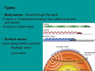


Seismic waves are energy propagated through the earth by earthquakes or artificial sources. There are two types of body waves (P and S waves) that travel through the earth and surface waves (Rayleigh and Love waves) that travel along the earth's surface. Seismic wave velocities depend on the elastic properties and density of the earth materials and are used to determine subsurface layering and structures. Analysis of travel times and slopes of seismic wave arrivals on record sections allows calculation of subsurface velocities and reflection/refraction of waves at interfaces between subsurface layers.


