Downloaded 188 times

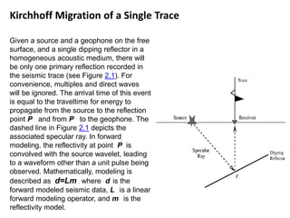
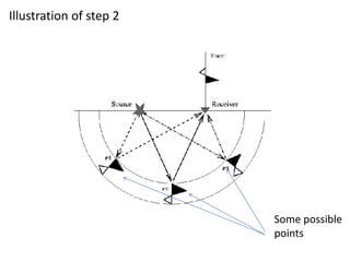
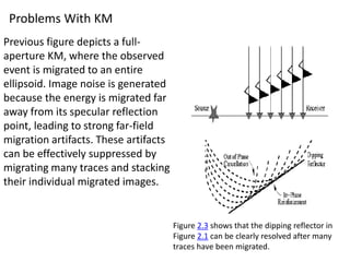
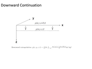


Kirchhoff migration is a widely used seismic data processing method. It works by back projecting observed seismic event energy from traces to possible subsurface reflection points based on traveltime. This smears the event energy to all possible subsurface locations, generating artifacts. Stacking multiple migrated traces helps resolve the true dipping reflector. Ray tracing is used to build the traveltime field. Kirchhoff migration is computationally expensive, taking days to process post-stack or months for pre-stack data. Representing the earth in 3D rather than 2D is preferable but requires knowing the 3D velocity model which is challenging.