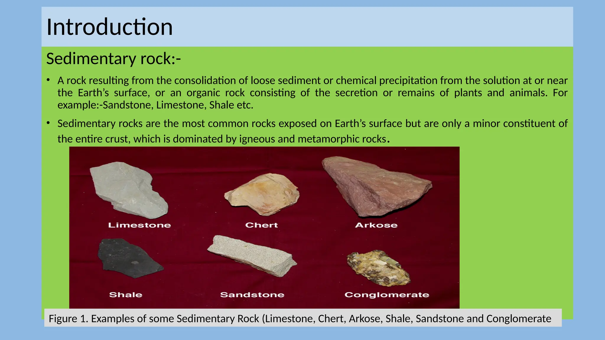
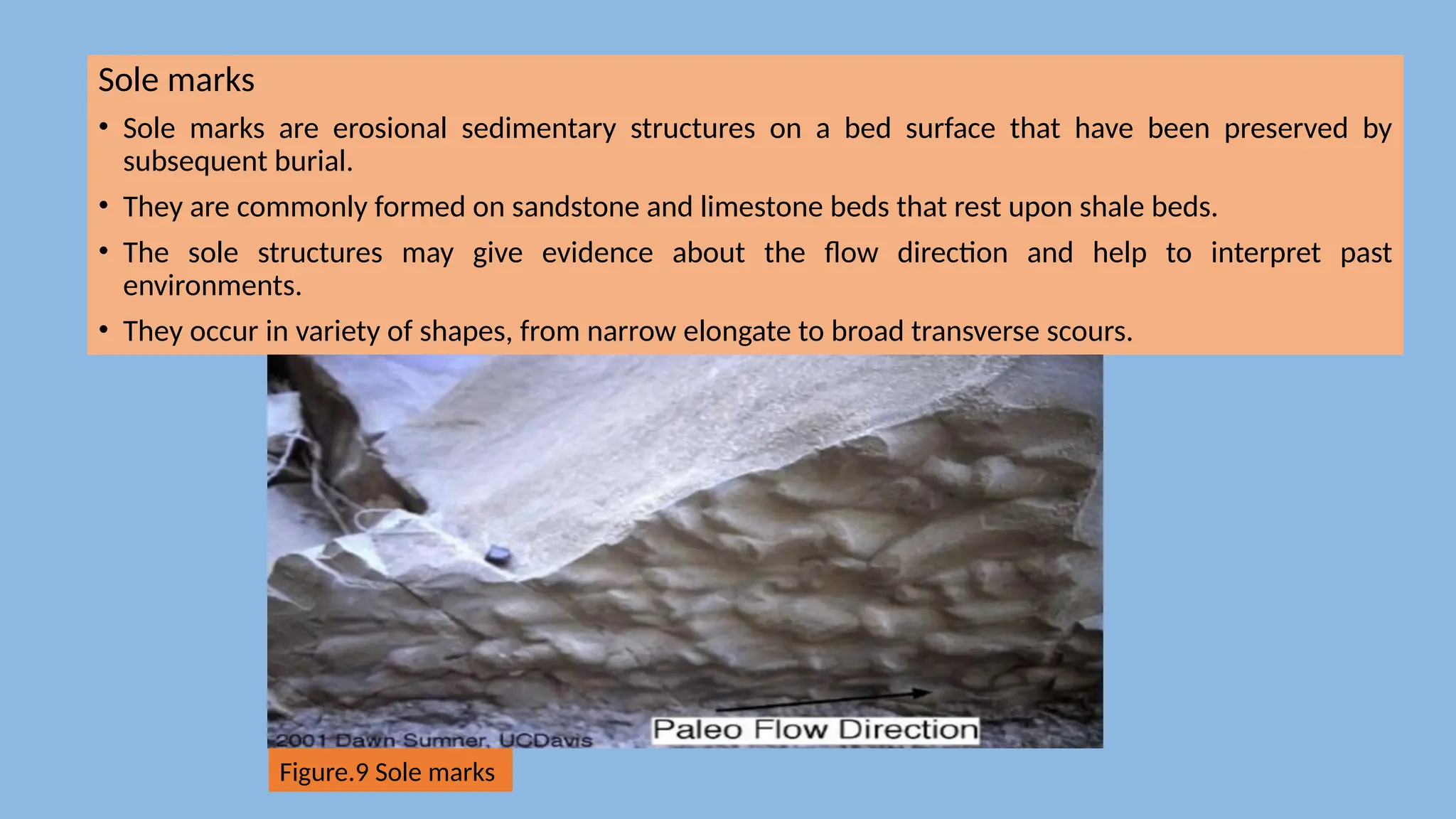
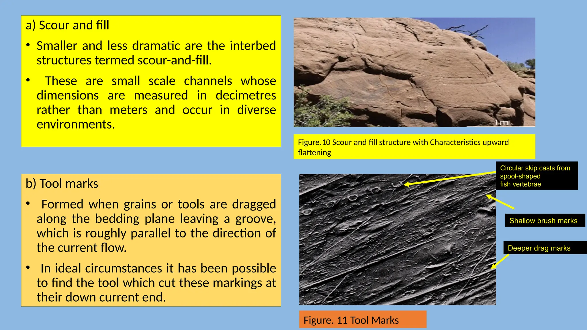
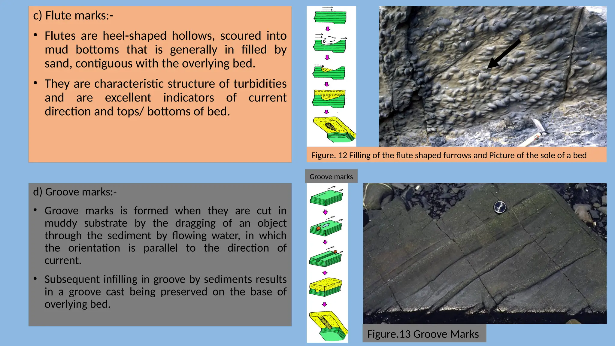
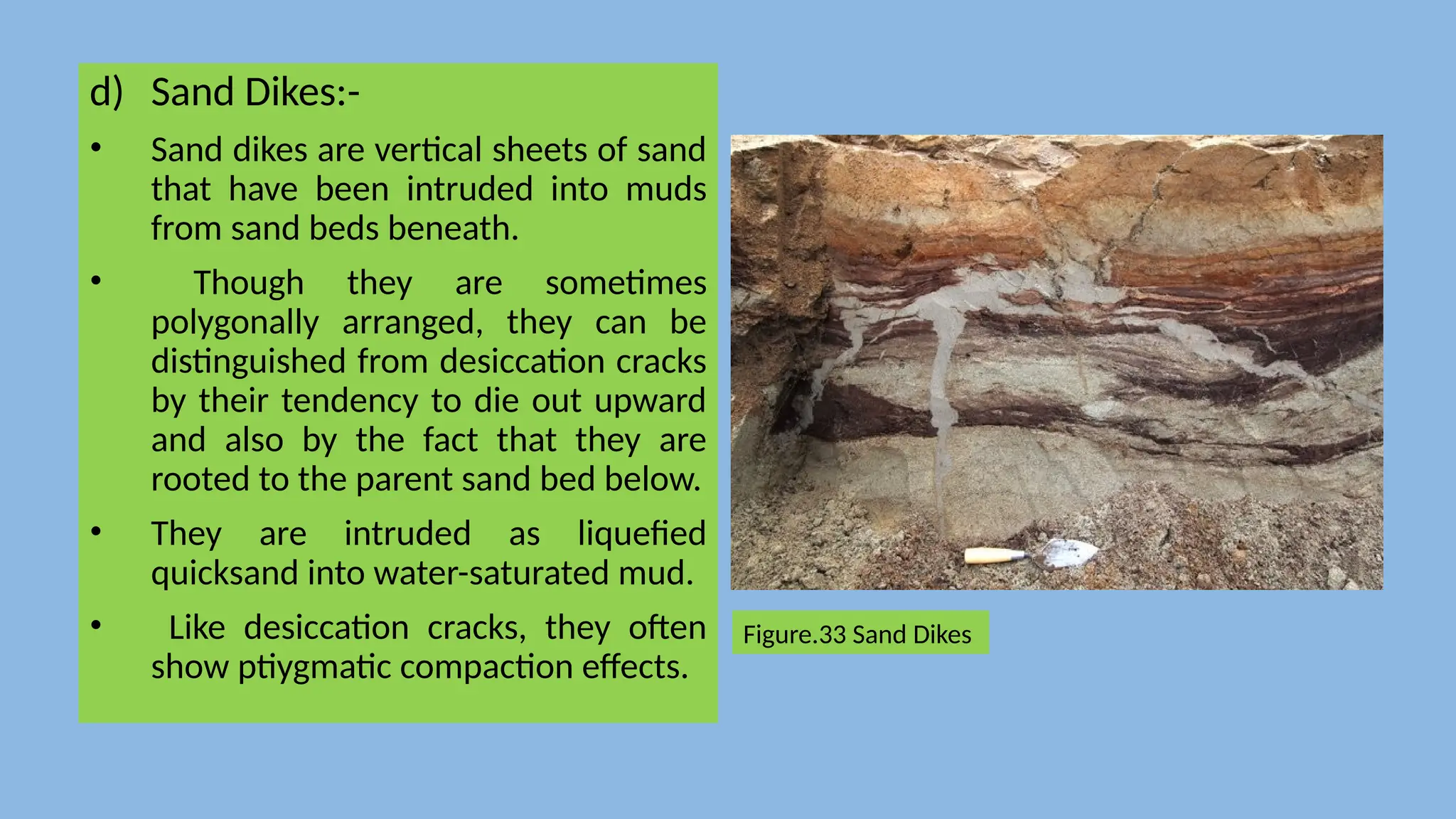
Presented By:
Name: Arun Shreshta
M.Sc. Geology
Central Department of Geology
Kritipur, Kathmandu
Sedimentary Structure and
Paleocurrent Analysis
Outlines for Sedimentary Structure
• Introduction
• Biogenic Sedimentary Structure
• Primary Inorganic Sedimentary Structure
1. Pre-depositional Sedimentary Structure
2. Syn-depositional Sedimentary Structure
3. Post-depositional Sedimentary Structure
4. Miscellaneous Sedimentary Structure
• Significance of Sedimentary Structure
• Paleocurrent Analysis
Introduction
Sedimentary rock:-
• A rock resulting from the consolidation of loose sediment or chemical precipitation from the solution at or near
the Earth’s surface, or an organic rock consisting of the secretion or remains of plants and animals. For
example:-Sandstone, Limestone, Shale etc.
• Sedimentary rocks are the most common rocks exposed on Earth’s surface but are only a minor constituent of
the entire crust, which is dominated by igneous and metamorphic rocks.
Figure 1. Examples of some Sedimentary Rock (Limestone, Chert, Arkose, Shale, Sandstone and Conglomerate
Sedimentary Structure
• Sedimentary structures are the larger, generally three-dimensional
physical features of sedimentary rocks; that are best seen in outcrop
or in large hand specimens rather than through a microscope.
• These structures are typically an indication of what the sedimentary
environment was like.
• include features like bedding, ripple marks, fossil tracks and trails,
mud cracks and so on.
Types of Sedimentary Structure
• Sedimentary structures are arbitrarily divided into primary and secondary
structures on the basis of their morphological or descriptive characteristics or
presumed mode of origin and which can be described as follows:-
1. Primary structure
• Pre-depositional structure
• Syn-depositional structure
• Post-depositional structure
• Miscellaneous structure
2. Secondary structure
• Chemical Sedimentary Structure
Biogenic Sedimentary Structure
• Biogenic sedimentary structures (trace fossils or ichnofossils) are biologically
produced structures that represent the activity of soft-bodied organisms that are
not generally preserved.
• Such organisms are commonly dominant component of biomass of many
environments.
• It includes, tracks, trails, burrows, borings, fecal pellets and other traces made by
the organisms.
• It is useful as facies indicators and also provide valuable clues to the
interpretation of paleodepositional environments.
Four broad categories of biogenic structures are recognized:
1. Bioturbation structures (burrows, tracks, trails, root penetration
structures) arising from organic activity that tends to penetrate,
mix, or otherwise disturb sediment,
2. Bio erosion structures (borings, scrapings, bitings),
3. Biostratification structures (stromatolites, graded bedding of
biogenic origin
4. Excrement (coprolites, such as fecal pellets or fecal castings).
Stromatolites:-
• Stromatolites are laminated structure
composed of particulate sand, silt, and clay
sized sediment, which has been formed by the
trapping and binding of detrital sedimentary
particles by an algal material and biochemical
precipitation of carbonate. Hence it is also
called algal stromatolite.
• Stromatolites are very common in Precambrian
carbonate successions but they also occur in
many Phanerozoic limestones, particularly
those of peritidal origin.
• It is most common in carbonate rocks, but have
been reported from siliciclastic rocks.
Figure.2 Four common stromatolitic structures: domal,
columnar and planar stromatolites, and oncolites.
Stromatolotes
Tracks and Trails:-
• Tracks or footprints are impressions on the surface of a bed of
sediment produced by the feet of animals. Examples include
dinosaur footprints or bird tracks.
• In some cases, tracks are found as sole marks on the bottoms
of beds, where sediment has infilled the tracks, and preserved
them as casts.
• Trails are groove-like impressions on the surface of a bed of
sediment produced by an organism which crawls or drags part
of its body. Trails may be straight or curved.
• These structures imprinted on the surface are categorized as
trace fossils, which are common in sandstones and shale, but
these have been reported from carbonate rocks also.
• Trace fossils can form under both subaerial and subaqueous
conditions. In subaerial environments, organisms such as
insects, spiders, worms, millipedes, snails, and lizards produce
various types of burrows and tunnels; vertebrate organisms
leave tracks; and plants leave root traces.
Tracks
Trails
Burrows and Boring:-
• Burrows are excavations made by animals into soft
sediment, that may be used by organisms for
dwellings, or may be produced as a subterranean
organism moves through the soil or sediment in
search of food.
Figure.3 Burrow structure in Triassic rocks
• It is commonly filled in by sediment of a different
color or texture than the surrounding sediment, and
in some cases, it may have an internally laminated
backfilling.
• Borings are holes made by animals into hard
material, such as wood, shells, rock, or hard sediment
and are usually circular in cross-section.
• It can be excellent top and bottom indicators and
help in the reconstruction of sedimentary
environment.
Figure. 4 cobble was tossed about in a coral reef
complex that was part of the ancient Fortuna Basin
(categories of boring).
Coral Reefs:-
• Reefs are dome to elongate, massive to bedded forms that are accumulated largely
as a result of organic buildups horizontally or nearly flat- lying strata.
• They are built during carbonate deposition by organisms that biogenetically
precipitate carbonate materials.
Figure.5 Florida Keys fossil reef corals, fossil corals from Puerto Rico, California fossil solitary corals, and fossil coral from Isla
Guadalupe, Baja California
Casts and Molds:-
• Organisms buried in sediment slowly
decay, leaving hollow space that contains
an exact imprint of the organisms shape
and size. Later, when this hollow space is
filled with materials, it takes the shape of
the mold, forming a cast.
Figure.6 Two Ammonites and their molds and casts
Escape structures:-
• Escape structures are columns, holes, or
tubes that cut across bedding and are in
filled with sediment after the escape of
water or a burrowing organism that had
been trapped beneath a newly deposited
sediment layer.
Figure.7 Water-escape structure developed in the liquefied
sandstone layers of the Yangjiaodong Section in Lingshan
Island.
Primary Structure
• Primary sedimentary structures originates during the formation of rocks either
through depositional process or deformation processes.
• It gives an ultimate goal to understand the total history of a deformed rock and
not just its deformational history.
• It also help to understand that the processes of deposition and deformation are
not necessarily isolated in time.
• It can be divided into various types on the basis of their morphology and time of
formation, which are shown in Table 1.
Table 1.
1.1 Pre- depositional Sedimentary Structure
• Pre-depositional sedimentary structures occur on surfaces between
beds.
• They were formed before the deposition of the overlying bed.
• The majority of this group of structures are erosional in origin.
Channel
• The largest pre-depositional interbed structures are channels that may be kilometers wide and hundreds of meters
deep.
• They occur in diverse environments ranging from subaerial alluvial plains to submarine continental margins.
• Channeling is initiated by localized linear erosion by fluid flow aided by corrosive bed load.
• Channels are of great economic importance for several reasons. As they can be petroleum reservoirs and aquifers,
can be found in placer and replacement mineral ore bodies, and can cut out coal seams.
Figure.8 Flood delta channels incising into barrier-island deposits: Kentucky, USA
Sole marks
• Sole marks are erosional sedimentary structures on a bed surface that have been preserved by
subsequent burial.
• They are commonly formed on sandstone and limestone beds that rest upon shale beds.
• The sole structures may give evidence about the flow direction and help to interpret past
environments.
• They occur in variety of shapes, from narrow elongate to broad transverse scours.
Figure.9 Sole marks
a) Scour and fill
• Smaller and less dramatic are the interbed
structures termed scour-and-fill.
• These are small scale channels whose
dimensions are measured in decimetres
rather than meters and occur in diverse
environments.
b) Tool marks
• Formed when grains or tools are dragged
along the bedding plane leaving a groove,
which is roughly parallel to the direction of
the current flow.
• In ideal circumstances it has been possible
to find the tool which cut these markings at
their down current end.
Figure.10 Scour and fill structure with Characteristics upward
flattening
Deeper drag marks
Shallow brush marks
Circular skip casts from
spool-shaped
fish vertebrae
Figure. 11 Tool Marks
c) Flute marks:-
• Flutes are heel-shaped hollows, scoured into
mud bottoms that is generally in filled by
sand, contiguous with the overlying bed.
• They are characteristic structure of turbidities
and are excellent indicators of current
direction and tops/ bottoms of bed.
d) Groove marks:-
• Groove marks is formed when they are cut in
muddy substrate by the dragging of an object
through the sediment by flowing water, in which
the orientation is parallel to the direction of
current.
• Subsequent infilling in groove by sediments results
in a groove cast being preserved on the base of
overlying bed.
Figure. 12 Filling of the flute shaped furrows and Picture of the sole of a bed
Groove marks
Figure.13 Groove Marks
1.2 Syn-depositional Sedimentary Structure
• Syn-depositional structures are those actually formed during sedimentation. They
are therefore, essentially constructional structures that are present within
sedimentary beds.
• Bedding, stratification, or layering is probably the most fundamental and diagnostic
feature of sedimentary rocks.
• Synsedimentary intra-bed structures are of five categories. The morphology and
origin of these are now described as follows:
a) Bedding and Lamination
b) Graded bedding
c) Cross-bedding
d) Ripples and Cross-lamination
a) Bedding and Lamination:-
• Bedding and lamination define stratification.
• Bedding is thicker than 1 cm whereas lamination is thinner than 1 cm. Bedding is
composed of beds; lamination is composed of laminae.
• Parallel (also called planar or horizontal) lamination is a common internal structure of
beds.
Table.2: Terminology of bed thickness
Thickness Terminology
>1m Very thick-bedded
30cm-1m Thick-bedded
10-30cm Medium-Bedded
30mm-10cm Thin-bedded
10-30mm Very thin-bedded
3-10mm Thickly-laminated
<3mm Thinly-laminated
b. Lamina set = Stacking of genetically
related laminae
a. Alternation of sand and mud Boundary =
Bedding plain,
Figure.14 (a) Bedding plane and (b) Lamination
I. Massive bedding:-
• Genuine depositional massive bedding
is often seen in fine-grained, low-
energy environment deposits, such as
some clay stones, marls, chalks, and
calcilutites.
• Reef rock (biolithite) also commonly
lacks bedding, while in sandstones it is
rare.
• It is most frequently seen in very well-
sorted sands, where sedimentary
structures cannot be delineated by
textural variations.
Figure.15 sedimentary beds from
Morro Solar near Lima, Peru. Thicker layers are most
likely sandstone, and thinner layers are shale. Layering
tilts down to the right. Image credit: Miguel Vera León,
II) Flat- bedding:-
• One of the simplest intrabed structures is flat- or horizontal bedding that is parallel to the major bedding surface
and generally deposited horizontally.
• Flat-bedding occurs in diverse sedimentary environments ranging from fluvial channels to beaches and delta fronts.
• It occurs in sand-grade sediment, both terrigenous and carbonate.
• This occurs under shooting flow or a transitional flow regime with a Froude number of approximately.
Figure.16 Intercalation flat-bedding variegated kaolinitic clay and sandstone in
section II,Abu Darag Quarry, Red Sea area.
b) Graded bedding:-
• A graded bed is one in which there is a vertical change in
grain size.
• Normal grading is marked by an upward decrease in grain
size (Figure).
• Reverse grading is where the bed coarsens upward.
• Graded bedding is produced as sediment settles out of
suspension, normally during the waning phase of a turbidity
flow.
• Though the lower part of a graded bed is normally massive,
the upper part may exhibit the Bouma sequence of
sedimentary structures.
Figure.17 Gradded Bedding
c) Cross- bedding:-
• Cross-bedding is one of the most common and most important of all sedimentary
structures.
• It is all-over in traction current deposits in diverse environments.
• It consists of inclined dipping bedding, bounded by sub horizontal surfaces.
• Basically, two main types of cross-bedding can be defined by the geometry of the
foreset and their bounding surfaces:
i. Planar or Tabular planar cross-bedding, and
ii. Trough cross-bedding
• Cross bedding is commonly found in arenaceous Sediments, oolitic limestone and
Some type of Clastic limestone.
Figure.18 Horizontal, erosional surfaces separate inclined layers in this cross-bedded sandstone
sequence produced by migrating sand dunes. Dry Fork of Coyote Gulch, Canyons of the Escalante,
Utah. Photo by G. Thomas (wikimedia.org).
I) Planer or Tabular planer cross- bedding:-
• In tabular planar cross-bedding, planar foreset are bounded above and below by sub parallel sub
horizontal set boundaries.(applied and pathsala)
II) Trough cross-bedding:-
• In trough cross-bedding, upward concave foreset lie within erosion scours which are elongated
parallel to current flow, closed up current and truncated down current by further troughs.
Figure.19 Diagram illustrating planar bedding, and trough and tabular cross-bedding. The heavier lines
represent major bedding planes and the lighter ones are the internal laminations.
d) Ripples and Cross- lamination:-
• Ripples are a wave-like bed form that occurs in
fine sands subjected to gentle traction currents
(Figure).
• Migrating ripples deposit cross-laminated
sediment.
• Individual exceed 2-3 cm in thickness, in contrast
to cross-bedding, which is normally >50 cm thick.
• If a ripple is pointing downward it is called
“Lunate” while, pointing outward is called
“Linguoid.
• The Characteristics features of ripples depending
upon current velocity, particle size , persistence
of current direction and whether the fluid is air
or water.
Figure. 20 Ripple Marks
Ripples and Cross- lamination Cont.…..
• In cross-section ripples are divisible into those with symmetric and those with asymmetric profiles.
I) Symmetrical ripples, also called oscillation or vortex ripples, are commonly produced in shallow
water by the orbital motion of waves.
• In plan view they are marked by sub parallel, but occasionally bifurcate.
II) Asymmetric ripples, by contrast to symmetric ones, show a clearly differentiated low angle stoss side
and steep-angle lee side.
• Internally they are cross-laminated, with the cross-lamina concordant with the lee face.
• They are produced by unidirectional traction currents as, for example, in a river channel.
a b
Figure.21 (a) Symmetric ripple structure, (b) Asymmetric Ripple Structure
Flaser, lenticular and wavy beddings
a) Flaser bedding:-
• Flaser bedding is where cross-laminated sand contains mud streaks, usually in the
ripple troughs.
• These are commonly forms in relatively high energy environments ( sand flats)
b) Lenticular bedding:-
• Lenticular bedding is where mud dominates and the cross-laminated sand occurs in
lenses.
• They are commonly forms in relatively low energy environments.
c) Wavy bedding:-
• Wavy bedding is where thin-ripple cross-laminated sandstones alternate with
Mudrock.
• They are commonly forms in environments that alternate frequently from higher to
lower energies (mixed flats).
Figure.22 (1) Scheme of classification of flaser, wavy, and lenticular bedding and (2) Flaser Bedding(A), Wavy Bedding (B)
Lenticular Bedding (C)
1
2
1.3 Post-depositional Sedimentary Structure
• The post- depositional sedimentary structures is a result of deformation because, they can only
form after a sediment has been laid down.
• They can be arranged into three main groups according to whether the sense of movement was
dominantly vertical or dominantly lateral, whether the sediment deformed plastically in an
unconsolidated state, or whether it was sufficiently consolidated to shear along slide planes
(Table 3).
Table.3. Classification of Post-depositional Deformational Sedimentary Structures
1.3.1 Vertical Plastic Deformational Structures
• Deformational structures that involve vertical plastic movement of sediment and
are of two main types.
• One group occurs within sand beds and may be loosely referred to as quicksand
structures.
• Structures of the second group develop at the interfaces of sand overlying mud
that develop variety of structures.
• The mud: sand interface is often deformed in various ways. Most typically
irregular-rounded balls of sand depend from the parent sand bed into the mud
beneath.
• These structures are variously termed load casts, ball and pillow structures, etc.
a) Load Structure: Load Cast Generation
• Sole marking generally preserved on the lower side of the sand layer overlying the
mud layer.
• It is often associated with turbidities with a thin layer of coarser sediment on the top.
• It can also be defined as a bulbous depression formed on the base of a bed of
sediment.
• It is developed by the differential sinking of the sediment, while still soft, into less
dense sediment below.
Figure.23 Load Structure: Load Cast
b) Dish Structure:-
• Dish structure consist of concave-up
laminae, generally a few centimeters
across, which may be separated by
structure less zones (the pillars).
• Dish structures and dish-and-pillar
structures are formed by the lateral and
upward passage of water through
sediment.
• It is a particular variant of intra sand
deformation which is seen where lamina or
bedding planes are intermittently disrupted
and upturned like the rim of a dish.
• It is a type of dewatering phenomenon that
is particularly characteristic of fluidized
sand beds.
Figure.24 Dish Structure
c) Ball and Pillow Structure:-
• A sedimentary structure occurring on
the base of some sandstones which
are interbedded with mudstones.
• It is characterized by globular
protrusions and isolated pillows of
sandstones found in the underlying
mudstones.
• These structures form by the
differential settling of the
unconsolidated sand into less dense
mud below.
Figure.25 Ball and pillow structure
d) Convolute bedding:-
• Convolute bedding forms when complex folding and crumpling of beds or
laminations occur.
• This type of deformation is found in fine silty sands, and is usually confined to one
rock layer.
• This deformation is caused from sand being deposited onto mud, which is less
dense.
Figure.26 convolute bedding due to the explosion of pore water from loosely packed sand
e) Recumbent foreset
• These structures are caused by the vertical passage of water through loosely packed
sand.
• This water may be due to a hydrostatic head of water, for example, as is seen on an
alluvial fan (e.g., Williams, 1970).
• Alternatively, the water may be derived from the sediment itself.
• Sand will not compact significantly at the surface, but its grains may be caused to fall
into a tighter packing that consequently result in a decrease in porosity.
Figure.27 Recumbent foreset deformation in fluvial sediment
f) Convolute Lamination
• Laminated fine sands and silts also show pen contemporaneous vertical
deformation structures termed convolute lamination.
• This is similar in geometry to convolute bedding, but occurs in finer grained
sediment on a much smaller scale; generally in beds only a decimeter or so high.
• This is especially characteristic of turbidities, involving deformation of both the
laminated and cross-laminated Bouma units.
Figure.28 convolute lamination
1.3.2 Horizontal Deformational Structures
a) Slumps and Slides:-
• Slump structures involve the
penecontemporaneous plastic deformation of sand
and mud.
• Slump folds, commonly show clear evidence of
extensive lateral movement in a consistent
direction.
• They are commonly associated with
penecontemporaneous faulting and with major low
angle zones of decollement termed "slide planes."
a
b
Figure29. (a) Slump structure at cliff end and (b)
slump structure
1.4 Miscellaneous Structure
• It include rain prints, salt pseudomorphs, and various vertical dike-like structures
of diverse morphology and origin.
• These include desiccation cracks, synaeresis cracks, sedimentary boudinage, and
sand dikes.
a) Rain Prints:-
• Rain prints occur within siltstones and clay
stones, and where such beds are overlain
by very fine sandstones.
• In plan view, they are circular or ovate due
to windblown rain.
• They are typically gregarious and closely
spaced.
• Raised ridges are present around each
print.
• Individual craters range from 2 to 10 mm in
diameter.
• Rain prints are good indicators of subaerial
exposure
Figure.30 (a) Rain spots on surface of
mudstone and (b) Rain Prints
a
b
b) Salt Pseudomorphs
• Salt pseudomorphs occur in similar
lithological situations to rain prints in
which they are typically found where clay
stones or siltstones are overlain by
siltstones or very fine sandstones.
• They are molds formed in soft mud by
cubic halite crystals and often show the
concave "hopper" habit.
• An influx of turbid nonsaline water
dissolves the salt crystals and buries the
mold beneath a new layer of sediment.
Figure. 31 Salt Pseudomorphs
c) Desiccation Cracks:-
• Desiccation cracks, also known as sun
cracks, are downward tapering cracks in
mud, which are infilled by sand.
• In plan view they are polygonal which are
generally about 0.5m across, in which
individual cracks are a centimetre or so
wide.
• Shrinkage cracks are often recorded in
muddy sediments and are of two types:-
i) Desiccation cracks form subaerially;
ii) Synaeresis cracks form subaqueously
Figure.32 Shrinkage cracks: (a) formed by
desiccation, (b) formed through Synaeresis
d) Sand Dikes:-
• Sand dikes are vertical sheets of sand
that have been intruded into muds
from sand beds beneath.
• Though they are sometimes
polygonally arranged, they can be
distinguished from desiccation cracks
by their tendency to die out upward
and also by the fact that they are
rooted to the parent sand bed below.
• They are intruded as liquefied
quicksand into water-saturated mud.
• Like desiccation cracks, they often
show ptiygmatic compaction effects.
Figure.33 Sand Dikes
Significance of Sedimentary Structure
• Sedimentary structure remain a foundation for interpreting most ancient
• depositional environments.
• It is also used to interpret paleocurrent analysis.
• An understanding of erosional, depositional, and post-depositional
structures in a
• sediment can lead to sound paleoenvironment reconstructions.
• It is used to identify adequate aquifers for groundwater.
• It provide invaluable clues about the physiochemical conditions during and
• shortly after sedimentation.
Paleocurrent Analysis
• Paleocurrent analysis is the determination of ancient flow direction.
• Paleocurrent indicator are oriented sedimentary structure interpreted to have been deposited by ancient flows.
• Paleocurrent have the following implications :
 The direction of initial dip or paleoslope
 Provides direct information about orientation of the sedimentary structure
 The relation between facies boundaries and paleocurrent direction
 Establishing the relation between initial directional structure and the geometry of a lithologic unit such as a sandy
body or a bio herm
 Direction of sediment supply and such local problem as
 Evaluating the effect on reservoir performance inhomogeneities of primary origin that are linked to current direction
 Specifying the primary depositional fabric that controls the anisotropy of many geophysical properties
There are two main types of Paleocurrent indicators:
1. Unidirectional, which give a clear, single direction of flow
• Cross-bedding: The axis of a trough cross bed or the down-dip direction of a
tabular cross bed point the direction of paleo flow.
• Current Ripple Marks: The steeper side(Lee-side) indicate downstream direction
• Sole Marking/ flute casts: The short, steep side will point up stream, and the
long, tapered side points down stream.
• Clast Imbrication : Clasts line up in the direction of flow
2. Bidirectional, which give a good linear direction, but it is unclear which
direction along the linear trend the water flowed.
• Symmetrical Ripple Marks: flow is perpendicular to the ridge crest.
• Tool Mark: flow is along the mark
• Parting Lineation: flow is along the grains.
Measurement of Palecocurrent data
• The measurement of the orientation of sedimentary structures must be done with care.
• Ideally some kind of areal sampling grid should be used for regional paleocurrent mapping.
• Each sample station will generally consist of a cliff, quarry, stream section, road cut, etc. If it is to be
worth anything, paleocurrent analysis must be integrated with a full sedimentological study.
• it is necessary to record structural dip and strike. If it is excessive (greater than about 10) each
measurement must be tilt corrected on a stereographic net. both the azimuth and dip of planar
structures that need correction.
• For linear and planar structures in outcrops of low tectonic dip only the azimuth need be recorded.
• Fore set dip directions from cross-bedding should always be measured in plan view. Dip directions
seen in vertical sections should only be recorded as a last resort.
• As a rule of thumb in unipolar cross-bed systems, as in alluvium,25 readings are generally sufficient
to determine a vector mean with an accuracy of ±30.
• Many more readings may be needed, however, to establish well-defined modes in a section of
interbedded facies with different and often polymodal vectors.
Structure of Paleocurrent Measurement
Imbrication and clast orientation
• Ellipsoidal clasts frequently show a preferred alignment, in coarse-grained rocks.
• Alignment is visible in both plan view and in vertical section
• Several factors appear to control the range of inclination including clast size, clast sphericity, degree of clast contact and
paleohydraulic conditions.
• The longest a-axis(where a>b>c) tends to either normal to or parallel to the flow direction (Figure
• In sedimentary rock the best measure of paleocurrent direction is to obtained the mean vector of ab-plane
Figure.34 Pebble orientation and imbrication.(a) long axes parallel to flow, and (b) long axes tranverse to flow , arrow indicates the current flow
direction.
Cross bed dip azimuth
• Trough cross bedding is the good choice for measuring dip azimuth to reconstruct
palaeo flow direction. Forset beds are good indicators.
• Selection of 3-dimensional exposure to measure of dip azimuth and plunge in
vertical plane parallel to the dip azimuth is measured.
• The regional bedding plane is measured for tilt correction.
• All the planer data are plotted in the stereographic net a s the poles, and
restoration of the regional bedding and cross bedding applied.
Flute cast and other structure
• Dip azimuth and plunges in vertical plane can be measured for several flute casts
exposed.
• Flute casts have buldges that flatten away toward the flow direction.
Tilt correction of data
• Stereonet and equal-area net
• Procedure for plotting point
and plains
• Plotting poles of planes
• Tilt correction of linear
structure
• Tilt correction of Cross-
bedding
Figure. 35 (a) plot of bed ,pitch of linear structure, and rotation of bed and a line ;(b) plotting of a regional and a
cross bed, their poles, and rotation of their poles and restoration of the cross bed trend and plunge from the
restored pole structure.
Presentation of Paleocurrent Data
• Current Rose diagram is a tool to represent directional data
• The class interval with the greatest observation is the modal class
• The directional structure in rose diagram indicates the direction towards which current move (Figure )
• Most distribution produces a single mode (unimodal). Some have the two modes (bimodal) or more
(Polymodal)
• Data on the lines of movement which give sense of movement but not direction, will be plotted as two
opposite mode or azimuth values.
Figure.36 (a) Arose diagram showing flow direction from cross-bed azimuths, (b) A modal rose diagram showing line of movements of current lineation
on upper planer bedding, and (c) A composite rose diagram showing plots of line data (groove cast) and a direction data from casts.
Presentation of Results & Calculation Of Vector Means
• Dominant paleocurrent direction will usually be obvious from a rose diagram, for
accurate work it is necessary to calculate the mean Palaeocurrent direction i.e.
Vector mean.
• The vector means and dispersion can only be calculated for unimodal
palaeocurrent pattern(Figure.)
• Mathematically, Vector mean can be calculated using the following relationships:
• Vector mean, = X = arctan P
Where, P=
• Magnitude of resultant vector or
R =
• Vector magnitude(%)=L=
where, n = Number of reading and
Test of Significance
• The values S (vector magnitude) and n (number of
observation) can be used for the test of significance.
• Vector mean is the expression of preferred orientation
whilst the vector magnitude is a sensitive measure of
depression.
• It is necessary to test whether a set of paleocurrent
data possesses a distribution orientation which is
significantly different from random.
• It is important to notice that in a 360⁰ distribution any
value of the tangent will have two possible azimuths
that differ by 180⁰.
• Analysis of the palaeocurrent pattern needs to be combined with the study of the lithofacies for
maximum information. This features of the palaeocurrent pattern of the principal depositional
environments- fluvial, deltaic, Aeolian sands, shoreline-shallow shelf and turbidite basins as shown in
Table.
Table.3 Palaeocurrent patterns of principal depositional environments, together with best and other directional
structure
Sedimentary structure and Paleocurrent Analysis

Sedimentary structure and Paleocurrent Analysis

  • 1.
    Presented By: Name: ArunShreshta M.Sc. Geology Central Department of Geology Kritipur, Kathmandu Sedimentary Structure and Paleocurrent Analysis
  • 2.
    Outlines for SedimentaryStructure • Introduction • Biogenic Sedimentary Structure • Primary Inorganic Sedimentary Structure 1. Pre-depositional Sedimentary Structure 2. Syn-depositional Sedimentary Structure 3. Post-depositional Sedimentary Structure 4. Miscellaneous Sedimentary Structure • Significance of Sedimentary Structure • Paleocurrent Analysis
  • 3.
    Introduction Sedimentary rock:- • Arock resulting from the consolidation of loose sediment or chemical precipitation from the solution at or near the Earth’s surface, or an organic rock consisting of the secretion or remains of plants and animals. For example:-Sandstone, Limestone, Shale etc. • Sedimentary rocks are the most common rocks exposed on Earth’s surface but are only a minor constituent of the entire crust, which is dominated by igneous and metamorphic rocks. Figure 1. Examples of some Sedimentary Rock (Limestone, Chert, Arkose, Shale, Sandstone and Conglomerate
  • 4.
    Sedimentary Structure • Sedimentarystructures are the larger, generally three-dimensional physical features of sedimentary rocks; that are best seen in outcrop or in large hand specimens rather than through a microscope. • These structures are typically an indication of what the sedimentary environment was like. • include features like bedding, ripple marks, fossil tracks and trails, mud cracks and so on.
  • 5.
    Types of SedimentaryStructure • Sedimentary structures are arbitrarily divided into primary and secondary structures on the basis of their morphological or descriptive characteristics or presumed mode of origin and which can be described as follows:- 1. Primary structure • Pre-depositional structure • Syn-depositional structure • Post-depositional structure • Miscellaneous structure 2. Secondary structure • Chemical Sedimentary Structure
  • 6.
    Biogenic Sedimentary Structure •Biogenic sedimentary structures (trace fossils or ichnofossils) are biologically produced structures that represent the activity of soft-bodied organisms that are not generally preserved. • Such organisms are commonly dominant component of biomass of many environments. • It includes, tracks, trails, burrows, borings, fecal pellets and other traces made by the organisms. • It is useful as facies indicators and also provide valuable clues to the interpretation of paleodepositional environments.
  • 7.
    Four broad categoriesof biogenic structures are recognized: 1. Bioturbation structures (burrows, tracks, trails, root penetration structures) arising from organic activity that tends to penetrate, mix, or otherwise disturb sediment, 2. Bio erosion structures (borings, scrapings, bitings), 3. Biostratification structures (stromatolites, graded bedding of biogenic origin 4. Excrement (coprolites, such as fecal pellets or fecal castings).
  • 8.
    Stromatolites:- • Stromatolites arelaminated structure composed of particulate sand, silt, and clay sized sediment, which has been formed by the trapping and binding of detrital sedimentary particles by an algal material and biochemical precipitation of carbonate. Hence it is also called algal stromatolite. • Stromatolites are very common in Precambrian carbonate successions but they also occur in many Phanerozoic limestones, particularly those of peritidal origin. • It is most common in carbonate rocks, but have been reported from siliciclastic rocks. Figure.2 Four common stromatolitic structures: domal, columnar and planar stromatolites, and oncolites. Stromatolotes
  • 9.
    Tracks and Trails:- •Tracks or footprints are impressions on the surface of a bed of sediment produced by the feet of animals. Examples include dinosaur footprints or bird tracks. • In some cases, tracks are found as sole marks on the bottoms of beds, where sediment has infilled the tracks, and preserved them as casts. • Trails are groove-like impressions on the surface of a bed of sediment produced by an organism which crawls or drags part of its body. Trails may be straight or curved. • These structures imprinted on the surface are categorized as trace fossils, which are common in sandstones and shale, but these have been reported from carbonate rocks also. • Trace fossils can form under both subaerial and subaqueous conditions. In subaerial environments, organisms such as insects, spiders, worms, millipedes, snails, and lizards produce various types of burrows and tunnels; vertebrate organisms leave tracks; and plants leave root traces. Tracks Trails
  • 10.
    Burrows and Boring:- •Burrows are excavations made by animals into soft sediment, that may be used by organisms for dwellings, or may be produced as a subterranean organism moves through the soil or sediment in search of food. Figure.3 Burrow structure in Triassic rocks • It is commonly filled in by sediment of a different color or texture than the surrounding sediment, and in some cases, it may have an internally laminated backfilling. • Borings are holes made by animals into hard material, such as wood, shells, rock, or hard sediment and are usually circular in cross-section. • It can be excellent top and bottom indicators and help in the reconstruction of sedimentary environment. Figure. 4 cobble was tossed about in a coral reef complex that was part of the ancient Fortuna Basin (categories of boring).
  • 11.
    Coral Reefs:- • Reefsare dome to elongate, massive to bedded forms that are accumulated largely as a result of organic buildups horizontally or nearly flat- lying strata. • They are built during carbonate deposition by organisms that biogenetically precipitate carbonate materials. Figure.5 Florida Keys fossil reef corals, fossil corals from Puerto Rico, California fossil solitary corals, and fossil coral from Isla Guadalupe, Baja California
  • 12.
    Casts and Molds:- •Organisms buried in sediment slowly decay, leaving hollow space that contains an exact imprint of the organisms shape and size. Later, when this hollow space is filled with materials, it takes the shape of the mold, forming a cast. Figure.6 Two Ammonites and their molds and casts Escape structures:- • Escape structures are columns, holes, or tubes that cut across bedding and are in filled with sediment after the escape of water or a burrowing organism that had been trapped beneath a newly deposited sediment layer. Figure.7 Water-escape structure developed in the liquefied sandstone layers of the Yangjiaodong Section in Lingshan Island.
  • 13.
    Primary Structure • Primarysedimentary structures originates during the formation of rocks either through depositional process or deformation processes. • It gives an ultimate goal to understand the total history of a deformed rock and not just its deformational history. • It also help to understand that the processes of deposition and deformation are not necessarily isolated in time. • It can be divided into various types on the basis of their morphology and time of formation, which are shown in Table 1.
  • 14.
  • 15.
    1.1 Pre- depositionalSedimentary Structure • Pre-depositional sedimentary structures occur on surfaces between beds. • They were formed before the deposition of the overlying bed. • The majority of this group of structures are erosional in origin.
  • 16.
    Channel • The largestpre-depositional interbed structures are channels that may be kilometers wide and hundreds of meters deep. • They occur in diverse environments ranging from subaerial alluvial plains to submarine continental margins. • Channeling is initiated by localized linear erosion by fluid flow aided by corrosive bed load. • Channels are of great economic importance for several reasons. As they can be petroleum reservoirs and aquifers, can be found in placer and replacement mineral ore bodies, and can cut out coal seams. Figure.8 Flood delta channels incising into barrier-island deposits: Kentucky, USA
  • 17.
    Sole marks • Solemarks are erosional sedimentary structures on a bed surface that have been preserved by subsequent burial. • They are commonly formed on sandstone and limestone beds that rest upon shale beds. • The sole structures may give evidence about the flow direction and help to interpret past environments. • They occur in variety of shapes, from narrow elongate to broad transverse scours. Figure.9 Sole marks
  • 18.
    a) Scour andfill • Smaller and less dramatic are the interbed structures termed scour-and-fill. • These are small scale channels whose dimensions are measured in decimetres rather than meters and occur in diverse environments. b) Tool marks • Formed when grains or tools are dragged along the bedding plane leaving a groove, which is roughly parallel to the direction of the current flow. • In ideal circumstances it has been possible to find the tool which cut these markings at their down current end. Figure.10 Scour and fill structure with Characteristics upward flattening Deeper drag marks Shallow brush marks Circular skip casts from spool-shaped fish vertebrae Figure. 11 Tool Marks
  • 19.
    c) Flute marks:- •Flutes are heel-shaped hollows, scoured into mud bottoms that is generally in filled by sand, contiguous with the overlying bed. • They are characteristic structure of turbidities and are excellent indicators of current direction and tops/ bottoms of bed. d) Groove marks:- • Groove marks is formed when they are cut in muddy substrate by the dragging of an object through the sediment by flowing water, in which the orientation is parallel to the direction of current. • Subsequent infilling in groove by sediments results in a groove cast being preserved on the base of overlying bed. Figure. 12 Filling of the flute shaped furrows and Picture of the sole of a bed Groove marks Figure.13 Groove Marks
  • 20.
    1.2 Syn-depositional SedimentaryStructure • Syn-depositional structures are those actually formed during sedimentation. They are therefore, essentially constructional structures that are present within sedimentary beds. • Bedding, stratification, or layering is probably the most fundamental and diagnostic feature of sedimentary rocks. • Synsedimentary intra-bed structures are of five categories. The morphology and origin of these are now described as follows: a) Bedding and Lamination b) Graded bedding c) Cross-bedding d) Ripples and Cross-lamination
  • 21.
    a) Bedding andLamination:- • Bedding and lamination define stratification. • Bedding is thicker than 1 cm whereas lamination is thinner than 1 cm. Bedding is composed of beds; lamination is composed of laminae. • Parallel (also called planar or horizontal) lamination is a common internal structure of beds. Table.2: Terminology of bed thickness Thickness Terminology >1m Very thick-bedded 30cm-1m Thick-bedded 10-30cm Medium-Bedded 30mm-10cm Thin-bedded 10-30mm Very thin-bedded 3-10mm Thickly-laminated <3mm Thinly-laminated b. Lamina set = Stacking of genetically related laminae a. Alternation of sand and mud Boundary = Bedding plain, Figure.14 (a) Bedding plane and (b) Lamination
  • 22.
    I. Massive bedding:- •Genuine depositional massive bedding is often seen in fine-grained, low- energy environment deposits, such as some clay stones, marls, chalks, and calcilutites. • Reef rock (biolithite) also commonly lacks bedding, while in sandstones it is rare. • It is most frequently seen in very well- sorted sands, where sedimentary structures cannot be delineated by textural variations. Figure.15 sedimentary beds from Morro Solar near Lima, Peru. Thicker layers are most likely sandstone, and thinner layers are shale. Layering tilts down to the right. Image credit: Miguel Vera León,
  • 23.
    II) Flat- bedding:- •One of the simplest intrabed structures is flat- or horizontal bedding that is parallel to the major bedding surface and generally deposited horizontally. • Flat-bedding occurs in diverse sedimentary environments ranging from fluvial channels to beaches and delta fronts. • It occurs in sand-grade sediment, both terrigenous and carbonate. • This occurs under shooting flow or a transitional flow regime with a Froude number of approximately. Figure.16 Intercalation flat-bedding variegated kaolinitic clay and sandstone in section II,Abu Darag Quarry, Red Sea area.
  • 24.
    b) Graded bedding:- •A graded bed is one in which there is a vertical change in grain size. • Normal grading is marked by an upward decrease in grain size (Figure). • Reverse grading is where the bed coarsens upward. • Graded bedding is produced as sediment settles out of suspension, normally during the waning phase of a turbidity flow. • Though the lower part of a graded bed is normally massive, the upper part may exhibit the Bouma sequence of sedimentary structures. Figure.17 Gradded Bedding
  • 25.
    c) Cross- bedding:- •Cross-bedding is one of the most common and most important of all sedimentary structures. • It is all-over in traction current deposits in diverse environments. • It consists of inclined dipping bedding, bounded by sub horizontal surfaces. • Basically, two main types of cross-bedding can be defined by the geometry of the foreset and their bounding surfaces: i. Planar or Tabular planar cross-bedding, and ii. Trough cross-bedding • Cross bedding is commonly found in arenaceous Sediments, oolitic limestone and Some type of Clastic limestone.
  • 26.
    Figure.18 Horizontal, erosionalsurfaces separate inclined layers in this cross-bedded sandstone sequence produced by migrating sand dunes. Dry Fork of Coyote Gulch, Canyons of the Escalante, Utah. Photo by G. Thomas (wikimedia.org).
  • 27.
    I) Planer orTabular planer cross- bedding:- • In tabular planar cross-bedding, planar foreset are bounded above and below by sub parallel sub horizontal set boundaries.(applied and pathsala) II) Trough cross-bedding:- • In trough cross-bedding, upward concave foreset lie within erosion scours which are elongated parallel to current flow, closed up current and truncated down current by further troughs. Figure.19 Diagram illustrating planar bedding, and trough and tabular cross-bedding. The heavier lines represent major bedding planes and the lighter ones are the internal laminations.
  • 28.
    d) Ripples andCross- lamination:- • Ripples are a wave-like bed form that occurs in fine sands subjected to gentle traction currents (Figure). • Migrating ripples deposit cross-laminated sediment. • Individual exceed 2-3 cm in thickness, in contrast to cross-bedding, which is normally >50 cm thick. • If a ripple is pointing downward it is called “Lunate” while, pointing outward is called “Linguoid. • The Characteristics features of ripples depending upon current velocity, particle size , persistence of current direction and whether the fluid is air or water. Figure. 20 Ripple Marks
  • 29.
    Ripples and Cross-lamination Cont.….. • In cross-section ripples are divisible into those with symmetric and those with asymmetric profiles. I) Symmetrical ripples, also called oscillation or vortex ripples, are commonly produced in shallow water by the orbital motion of waves. • In plan view they are marked by sub parallel, but occasionally bifurcate. II) Asymmetric ripples, by contrast to symmetric ones, show a clearly differentiated low angle stoss side and steep-angle lee side. • Internally they are cross-laminated, with the cross-lamina concordant with the lee face. • They are produced by unidirectional traction currents as, for example, in a river channel. a b Figure.21 (a) Symmetric ripple structure, (b) Asymmetric Ripple Structure
  • 30.
    Flaser, lenticular andwavy beddings a) Flaser bedding:- • Flaser bedding is where cross-laminated sand contains mud streaks, usually in the ripple troughs. • These are commonly forms in relatively high energy environments ( sand flats) b) Lenticular bedding:- • Lenticular bedding is where mud dominates and the cross-laminated sand occurs in lenses. • They are commonly forms in relatively low energy environments. c) Wavy bedding:- • Wavy bedding is where thin-ripple cross-laminated sandstones alternate with Mudrock. • They are commonly forms in environments that alternate frequently from higher to lower energies (mixed flats).
  • 31.
    Figure.22 (1) Schemeof classification of flaser, wavy, and lenticular bedding and (2) Flaser Bedding(A), Wavy Bedding (B) Lenticular Bedding (C) 1 2
  • 32.
    1.3 Post-depositional SedimentaryStructure • The post- depositional sedimentary structures is a result of deformation because, they can only form after a sediment has been laid down. • They can be arranged into three main groups according to whether the sense of movement was dominantly vertical or dominantly lateral, whether the sediment deformed plastically in an unconsolidated state, or whether it was sufficiently consolidated to shear along slide planes (Table 3). Table.3. Classification of Post-depositional Deformational Sedimentary Structures
  • 33.
    1.3.1 Vertical PlasticDeformational Structures • Deformational structures that involve vertical plastic movement of sediment and are of two main types. • One group occurs within sand beds and may be loosely referred to as quicksand structures. • Structures of the second group develop at the interfaces of sand overlying mud that develop variety of structures. • The mud: sand interface is often deformed in various ways. Most typically irregular-rounded balls of sand depend from the parent sand bed into the mud beneath. • These structures are variously termed load casts, ball and pillow structures, etc.
  • 34.
    a) Load Structure:Load Cast Generation • Sole marking generally preserved on the lower side of the sand layer overlying the mud layer. • It is often associated with turbidities with a thin layer of coarser sediment on the top. • It can also be defined as a bulbous depression formed on the base of a bed of sediment. • It is developed by the differential sinking of the sediment, while still soft, into less dense sediment below. Figure.23 Load Structure: Load Cast
  • 35.
    b) Dish Structure:- •Dish structure consist of concave-up laminae, generally a few centimeters across, which may be separated by structure less zones (the pillars). • Dish structures and dish-and-pillar structures are formed by the lateral and upward passage of water through sediment. • It is a particular variant of intra sand deformation which is seen where lamina or bedding planes are intermittently disrupted and upturned like the rim of a dish. • It is a type of dewatering phenomenon that is particularly characteristic of fluidized sand beds. Figure.24 Dish Structure
  • 36.
    c) Ball andPillow Structure:- • A sedimentary structure occurring on the base of some sandstones which are interbedded with mudstones. • It is characterized by globular protrusions and isolated pillows of sandstones found in the underlying mudstones. • These structures form by the differential settling of the unconsolidated sand into less dense mud below. Figure.25 Ball and pillow structure
  • 37.
    d) Convolute bedding:- •Convolute bedding forms when complex folding and crumpling of beds or laminations occur. • This type of deformation is found in fine silty sands, and is usually confined to one rock layer. • This deformation is caused from sand being deposited onto mud, which is less dense. Figure.26 convolute bedding due to the explosion of pore water from loosely packed sand
  • 38.
    e) Recumbent foreset •These structures are caused by the vertical passage of water through loosely packed sand. • This water may be due to a hydrostatic head of water, for example, as is seen on an alluvial fan (e.g., Williams, 1970). • Alternatively, the water may be derived from the sediment itself. • Sand will not compact significantly at the surface, but its grains may be caused to fall into a tighter packing that consequently result in a decrease in porosity. Figure.27 Recumbent foreset deformation in fluvial sediment
  • 39.
    f) Convolute Lamination •Laminated fine sands and silts also show pen contemporaneous vertical deformation structures termed convolute lamination. • This is similar in geometry to convolute bedding, but occurs in finer grained sediment on a much smaller scale; generally in beds only a decimeter or so high. • This is especially characteristic of turbidities, involving deformation of both the laminated and cross-laminated Bouma units. Figure.28 convolute lamination
  • 40.
    1.3.2 Horizontal DeformationalStructures a) Slumps and Slides:- • Slump structures involve the penecontemporaneous plastic deformation of sand and mud. • Slump folds, commonly show clear evidence of extensive lateral movement in a consistent direction. • They are commonly associated with penecontemporaneous faulting and with major low angle zones of decollement termed "slide planes." a b Figure29. (a) Slump structure at cliff end and (b) slump structure
  • 41.
    1.4 Miscellaneous Structure •It include rain prints, salt pseudomorphs, and various vertical dike-like structures of diverse morphology and origin. • These include desiccation cracks, synaeresis cracks, sedimentary boudinage, and sand dikes.
  • 42.
    a) Rain Prints:- •Rain prints occur within siltstones and clay stones, and where such beds are overlain by very fine sandstones. • In plan view, they are circular or ovate due to windblown rain. • They are typically gregarious and closely spaced. • Raised ridges are present around each print. • Individual craters range from 2 to 10 mm in diameter. • Rain prints are good indicators of subaerial exposure Figure.30 (a) Rain spots on surface of mudstone and (b) Rain Prints a b
  • 43.
    b) Salt Pseudomorphs •Salt pseudomorphs occur in similar lithological situations to rain prints in which they are typically found where clay stones or siltstones are overlain by siltstones or very fine sandstones. • They are molds formed in soft mud by cubic halite crystals and often show the concave "hopper" habit. • An influx of turbid nonsaline water dissolves the salt crystals and buries the mold beneath a new layer of sediment. Figure. 31 Salt Pseudomorphs
  • 44.
    c) Desiccation Cracks:- •Desiccation cracks, also known as sun cracks, are downward tapering cracks in mud, which are infilled by sand. • In plan view they are polygonal which are generally about 0.5m across, in which individual cracks are a centimetre or so wide. • Shrinkage cracks are often recorded in muddy sediments and are of two types:- i) Desiccation cracks form subaerially; ii) Synaeresis cracks form subaqueously Figure.32 Shrinkage cracks: (a) formed by desiccation, (b) formed through Synaeresis
  • 45.
    d) Sand Dikes:- •Sand dikes are vertical sheets of sand that have been intruded into muds from sand beds beneath. • Though they are sometimes polygonally arranged, they can be distinguished from desiccation cracks by their tendency to die out upward and also by the fact that they are rooted to the parent sand bed below. • They are intruded as liquefied quicksand into water-saturated mud. • Like desiccation cracks, they often show ptiygmatic compaction effects. Figure.33 Sand Dikes
  • 46.
    Significance of SedimentaryStructure • Sedimentary structure remain a foundation for interpreting most ancient • depositional environments. • It is also used to interpret paleocurrent analysis. • An understanding of erosional, depositional, and post-depositional structures in a • sediment can lead to sound paleoenvironment reconstructions. • It is used to identify adequate aquifers for groundwater. • It provide invaluable clues about the physiochemical conditions during and • shortly after sedimentation.
  • 47.
    Paleocurrent Analysis • Paleocurrentanalysis is the determination of ancient flow direction. • Paleocurrent indicator are oriented sedimentary structure interpreted to have been deposited by ancient flows. • Paleocurrent have the following implications :  The direction of initial dip or paleoslope  Provides direct information about orientation of the sedimentary structure  The relation between facies boundaries and paleocurrent direction  Establishing the relation between initial directional structure and the geometry of a lithologic unit such as a sandy body or a bio herm  Direction of sediment supply and such local problem as  Evaluating the effect on reservoir performance inhomogeneities of primary origin that are linked to current direction  Specifying the primary depositional fabric that controls the anisotropy of many geophysical properties
  • 48.
    There are twomain types of Paleocurrent indicators: 1. Unidirectional, which give a clear, single direction of flow • Cross-bedding: The axis of a trough cross bed or the down-dip direction of a tabular cross bed point the direction of paleo flow. • Current Ripple Marks: The steeper side(Lee-side) indicate downstream direction • Sole Marking/ flute casts: The short, steep side will point up stream, and the long, tapered side points down stream. • Clast Imbrication : Clasts line up in the direction of flow 2. Bidirectional, which give a good linear direction, but it is unclear which direction along the linear trend the water flowed. • Symmetrical Ripple Marks: flow is perpendicular to the ridge crest. • Tool Mark: flow is along the mark • Parting Lineation: flow is along the grains.
  • 49.
    Measurement of Palecocurrentdata • The measurement of the orientation of sedimentary structures must be done with care. • Ideally some kind of areal sampling grid should be used for regional paleocurrent mapping. • Each sample station will generally consist of a cliff, quarry, stream section, road cut, etc. If it is to be worth anything, paleocurrent analysis must be integrated with a full sedimentological study. • it is necessary to record structural dip and strike. If it is excessive (greater than about 10) each measurement must be tilt corrected on a stereographic net. both the azimuth and dip of planar structures that need correction. • For linear and planar structures in outcrops of low tectonic dip only the azimuth need be recorded. • Fore set dip directions from cross-bedding should always be measured in plan view. Dip directions seen in vertical sections should only be recorded as a last resort. • As a rule of thumb in unipolar cross-bed systems, as in alluvium,25 readings are generally sufficient to determine a vector mean with an accuracy of ±30. • Many more readings may be needed, however, to establish well-defined modes in a section of interbedded facies with different and often polymodal vectors.
  • 50.
    Structure of PaleocurrentMeasurement Imbrication and clast orientation • Ellipsoidal clasts frequently show a preferred alignment, in coarse-grained rocks. • Alignment is visible in both plan view and in vertical section • Several factors appear to control the range of inclination including clast size, clast sphericity, degree of clast contact and paleohydraulic conditions. • The longest a-axis(where a>b>c) tends to either normal to or parallel to the flow direction (Figure • In sedimentary rock the best measure of paleocurrent direction is to obtained the mean vector of ab-plane Figure.34 Pebble orientation and imbrication.(a) long axes parallel to flow, and (b) long axes tranverse to flow , arrow indicates the current flow direction.
  • 51.
    Cross bed dipazimuth • Trough cross bedding is the good choice for measuring dip azimuth to reconstruct palaeo flow direction. Forset beds are good indicators. • Selection of 3-dimensional exposure to measure of dip azimuth and plunge in vertical plane parallel to the dip azimuth is measured. • The regional bedding plane is measured for tilt correction. • All the planer data are plotted in the stereographic net a s the poles, and restoration of the regional bedding and cross bedding applied. Flute cast and other structure • Dip azimuth and plunges in vertical plane can be measured for several flute casts exposed. • Flute casts have buldges that flatten away toward the flow direction.
  • 52.
    Tilt correction ofdata • Stereonet and equal-area net • Procedure for plotting point and plains • Plotting poles of planes • Tilt correction of linear structure • Tilt correction of Cross- bedding Figure. 35 (a) plot of bed ,pitch of linear structure, and rotation of bed and a line ;(b) plotting of a regional and a cross bed, their poles, and rotation of their poles and restoration of the cross bed trend and plunge from the restored pole structure.
  • 53.
    Presentation of PaleocurrentData • Current Rose diagram is a tool to represent directional data • The class interval with the greatest observation is the modal class • The directional structure in rose diagram indicates the direction towards which current move (Figure ) • Most distribution produces a single mode (unimodal). Some have the two modes (bimodal) or more (Polymodal) • Data on the lines of movement which give sense of movement but not direction, will be plotted as two opposite mode or azimuth values. Figure.36 (a) Arose diagram showing flow direction from cross-bed azimuths, (b) A modal rose diagram showing line of movements of current lineation on upper planer bedding, and (c) A composite rose diagram showing plots of line data (groove cast) and a direction data from casts.
  • 54.
    Presentation of Results& Calculation Of Vector Means • Dominant paleocurrent direction will usually be obvious from a rose diagram, for accurate work it is necessary to calculate the mean Palaeocurrent direction i.e. Vector mean. • The vector means and dispersion can only be calculated for unimodal palaeocurrent pattern(Figure.) • Mathematically, Vector mean can be calculated using the following relationships: • Vector mean, = X = arctan P Where, P= • Magnitude of resultant vector or R = • Vector magnitude(%)=L= where, n = Number of reading and
  • 55.
    Test of Significance •The values S (vector magnitude) and n (number of observation) can be used for the test of significance. • Vector mean is the expression of preferred orientation whilst the vector magnitude is a sensitive measure of depression. • It is necessary to test whether a set of paleocurrent data possesses a distribution orientation which is significantly different from random. • It is important to notice that in a 360⁰ distribution any value of the tangent will have two possible azimuths that differ by 180⁰.
  • 56.
    • Analysis ofthe palaeocurrent pattern needs to be combined with the study of the lithofacies for maximum information. This features of the palaeocurrent pattern of the principal depositional environments- fluvial, deltaic, Aeolian sands, shoreline-shallow shelf and turbidite basins as shown in Table. Table.3 Palaeocurrent patterns of principal depositional environments, together with best and other directional structure

Editor's Notes

  • #10 Almost flat along the bedding, arched hemispherical, cabbage like, a pile of stacked inverted vertical column like tumbles, expanding upward club like.
  • #19 The rounded part of the flute is at the up current end, while the flared end points are down current.