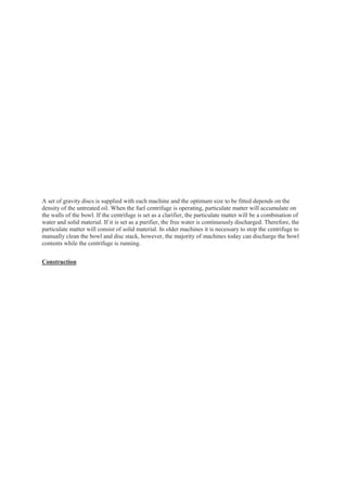
This document discusses lube oil purifiers and their operation. It provides details on two common purification methods - batch and continuous processes. It also describes the components and working of a disk-type, non-self-cleaning purifier used aboard a ship for continuous purification. Key points covered include how centrifugal force separates contaminants from oil and the importance of properly sized discharge rings for different oil densities.


![[Next Section] [Contents] [Info]
Direct comments to William Haynes whaynes@maritime.edu
Mon, Jul 1, 1996
TSPS Engineering Manual ©1995 Massachusetts Maritime](https://image.slidesharecdn.com/lubeoilpurifier-231231030218-27816f81/85/Lube-Oil-Purifier-docx-8-320.jpg)


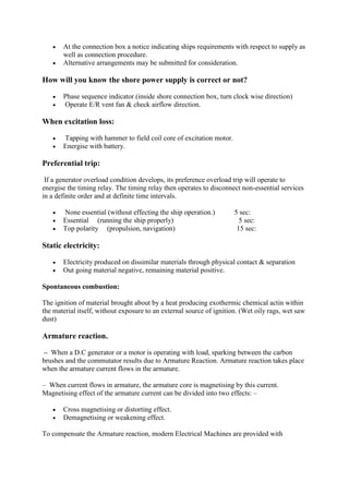


![ The CO2 from the pilot cylinders will open the system’s main stop valve.
The main stop valve has a piston which gets depressed due to the Co2 gas pressure
and allows the pilot gas to flow to the bank of CO2 cylinders.
This pilot gas operates the cylinders’ valves. All these valves have an actuator which
gets operated by the pilot pressure.
The detection of fire is done by various sensors installed in the machinery
spaces.Though the opening of control box operates an alarm, the main decision for
CO2 flooding is taken by the Chief engineer, after due consultation with the master of
the ship.
Before releasing Co2 into the fire affected space, it should be made sure that
everybody is out of the place and total head should be counted.
The place is fully enclosed i.e all skylights & ventilators are closed air-tight and
pumpsumps supplying fuel oil should also be stopped in order to prevent re-ignition.
Separate levers for each and every space are present inside the main controlling
cabinet. The operating of a particular lever activates the pilot bottles, which helps in
releasing the complete bank of bottles designated for that place.
With the opening of the master valve, Co2 is flooded inside the fire affected space,
which then smothers the fire with the help of blanket effect.
Boundary cooling should be carried out.
Machinery space minimum requirement:
1. Two nos. of fire hydrants with hoses, minimum.
2. 10 ft³ of sand and sawdust with scoops.
3. One fixed installation of CO₂ or foam or Halon.
4. Portable extinguishers of at least 2 nos. of 2 ½ gallon (11.37 litres) foam or CO₂,
depending on BHP.
5. Semi-portable extinguishers of 45 kgs of CO₂.
6. Drip pans and trays for every F.O. and L.O. tanks.
7. Monitoring, detection and alarm system.
8. Emergency fire pump.
9. 2 nos: of main fire pumps.
10. International shore connection.
11. Inert gas system.
Machinery space fire fighting: by CO₂ flooding system:
1. CO₂ flooding to machinery space must be done by master’s order.
2. CO₂ must be released by competent engineer, CE.
3. When cabinet door is opened alarm will sound and all ER fans will be stopped.
4. Before releasing, all ER crew to be counted.
5. All openings must be shut [ventilator flaps, fire damper].
6. All fuel pumps and quick closing valves of fuel tanks and fuel transfer line must be shut
from remote control position.
7. After opening the cabinet door, master valve must be opened first.
8. Pull the operating handle of pilot cylinders.
9. CO₂ , released from pilot cylinder, operate the gang release bar so that all CO₂ from quick
release or total flooding cylinders will be released to machinery space.
10. By regulation, 85% of the capacity must be able to be released within 2 minutes.](https://image.slidesharecdn.com/lubeoilpurifier-231231030218-27816f81/85/Lube-Oil-Purifier-docx-126-320.jpg)

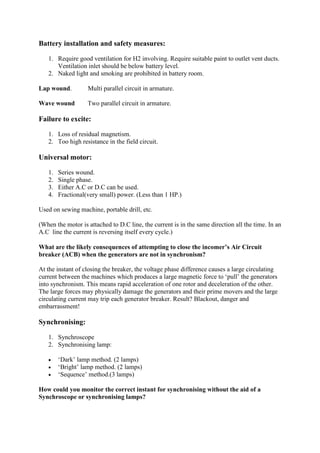
![1. Remote detector fitted at the bridge can detect concerned cargo space.
2. This operation must be done by master’s order.
3. After ensuring no person left in cargo space, seal off the cargo space [closing of ventilation
fan, fire damper, hatch cover].
4. Before discharging, change 3-way valve to CO₂ discharge line so that connection to smoke
detector is isolated.
5. Open the quick opening valve so that alarm will automatically initiated.
6. Manual operation procedure and amount of CO₂ bottle to be released is stated in CO₂
room.
7. By master’s order, release the correct amount to concerned cargo space.
8. Topping up procedure must be followed at port arrival.
Safety devices on CO2 flooding system:
1. Master valve with alarm switch.
2. Relief valves at manifold.
3. Stop valve and pull handle are in lock release cabinet and alarm switch.
4. Safety bursting disc at each CO2 bottle.
5. Leakage detecting pressure switch on manifold.
6. Non return discharge valves after CO2 bottles.
Requirements of CO2 bottles:
1. All bottles stamped at 52 bar pressure.
2. Bursting disc fitted, operates at 177~ 193 bar at 63 °C
3. Store in temperature less than 55 °C
4. Recharge if 5 % loss.
5. Clamped against movement and vibration(by wooden plank).
6. Remote and manual operation possible.
7. Hydraulically tested to 228 bar.
8. Level tested (by radio active level indication).
9. if > 10 years internal and external examination required.
General inspections in CO2 room:
1. Check emergency light and all other lights.
2. Check exhaust fan / ventilation.
3. Check all bottles overall condition, clamps, valves etc.
4. Check operating wire condition.
5. Check CO2 alarms.
6. CO2 room key should be in position.
7. Check the operating instructions.
8. Inspection to be recorded in log book and Saturday safety routine book.
Survey on CO2 flooding system:
1. Check CO2 weight every 2 years
2. Testing of cylinder at 228 bars
3. Blow through the lines
4. General inspection on Instructions, Key, Emergency lights, Ventilation, Alarms etc.](https://image.slidesharecdn.com/lubeoilpurifier-231231030218-27816f81/85/Lube-Oil-Purifier-docx-128-320.jpg)


![4. Pressure: sufficient to supply water of 40 ft horizontal throw, from 2 numbers of ½ ”
dia. water jets, from hoses of standard size and length, which are connected to any
part of the ship.
5. Total suction head and net positive suction head shall be such that, minimum 25 m³/hr
capacity, 2 water jets of 40 ft horizontal throw, shall be obtained, under all conditions
of list, trim, roll and pitch.
6. If diesel engine driven:
It is self-cooled.
Easily started in cold condition [0°C] by hand cranking.
Fuel service tank must have sufficient capacity for at least 3-hour operation, full
load.
Sufficient reserves available outside machinery space, for additional 15-
hour, full load.
7. If motor driven:
Two sources of power supply provided.
Power operated emergency fire pump, with source of power and sea connection, must
be located outside machinery space.
Sprinkler System:
1. By Regulation, passenger ships carrying more than 36 persons shall be provided with
Automatic Sprinkler System.
2. Generally used only to protect living quarters, passageways and public spaces.
Operation:
1. Each sprinkler head provided with a quartzoid valve, which seals the outlet of water pipe.
2. Valve is partially filled with special fluid, so that a rise in room temperature will expand
the liquid and the valve will burst.
3. Water under pressure; will flow out from Sprinkler System. ( 5 – 8 bars pressure is
maintained in FW pressure tank by air pressure.)
4. Sprinkler head can cover a floor area of about 12m² with water pressure of 5 – 8 bars.
5. Pressure drop in tank activates the pumps to take over and supply water from FW holding
tank. When holding tank become empty, SW pumps come into action automatically.
Regulations
1. No: of heads not more than 200 per section.
2. Heads are spaced not more than 4 meters apart.
3. At least 2 sources of power supply to Automatic alarm system and SW pump.
Advantages:
1. Self fire detection, and immediate and automatic operation at all time
2. Not harmful to human.
3. No need to seal the space.
4. No need to clean the media, after use.](https://image.slidesharecdn.com/lubeoilpurifier-231231030218-27816f81/85/Lube-Oil-Purifier-docx-131-320.jpg)

![1. Activate fire alarm or emergency alarm, as soon as noticing of breakout of fire.
2. Find the origin of fire, CE and all ER members informed.
3. Restrict it, and extinct it on the spot with portable extinguishers and by other means.
4. Verify the class of fire and decide the type of extinguishing agents, which should be used.
5. Initial attack must be backed-up with second more substantial means of attack.
[i.e. Semi-portable or Fire main, follows after portable ones.]
6. Water must be used prudently, since ship’s stability can be affected.
7. Fixed installation is a back-up, used as a last resort. Usage of fixed installation in ER fire
can cause loss of power and steering, for a long period of times.
8. Fixed fire fighting installation system can be used as initial attack on cargo hold fire.
9. Fire must be confined to the space, in which originated; [by controlling flow of air, by
cooling adjacent bulkheads, and by directing extinguishing agents onto fire].
10. Finally after fire is out, overhauling begins, and check structural damages.
11. All fire fighting equipment replenished.
12. Cause of fire to be determined, and action taken to prevent reoccurrence of same type of
fire.
If fire is considerable and immense:
1. Sound fire alarm system.
2. Evacuate all ER staff, count them and assign them as per Muster List.
3. Remote stopping of all fuel pumps, to be done.
4. Remote closing of all quick closing valves, to be done.
5. Remote closing of all skylight doors and ER watertight doors, to be done.
6. Remote closing of all ER ventilation dampers, to be done.
7. Prime mover and all machinery to be stopped.
8. All ER entry and exit doors, to be closed perfectly.
9. All ER ventilation fans, to be stopped manually.
10. Fixed installation system, to be operated by CE or 2/E in proper manner.
Fixed fire Detection and Alarm System:
a) This system with manual call points must be able to operate immediately at all times.
b) Must have two sources of power supply, and visual and audible alarms for power failure.
c) Control panel should be located on Bridge.
d) Heat, smoke or other products of combustion, flame or any combination of these may
operate detector.
Types of Detector:
Smoke detector:
1. Installed at stairways, corridor, escape route within Accommodation Space.
2. Also used in Cargo space and Machinery space
3. Maximum floor area per detector = 74 m².
4. Max. distance apart = 11 meters.
5. Max. distance away from bulkhead = 5.5 m.
6. Photocell or light scattering types.
Heat Detector:
1. Maximum floor area per detector = 37 m².](https://image.slidesharecdn.com/lubeoilpurifier-231231030218-27816f81/85/Lube-Oil-Purifier-docx-133-320.jpg)
![Extinguishing:
1. Two independently driven power pumps and one emergency pump driven by own engine
with delivering capacity of at least 25 m³ / hr. each.
2. Two hydrants (port and starboard) with spray nozzle fitted hose. (Minimum water pressure
37 psi.)
3. International shore connection [outside 7″ or 178 mm: inside 2 ½ ” or 64 mm].
4. CO₂ fixed installation which delivers 85% of gas within 2 minutes.
(Total weight of CO₂ per bottle: 100 lbs. or 45 kgs.)
5. Six nos. portable extinguishers (2 gal or 9.09 litres Foam 2 nos.,
2 gal Soda Acid 2 nos., 13 lbs or 6 kgs CO₂ 2 nos.)
6. 10 gal froth type extinguisher 1 no.
7. 10 ft³ of sand in the box.
Usage of the above mentioned equipment:
Oil fire: sand, foam, water spray
Combustible material: water, chemical foam, soda acid
Electrical: CO₂ gas and dry powder
Fire control plan:
1. General arrangement plan must be permanently exhibited onboard, for the guidance of
officers.
2. Positioned outside the deck house [opposite to gangway of both sides] in a
permanently watertight enclosure for assistance of shore fire brigade.
3. Fire Control Plan includes:
Fire control stations.
Various fire sections, enclosed by both Class A and Class B divisions.
Particulars of fire detection and alarm system.
Sprinkler installation and fire extinguishing appliance.
Means of escape.
Ventilation system, including positions and numbers of fan controls and dampers.
Fire Fighting Appliances (FFA):
1. All portable and semi-portable extinguishers: Good working order ensured, properly
placed in ER and always made handy.
2. Fixed fire fighting installation: Alarm testing and function testing once a week,
compressed air blowing of lines and discharge nozzles, contents to be weighed and checked
periodically.
3. Emergency fire pump: Good working order ensured, weekly test run without failure.
4. Fire detection, monitoring and alarm system: Tested weekly without any failure.
5. All fire hydrants and their connection, sand boxes and scoops: Kept in good working order.
6. Fire man’s outfits: 2 numbers in good working order and handy at all times.
7. International shore connection: Placed at proper location.
8. All ER members: Properly educated about fire fighting appliances and their operation.
9. Fire drill: Carried out at least once a month.
Safety Equipment:](https://image.slidesharecdn.com/lubeoilpurifier-231231030218-27816f81/85/Lube-Oil-Purifier-docx-135-320.jpg)
![1. Portable fire extinguishers.
2. Semi-portable fire extinguishers.
3. Fixed installation.
4. Detection and monitoring of fire.
5. Alarm signalling of fire.
6. Fire man’s outfits:
– Personnel equipment; an axe, lifeline, protective clothing, rigid helmet, safety lamp
(oxygen content meter), portable electric drill, boots and gloves.
– Breathing Apparatus; at least 2 nos: to be provided.
7. Emergency fire pump: With 2 additional main fire pumps (Sanitary, Ballast, Bilge or GS
pump), not normally used for pumping oil fuel. Suitable changeover arrangement fitted, if
they are occasionally used for pumping oil.
8. Fire hoses, nozzles of 12mm/16mm/19mm diameter [spray/jet type] and their container
box.
9. Escape ways, at least two nos.
10. Emergency generator.
11. Emergency lighting system (24V DC & 220V/110V AC).
12. Inert gas system.
13. Steering gear.
14. Communication system between bridge to ER, and to steering gear room.
15. Remote closing and stopping of fuel tanks, fuel pumps, ventilation fans, skylight door,
watertight doors, and fire dampers.
16. International shore connection.
17. Lifeboat, Life raft, Life buoy and Life jacket with illuminating source.
18. Navigation lighting (port and starboard, Main mast, Fore mast, Stern, Anchor).
19. Pilot ladder and lighting.
20. Gyro compass, Echo sounder, Direction finder, Radar and its alarm system.
21. Distress signal flares at least 12 numbers.
22. First aid kit.
23. Signalling apparatus (daylight signal, light and power source, Forecastle bell, Gong and
ship whistles, Fog horn).
ER Fire Fighting Media:
For boiler room:
1. At least 2 Portable Foam Extinguishers
2. 135 litres Foam Extinguisher
3. 1 Portable Foam Applicator with 20 litres spares tank.
4. One Sand box with a scoop.
For ER
1. At least 1 Portable Foam Applicator with 200 lb. spare container.
2. At least 45 litres Foam Extinguisher
3. At least 2 Portable Foam Extinguishers shall be placed within, not more than 10 meter
walking distance.
For ER Control Room:
1. Sufficient number of CO₂ Portable Fire Extinguishers.
Portable fire extinguishers:](https://image.slidesharecdn.com/lubeoilpurifier-231231030218-27816f81/85/Lube-Oil-Purifier-docx-136-320.jpg)
![1. Capacity of portable fluid extinguisher: ≯ 13.5 litres and ≮ 9 litres.
2. Other extinguisher: at least as portable as 13.5 litres fluid extinguisher and fire
extinguishing capability at least equivalent to that of 9 litres fluid extinguisher.
3. Ships of 1000 tons gross tonnage and upwards, shall carry at least 5 portable fire
extinguishers.
4. In boiler room:
a) At least 2 portable foam type extinguishers.
b) At least 1 foam type extinguisher of 135 litres capacity minimum, with hoses on reels,
reaching any part of boiler room.
c) A box of 10 ft³ of sand or other approved dry material with scoop.
d) One set of portable foam applicator unit with one spare 20 litre tank.
5. In space containing internal combustion machinery:
a) Sufficient no. of 45 litre capacity foam type extinguishers, to enable foam to be directed
onto fuel and LO pressure system, gearing and other fire hazards.
b) Sufficient no. of portable foam type extinguishers, so located that, there shall be at least 2
such extinguishers within 10- meter walking distance.
6. In space containing steam turbine:
a) Sufficient no. of 45-litre capacity foam type extinguishers, to enable foam to be directed
onto LO pressure system, turbine casing, gearing and other fire hazards.
b) However, such extinguishers shall be omitted, if protection is given by fixed installation.
c) Sufficient no. of portable foam type extinguishers, so located that, there shall be at least 2
such extinguishers within 10- meter walking distance.
Personal Life Saving Appliances:
1. Life buoys
2. Life jackets
3. Immersion suits
4. Thermal protective aids.
Fireman’s outfit:
Consists of:
Personal equipment, comprising protective clothing, boots and gloves of rubber, a
rigid helmet, an electric safety lamp [min burning period 3 hrs.], and an axe.
A breathing apparatus. Smoke Helmet [Smoke mask] or Self-contained compressed
air BA set.
Smoke helmet (Smoke mask) BA set:
a) Provided with suitable air pump.
b) An air hose exceeding 2 m in length, but not more than 36m.](https://image.slidesharecdn.com/lubeoilpurifier-231231030218-27816f81/85/Lube-Oil-Purifier-docx-137-320.jpg)


![7. International Oil Pollution Prevention Certificate
8. International Sewage Pollution Prevention Certificate
9. International Safety Management Certificate, SMC
10. International Medical Certificate
11. Passenger Ship Safety Certificate
12. Cargo Ship Safety Construction Certificate, SAFCON
13. Cargo Ship Safety Equipment Certificate, SEC
14. Cargo Ship Safety Radio Certificate
15. Exemption Certificates for SAFCON, SEC and Radio Certificate
16. Certificate of Classification
17. Certificate of Insurance or other financial security in respect of civil liability for oil
pollution damage
18. International Pollution Prevention Certificate for the Carriage of Noxious Liquid
Substances in Bulk. [NLS Certificate]
19. Certificate of Fitness for the Carriage of Dangerous Chemicals in Bulk
(Chemical Tanker)
20. Certificate of Fitness for the Carriage of Liquefied Gases in Bulk
(Gas Carrier)
SOLAS Certificates:
1. Passenger Ship Safety Certificate
2. Cargo Ship Safety Construction Certificate
3. Cargo Ship Safety Equipment Certificate
4. Cargo Ship Safety Radio Certificate
5. Cargo Ship Safety Certificate 1
6. Exemption Certificate
7. Document of Compliance with the special Requirements for Ships carrying
Dangerous Goods
8. Minimum Safe Manning Document
9. Document of Authorization for the Carriage of Grain
10. International Certificate of Fitness for the Carriage of Dangerous Chemicals in Bulk
11. International Certificate of Fitness for the Carriage of Liquefied Gases in Bulk
12. International Certificate of Fitness for the Carriage of INF Cargo
13. Safety Management Certificate (ISM)
14. Document of Compliance (ISM)
15. High Speed Craft Safety Certificate
16. International Ship Security Certificate
MARPOL Certificates:
MARPOL Annex I:
1. International Oil Pollution Prevention Certificate (IOPP Certificate)
2. Statement of Compliance with CAS (as a supplement to ship’s IOPP Certificate)
MARPOL Annex II:
1. International Certificate of Fitness for the Carriage of Dangerous Chemicals in Bulk
2. Certificate of Fitness for the Carriage of Dangerous Chemicals in Bulk](https://image.slidesharecdn.com/lubeoilpurifier-231231030218-27816f81/85/Lube-Oil-Purifier-docx-140-320.jpg)


![Lubrication in ice. ppt 4 [autosaved]](https://cdn.slidesharecdn.com/ss_thumbnails/lubricationinice-210526071608-thumbnail.jpg?width=640&height=640&fit=bounds)