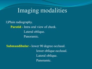
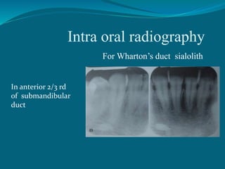
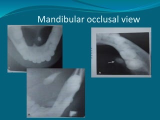
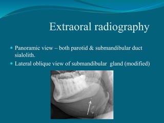
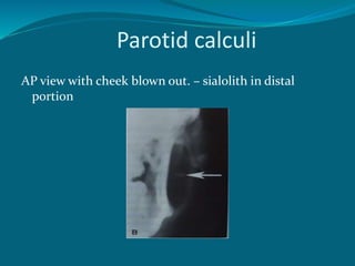
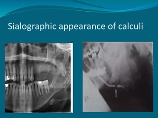
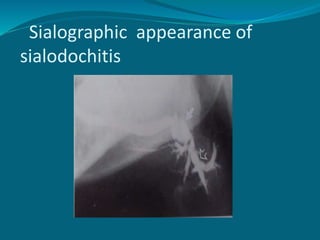
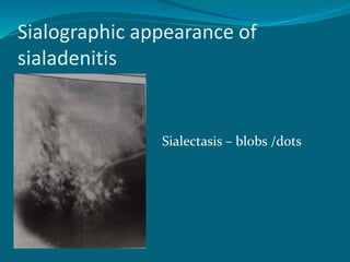
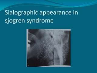
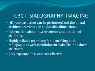
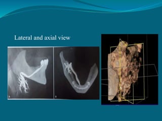
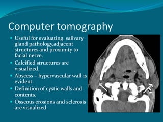
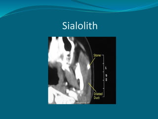
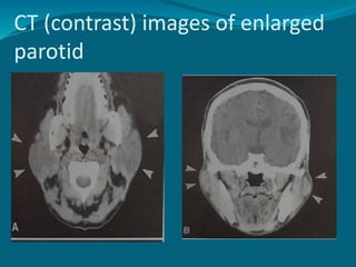
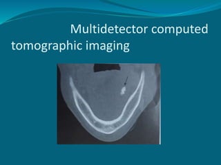
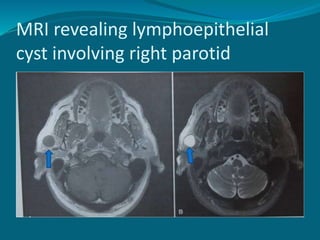
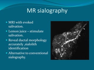
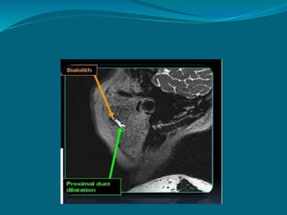
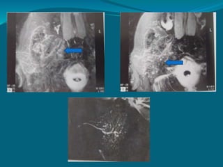
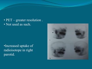
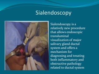
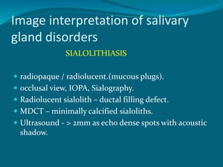
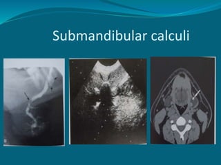
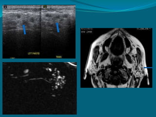
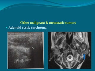
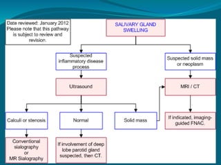
This document discusses the anatomy, imaging, and clinical evaluation of the salivary glands. It describes the major and minor salivary glands and lists common salivary gland complaints such as sialolithiasis, infection, Sjogren's syndrome, and tumors. Imaging modalities for evaluating salivary glands are discussed, including intraoral radiography, sialography, ultrasound, CT, MRI, scintigraphy, and sialendoscopy. The document provides examples of how various salivary gland pathologies appear on different imaging tests.
IDEAL IMAGE CHARACTERISTICS
FACTORS RELATED TO THE RADIATION BEAM
FACTORS RELATED TO THE OBJECT
FACTORS RELATED TO THE TECHNIQUE
FACTORS RELATED TO RECORDING OF THE ROENTGEN IMAGE OF THE OBJECT
DARK/ LIGHT IMAGE IDEAL IMAGE
IDEAL QUALITY CRIETRIA
IDEAL IMAGE CHARACTERISTICS
FACTORS RELATED TO THE RADIATION BEAM
FACTORS RELATED TO THE OBJECT
FACTORS RELATED TO THE TECHNIQUE
FACTORS RELATED TO RECORDING OF THE ROENTGEN IMAGE OF THE OBJECT
DARK/ LIGHT IMAGE IDEAL IMAGE
IDEAL QUALITY CRIETRIA
brief description about CONTENTS Introduction Principles of panoramic imaging Image layer Panoramic machines Panoramic film Patient positioning Interpreting the panoramic imaging INDICATION Advantages Disadvantages Conclusion References
3. INTRODUCTION • Panoramic imaging also called pantomography is a technique for producing a single tomographic image of facial structures that includes both the maxillary and mandibular dental arches and their supporting structures . • This is a curvilinear variant of conventional tomography.
4. PRINCIPLES OF PANORAMIC IMAGE FORMATION • Patero and Numata - describe the principles of panoramic radiography • based on the principle of reciprocal movement of x-ray source and an image receptor around a central point or plane called the image layer, in which the OBJECT of image is located. • OBJECT in front or behind this image are not clearly captured because of their movement relative to the centre of rotation of the receptor and the x-ray source.
5. The film and x-ray tubehead move around the patient in opposite directions in panoramic radiography
6. ROTATION CENTER The pivotal point or axis around which the cassette carrier and tube head rotate is termed rotation center Three basic rotation center used in panoramic radiography Double centre rotation Triple centre rotation moving centre rotation The location and number of rotational centers INFLUENCE size and shape of focal trough
7. IMAGE LAYER • Also known as focal trough • It is a three dimensional curved zone where the structures lying within this layer are reasonably well defined on final panoramic image. • The structures seen on a panoramic image are primarily those located within image layer. • OBJECTSoutside the image layer are blurred magnified are reduced in size. Even distorted to the extent of not being recognizable. • This shape of image layer varies with the brand of equipment used.
8. FOCAL TROUGH
9. FACTORS AFFECTING SIZE OF IMAGE LAYER: Arc path Velocity of receptor and X-ray tube head Alignment of x-ray beam Collimator width The location of image layer change with extensive machine used so recalibration may be necessary if consistently suboptimal images are produced. As a position of object is moved within the image layer size and shape of image layer change.
10. PANORAMIC UNIT
11. A, Orthophos XG Plus extraoral x-ray machine. B, Orthoralix 8500 extraoral x-ray machine. C, Example of a digital panoramic system
12. PARTS OF PANORAMIC UNITS a. x-ray tube head b. head positioner: chin rest notched bite block forehead rest lateral head support c. exposure controls
13. X-RAY TUBE HEAD: • Similar to intraoral x-ray tube head • Each has a filament to produce electrons and a target to produce x-rays • Collimator is a lead plate with narrow vertical slit • Narrow x-ray beam emerges from collimator minimize patient exposure to radiation
1
This presentation will give you a detailed knowledge about the various techniques that can be performed for imaging various aspects and diseases of TM Joint.
The Indian Dental Academy is the Leader in continuing dental education , training dentists in all aspects of dentistry and
offering a wide range of dental certified courses in different formats.
New Explore Careers and College Majors 2024.pdfDr. Mary Askew
Explore Careers and College Majors is a new online, interactive, self-guided career, major and college planning system.
The career system works on all devices!
For more Information, go to https://bit.ly/3SW5w8W
This comprehensive program covers essential aspects of performance marketing, growth strategies, and tactics, such as search engine optimization (SEO), pay-per-click (PPC) advertising, content marketing, social media marketing, and more
The Impact of Artificial Intelligence on Modern Society.pdfssuser3e63fc
Just a game Assignment 3
1. What has made Louis Vuitton's business model successful in the Japanese luxury market?
2. What are the opportunities and challenges for Louis Vuitton in Japan?
3. What are the specifics of the Japanese fashion luxury market?
4. How did Louis Vuitton enter into the Japanese market originally? What were the other entry strategies it adopted later to strengthen its presence?
5. Will Louis Vuitton have any new challenges arise due to the global financial crisis? How does it overcome the new challenges?Assignment 3
1. What has made Louis Vuitton's business model successful in the Japanese luxury market?
2. What are the opportunities and challenges for Louis Vuitton in Japan?
3. What are the specifics of the Japanese fashion luxury market?
4. How did Louis Vuitton enter into the Japanese market originally? What were the other entry strategies it adopted later to strengthen its presence?
5. Will Louis Vuitton have any new challenges arise due to the global financial crisis? How does it overcome the new challenges?
18. Conventional Sialography
Defined as radiographic demonstration of major salivary
glands by introducing a radiopaque contrast medium into
their ductal system.
Stones & strictures.
First - 1902
The preoperative phase
The filling phase.
The emptying phase.
19. Preoperative phase:
scout radiographs.
Position of radiopaque obstruction.
Position of normal anatomical structures.
Exposure factors.
23. Simple injection technique:
oil based /aqueous contrast media .
Gentle hand pressure till tightness /discomfort is felt.
Parotid – 1 ml,submandibular – 0.8 ml.
Simple & cheap.
Arbitary pressure - under or over filling due to patient
response.
24. Hydrostatic technique
Aqueous contrast media – overhead reservoir under
force of gravity.
Simple ,inexpensive.
Pt lying position and position for filling phase
radiographs.
25. Continuous infusion pressure monitored
technique:
Aqueous contrast media and ductal pressure monitored.
No damage/overfilling of gland.
Independent of pt response.
Complex equipment.
Time consuming.
26. Emptying phase:
Removal of cannula & pt asked to rinse.
Lemon juice aids in excretion.
Emptying phase radiographs.
28. Contrast agents in sialography
Iodine based
Ionic aqueous solution
Diatrizoate(urografin).
Metrizoate(triosil).
Non ionic aqueous solution
Iohexol (omniopaque).
Oil based solution
Iodized oil (lipiodol)
Water insoluble organic iodine compounds(pantopaque).
29. Indications:
1)The presence of calculi
2)To assess extent of ductal & glandular destruction.
3)To determine the extend of glandular breakdown and
crude assessment of function.
Contraindication:
1)Allergic to iodine compounds.
2)Acute infections
3)Calculus close to the ductal opening.
30. The main pathological changes are:
Ductal changes associated with –
Calculi
Sialodochitis (ductal inflammation).
Glandular changes associated with –
Sialadenitis.(glandular inflammation).
Sjogren syndrome.
Intrinsic tumours.
37. CBCT imaging
Useful for evaluating structures in & adjacent to
salivary gland
Cannot resolve soft tissue densities.
Minimal calcified sialolith well depicted.
Three D visualization possible.
38.
39. CBCT SIALOGRAPHY IMAGING
3D reconstruction can be performed and the ductal
architecture viewed in all possible dimensions.
Information about measurements and location of
sialoliths.
Highly reliable technique for identifying both
radiopaque as well as radiolucent sialoliths and ductal
strictures.
Less exposure dose and cost effective.
41. Computer tomography
Useful for evaluating salivary
gland pathology,adjacent
structures and proximity to
facial nerve.
Calcified structures are
visualized.
Abscess – hypervascular wall is
evident.
Definition of cystic walls and
contents.
Osseous erosions and sclerosis
are visualized.
47. MR sialography
MRI with evoked
salivation.
Lemon juice – stimulate
salivation.
Reveal ductal morphology
accurately ,sialolith
identification
Alternative to conventional
sialography.
48.
49.
50. Advantages
Ionizing radiation not used.
Excellent soft tissue details.
Differentiate benign & malignant.
Identify facial n.
Images in all planes.
Co- localization with PET scans.
MR sialography – no contrast.
MR spectroscopy – differentiate tissues by chemical
constituents.
In acute stage & cannulation not possible.
55. Advantages
Ionisation radiation not used.
Good imaging of superficial masses.
Differentiates solid & cystic masses.
Different echo signals from different tumours
Blood flow assessment using colour doppler.
Identify radiolucent stones.
Lithotripsy of salivary stones.
Ultra sound aided fine needle aspiration.
Intraoral US possible with small probes.
Differentiates intra and extra glandular masses.
57. Scintigraphy (Nuclear medicine, PET)
Functional study of salivary glands.
Iv injection of technetium 99m pertechnetate –
concentrated in and excreated by glandular structures
(salivary, thyroid,mammary ).
Appearance in ducts max. 30 to 45 min.
Sialagogue administered to evaluate secretory capacity.
major salivary glands studied at once.
High diagnostic sensitivity but lacks specificity.
Pathosis – increased/decreased/absent radionuclide
uptake.
58. • PET – greater resolution .
• Not used as such.
•Increased uptake of
radioisotope in right
parotid.
59. Sialendoscopy
Sialendoscopy is a
relatively new procedure
that allows endoscopic
transluminal
visualization of major
salivary gland ductal
system and offers a
mechanism for
diagnosing and treating
both inflammatory and
obstructive pathology
related to ductal system
66. Bacterial sialadenitis
Sialography contraindicated in acute infections.
Chronic cases – Sialectasia
(sac like acinar areas).
Abscess - seen in
MDCT,US,MRI.
67. Sialodochitis
Ductal sialadenitis.
Sialography – sausage string appearance (interstitial
fibrosis).
Seen in MRI.
Scintigraphy & CT not indicated.
68. Autoimmune Sialadenitis
Sialography is helpful.
Early stage – punctate (<1 mm) & globular (1-2 mm)
collection of contrast media – sialectasia.
Cavitary sialectases - larger & irregular suggestive of
advanced stage.
MRI – multiple punctate sialectases.
US – multiple hypoechoic areas.
69.
70. Sialadenosis
It is a non neoplastic,noninflammatory
enlargment of parotid gland.
Sialography - enlargement /normal appearance.
CT & MRI – straightforward depiction but are
nonspecific.
71. Cystic lesions
Ultrasound - cyst are sharply marginated and echo
free areas.
Well circumscribed ,high signal areas on T 2 weighted
MRI.
72.
73. Benign tumors
Well defined radiolucency - in CT & MRI.
Contrast agents in CT - >radiopaque due to increased
vascularity of tumor.
MRI - for submandibular gland neoplasm due to
superior soft tissue resolution.
USG – benign masses are less echogenic than
parenchyma.
Sialography – ball in hand.
74. Pleomorphic adenoma
MDCT – sharply circumscribed ,round homogenous
lesion with high density than adjacent tissue.
MRI - dark in T 1 weighted images, intermediate in
proton density weighted images & homogenous high
intensity in T 2 weighted images.
Signal voids – calcification present.
83. Conclusion
Imaging of the salivary glands uses many different
modalities .
no established absolute algorithm as to which study
should be performed.
Depends upon the radiologist preference.
84. References
1)Oral Radiology Principles and Interpretation.Stuart
White,Micheal Pharoah.
2)Salivary gland disorders.Eugene Myers,Robert Ferris.
3)Oral and Maxillo facial radiology. Freny Karjodkar.
4)Textbook of colour atlas of salivary gland
pathology.Eric Carlson,Robert Ford.
5)Atlas of oral diagnostic imaging.Tomomitsu Higashi.
6) Taneja et al. Salivary gland imaging.IJMDS.
7)Yousem et al.Major salivary gland imaging.Radiology.