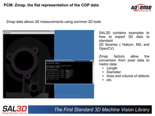
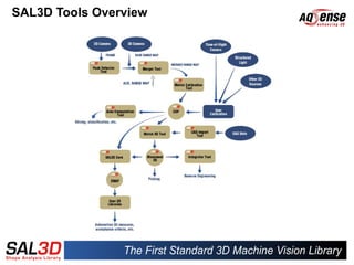
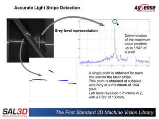
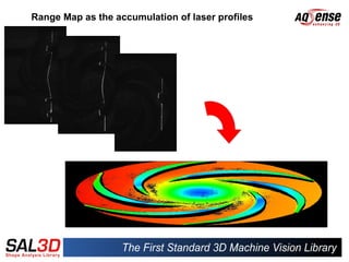
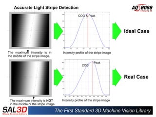
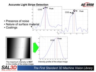
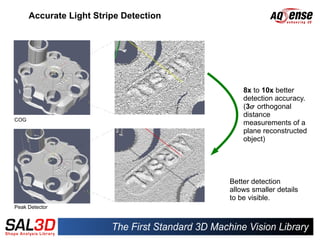
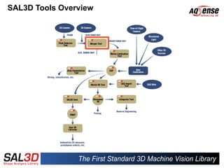
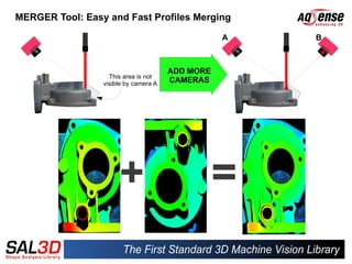
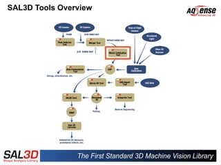
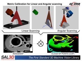
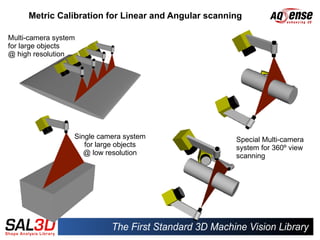
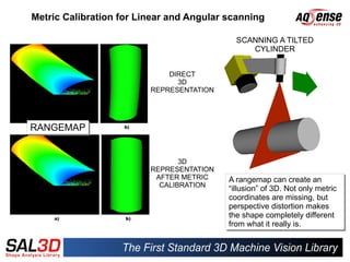
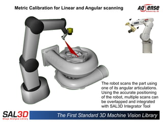
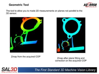
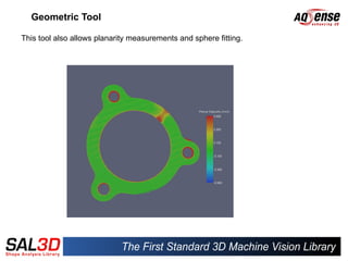
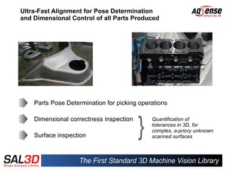
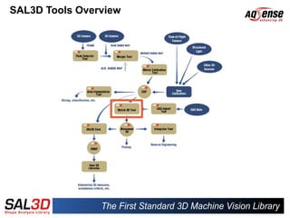
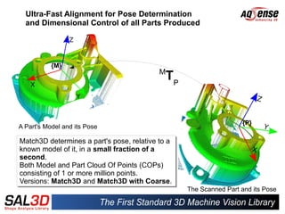
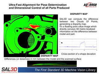
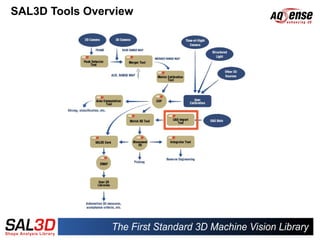
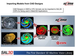
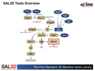
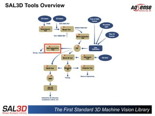
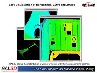
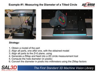
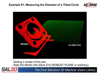
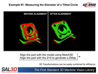
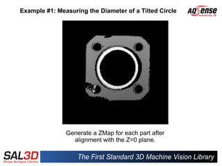
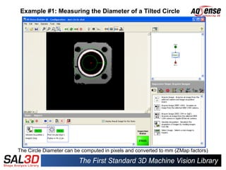
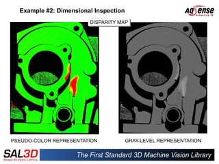
Dedicated Software
Algorithms for 3D Clouds of
          Points
Introduction


AQSENSE develops and commercializes 3D image acquisition and processing
technologies that allow high speed in-line 100% production inspection, for the
                           Machine Vision Industry.
Were are we ?


Parc Científic i Tecnològic de la UdG - 17003 Girona (Catalonia - Spain)
Presentation Outline


Part I: SAL3D PCM
     ✔ The ZMap as a “FLAT” representation of a COP


Part II: SAL3D Tools Overview
   ✔ Accurate Light Stripe Detection
   ✔ Easy and Fast Profiles Merging

   ✔ Metric Calibration for Linear and Angular Scanning

   ✔ Measuring Geometric Primitives

   ✔ Ultra-Fast Alignment for Pose Determination and Dimensional Control

   ✔ Importing Models from CAD Designs

   ✔ Integrating Multiple 3D Views into a Single Mesh

   ✔ Easy Visualization of Rangemaps, COPs and ZMaps


Part III: Applications Examples
   ✔ Measuring the Diameter of a Tilted Circle
   ✔ Dimensional Inspection
PART I
SAL3D Point Cloud
 Manager (PCM)
Point Cloud Manager (PCM)
Tool for management for 3D data: COPs and ZMaps


     COP: Organized container for 3D data coming from different
     sources:

      ●   Laser triangulation
      ●   Time-of-flight
      ●   Structured Light
      ●   Stereo vision
PCM: Zmap, the flat representation of the COP data


                                        Orthogonal projection
                                          onto the Z plane


 A COP is an organized set of 3D
  A COP is an organized set of 3D                        A ZMap is the projection of a COP
                                                          A ZMap is the projection of a COP
 points, expressed in X, Y and Z
  points, expressed in X, Y and Z                        onto the Z=0 plane.
                                                          onto the Z=0 plane.
 coordinates.
  coordinates.                                           Its
                                                          Its   horizontal
                                                                 horizontal   and
                                                                              and    vertical
                                                                                      vertical
 It's like a set of 3 “images” of
  It's like a set of 3 “images” of                       coordinates are proportional to the
                                                          coordinates are proportional to the
 floating
  floating      point
                point      numbers,
                           numbers,                      actual X and Y coordinates of the
                                                          actual X and Y coordinates of the
 representing the X, Y and Z sets of
  representing the X, Y and Z sets of                    COP, while its contents are the Z
                                                          COP, while its contents are the Z
 coordinates
  coordinates                                            coordinate values.
                                                          coordinate values.
The ZMap as a “FLAT” representation of a COP

                                           Rangemap     ZMap

Rangemap vs. ZMap


Preserves metric properties                  NO         YES
Independent of acquisition source            NO         YES
Can be used by 2D tools                   SOMETIMES    ALWAYS
Can be used to locate 3D features using
2D tools, in 3D space                     INDIRECTLY    YES
Removes perspective distortion               NO         YES
PCM: Zmap, the flat representation of the COP data


 Zmap data allows 3D measurements using common 2D tools


                                                     SAL3D contains examples to
                                                     how to export 3D data to
                                                     standard
                                                     2D libraries ( Halcon, MIL and
                                                     OpenCV).

                                                     Zmap      factors  allow    the
                                                     conversion from pixel data to
                                                     metric data:
                                                       ●  Length
                                                       ●  Diameter
                                                       ●  Area and volume of defects
                                                       ●  etc.
PART II
SAL3D Tools Overview
Accurate Light Stripe Detection


                   Grey level representation
                                                             Determination
                                                             of the maximum
                                                             value position
                                                             up to 1/64th of
                                                             a pixel


                                      A single point is obtained for each
                                      line across the laser stripe.
                                      This point is obtained at subpixel
                                      accuracy at a maximum of 1/64
                                      pixel.
                                      Lab tests revealed 5 microns in Z,
                                      with a FOV of 130mm.
Range Map as the accumulation of laser profiles
Accurate Light Stripe Detection
                                                  COG & Peak


                                                                              Ideal Case


The maximum intensity is in           Intensity profile of the stripe image
the middle of the stripe image.

                                                              Peak
                                                     COG


                                                                              Real Case


 The maximum intensity is NOT         Intensity profile of the stripe image
 in the middle of the stripe image.
Accurate Light Stripe Detection
                                                      Peak
                                         COG
                                                                                 Peak
                                                                     PeakCOG
                                                              COG


● Presence of noise
● Nature of surface material

● Coatings


                                                                 Peak
                                                        COG


    The maximum intensity is NOT         Intensity profile of the stripe image
    in the middle of the stripe image.
Accurate Light Stripe Detection

                      Light stripe
                      detection


                                            8x to 10x better
                                            detection accuracy.
                                            (3 orthogonal
                                            distance
COG
                                            measurements of a
                                            plane reconstructed
                                            object)


                                        Better detection
                                        allows smaller details
                                        to be visible.
Peak Detector
SAL3D Tools Overview
MERGER Tool: Easy and Fast Profiles Merging

                                                  A   B


                                       ADD MORE
                   This area is not
                 visible by camera A   CAMERAS
SAL3D Tools Overview
Metric Calibration for Linear and Angular scanning


             Linear Scanning                 Angular Scanning


     RANGEMAP                           CLOUD OF POINTS (COP)
Metric Calibration for Linear and Angular scanning

Multi-camera system
for large objects
@ high resolution


                  Single camera system               Special Multi-camera
                     for large objects               system for 360º view
                     @ low resolution                scanning
Metric Calibration for Linear and Angular scanning

                                            SCANNING A TILTED
                                               CYLINDER


                             DIRECT
                               3D
                         REPRESENTATION


RANGEMAP
RANGEMAP


                                3D
                         REPRESENTATION
                          AFTER METRIC    A rangemap can create an
                           CALIBRATION
                                           A rangemap can create an
                                          “illusion” of 3D. Not only metric
                                           “illusion” of 3D. Not only metric
                                          coordinates are missing, but
                                           coordinates are missing, but
                                          perspective distortion makes
                                           perspective distortion makes
                                          the shape completely different
                                           the shape completely different
                                          from what it really is.
                                           from what it really is.
Metric Calibration for Linear and Angular scanning


                                       The robot scans the part using
                                       one of its angular articulations.
                                       Using the accurate positioning
                                       of the robot, multiple scans can
                                       be overlapped and integrated
                                       with SAL3D Integrator Tool
Geometric Tool

The tool to allow you to made 2D measurements on planes not parallel to the
3D sensor.


     Zmap from the acquired COP
                                                  Zmap after plane fitting and
                                                correction on the acquired COP
Geometric Tool

This tool also allows planarity measurements and sphere fitting.
Ultra-Fast Alignment for Pose Determination
and Dimensional Control of all Parts Produced


    Parts Pose Determination for picking operations

    Dimensional correctness inspection       Quantification of
                                             tolerances in 3D, for
                                             complex, a-priory unknown
    Surface inspection                       scanned surfaces
SAL3D Tools Overview
Ultra-Fast Alignment for Pose Determination
  and Dimensional Control of all Parts Produced


           {M}
                                          M
                                            TP


                                                                   {P}
A Part's Model and its Pose

Match3D determines a part's pose, relative to a
known model of it, in a small fraction of a
second.
second.
Both Model and Part Cloud Of Points (COPs)
consisting of 1 or more million points.
Versions: Match3D and Match3D with Coarse.
                                                  The Scanned Part and its Pose
Ultra-Fast Alignment for Pose Determination
    and Dimensional Control of all Parts Produced

                                                               DISPARITY MAP

                                                     SAL3D can compute the difference
                                                     between two Clouds Of Points,
                                                     generating a disparity map.
                                                     It's a floating point value image which
                                                     directly conveys 3D metric localized
                                                     information on the difference between
                                                     model and part.


                                                      Cross-section of a shape deviation
                                    DISPARITY MAP
Differences (or distances) in mm between the model and the scanned surface
SAL3D Tools Overview
Importing Models from CAD Designs

     CAD Designs in IGES or STL formats can be imported to SAL3D
     CAD Designs in IGES or STL formats can be imported to SAL3D
     COPs for being used in Match3D Applications
     COPs for being used in Match3D Applications
SAL3D Tools Overview
Integrating Multiple 3D Views into a Single Mesh


                                            Single mesh after integration


Multiple views aligned and overlapped


  A Mesh can be stored as a .PLY or
  .STL file with a simple function call.

  Reverse Engineering, Rapid Prototyping,
  Archeology, etc...
SAL3D Tools Overview
Area Computation Tool


                                             Applications
                                              ●   Volume measure
                                              ●    Density checking: With the help of the
    Area with respects to a reference line        Area Tool the volume of an object is
                                                  obtained. Then, knowing its weight, the
                                                  density can be easily calculated
                                              ●    Slicing: When automatically slicing food
                                                  to be packed, neither extra material is
                                                  desired nor can fewer product be given
                                                  to the user. Computing the piece volume
                                                  allows a precise cut with the exact
                                                  weight.


            Area of a closed
            profile
Easy Visualization of Rangemaps, COPs and ZMaps


SAL3D allows the instantiation of viewer windows with their corresponding controls
PART III
Application Examples
Example #1: Measuring the Diameter of a Tilted Circle


Strategy:

1. Obtain a model of the part
2. Align all parts, one after one, with the obtained model
3. Align all parts to the Z=0 plane, using
4. Generate a ZMap and feed into a 2D circle measurement tool
5. Compute the hole diameter (in pixels)
6. Convert the diameter in pixels into millimeters using the ZMap factors
Example #1: Measuring the Diameter of a Tilted Circle


        MODEL                                PLANE Z=0


   Getting a model of the part
   Align the Model with plane Z=0 (ROBUST PLANE or arbitrary)
Example #1: Measuring the Diameter of a Tilted Circle


           BEFORE ALIGNMENT      AFTER ALIGNMENT


        Align the part with the model using Match3D
        Align the part with the model using Match3D
        Align the part with the Z=0 to generate a ZMap
        Align the part with the Z=0 to generate a ZMap

                       3D Transformations can be easily combined for efficiency
Example #1: Measuring the Diameter of a Tilted Circle


               Generate a ZMap for each part after
                 alignment with the Z=0 plane.
Example #1: Measuring the Diameter of a Tilted Circle


The Circle Diameter can be computed in pixels and converted to mm (ZMap factors)
Example #2: Dimensional Inspection
                        DISPARITY MAP
                        DISPARITY MAP


PSEUDO-COLOR REPRESENTATION            GRAY-LEVEL REPRESENTATION
Example #2: Dimensional Inspection

Disparity Map
Example #2: Dimensional Inspection

Disparity Map
          Binarization
Example #2: Dimensional Inspection

Disparity Map
          Binarization
                    Blob segmentation by size
Example #2: Dimensional Inspection

Disparity Map                                   mmPerGrayLevel = 0.024
          Binarization
                    Blob segmentation by size


                                                                         mm


                                                         Gray Level
SUMMARY


 SAL3D as a C++ Standard Library or integrated in CVB.

 SAL3D technology is proven and present in different industries
 such as Food, Dental, Metal, ...

 SAL3D technologies cover a very wide range of 3D MV applications.

 Ease of Use, Robustness, Accuracy and Speed are the four
 pillars of AQSENSE's Technologies, embedded in SAL3D.

 SAL3D can be easily combined with Standard 2D Machine Vision
 Libraries to enable a huge number of applications.

SAL3D presentation - AQSENSE's 3D machine vision library

  • 1.
  • 2.
    Introduction AQSENSE develops andcommercializes 3D image acquisition and processing technologies that allow high speed in-line 100% production inspection, for the Machine Vision Industry.
  • 3.
    Were are we? Parc Científic i Tecnològic de la UdG - 17003 Girona (Catalonia - Spain)
  • 4.
    Presentation Outline Part I:SAL3D PCM ✔ The ZMap as a “FLAT” representation of a COP Part II: SAL3D Tools Overview ✔ Accurate Light Stripe Detection ✔ Easy and Fast Profiles Merging ✔ Metric Calibration for Linear and Angular Scanning ✔ Measuring Geometric Primitives ✔ Ultra-Fast Alignment for Pose Determination and Dimensional Control ✔ Importing Models from CAD Designs ✔ Integrating Multiple 3D Views into a Single Mesh ✔ Easy Visualization of Rangemaps, COPs and ZMaps Part III: Applications Examples ✔ Measuring the Diameter of a Tilted Circle ✔ Dimensional Inspection
  • 5.
    PART I SAL3D PointCloud Manager (PCM)
  • 6.
    Point Cloud Manager(PCM) Tool for management for 3D data: COPs and ZMaps COP: Organized container for 3D data coming from different sources: ● Laser triangulation ● Time-of-flight ● Structured Light ● Stereo vision
  • 7.
    PCM: Zmap, theflat representation of the COP data Orthogonal projection onto the Z plane A COP is an organized set of 3D A COP is an organized set of 3D A ZMap is the projection of a COP A ZMap is the projection of a COP points, expressed in X, Y and Z points, expressed in X, Y and Z onto the Z=0 plane. onto the Z=0 plane. coordinates. coordinates. Its Its horizontal horizontal and and vertical vertical It's like a set of 3 “images” of It's like a set of 3 “images” of coordinates are proportional to the coordinates are proportional to the floating floating point point numbers, numbers, actual X and Y coordinates of the actual X and Y coordinates of the representing the X, Y and Z sets of representing the X, Y and Z sets of COP, while its contents are the Z COP, while its contents are the Z coordinates coordinates coordinate values. coordinate values.
  • 8.
    The ZMap asa “FLAT” representation of a COP Rangemap ZMap Rangemap vs. ZMap Preserves metric properties NO YES Independent of acquisition source NO YES Can be used by 2D tools SOMETIMES ALWAYS Can be used to locate 3D features using 2D tools, in 3D space INDIRECTLY YES Removes perspective distortion NO YES
  • 9.
    PCM: Zmap, theflat representation of the COP data Zmap data allows 3D measurements using common 2D tools SAL3D contains examples to how to export 3D data to standard 2D libraries ( Halcon, MIL and OpenCV). Zmap factors allow the conversion from pixel data to metric data: ● Length ● Diameter ● Area and volume of defects ● etc.
  • 10.
  • 11.
  • 12.
  • 13.
    Accurate Light StripeDetection Grey level representation Determination of the maximum value position up to 1/64th of a pixel A single point is obtained for each line across the laser stripe. This point is obtained at subpixel accuracy at a maximum of 1/64 pixel. Lab tests revealed 5 microns in Z, with a FOV of 130mm.
  • 14.
    Range Map asthe accumulation of laser profiles
  • 15.
    Accurate Light StripeDetection COG & Peak Ideal Case The maximum intensity is in Intensity profile of the stripe image the middle of the stripe image. Peak COG Real Case The maximum intensity is NOT Intensity profile of the stripe image in the middle of the stripe image.
  • 16.
    Accurate Light StripeDetection Peak COG Peak PeakCOG COG ● Presence of noise ● Nature of surface material ● Coatings Peak COG The maximum intensity is NOT Intensity profile of the stripe image in the middle of the stripe image.
  • 17.
    Accurate Light StripeDetection Light stripe detection 8x to 10x better detection accuracy. (3 orthogonal distance COG measurements of a plane reconstructed object) Better detection allows smaller details to be visible. Peak Detector
  • 18.
  • 19.
    MERGER Tool: Easyand Fast Profiles Merging A B ADD MORE This area is not visible by camera A CAMERAS
  • 20.
  • 21.
    Metric Calibration forLinear and Angular scanning Linear Scanning Angular Scanning RANGEMAP CLOUD OF POINTS (COP)
  • 22.
    Metric Calibration forLinear and Angular scanning Multi-camera system for large objects @ high resolution Single camera system Special Multi-camera for large objects system for 360º view @ low resolution scanning
  • 23.
    Metric Calibration forLinear and Angular scanning SCANNING A TILTED CYLINDER DIRECT 3D REPRESENTATION RANGEMAP RANGEMAP 3D REPRESENTATION AFTER METRIC A rangemap can create an CALIBRATION A rangemap can create an “illusion” of 3D. Not only metric “illusion” of 3D. Not only metric coordinates are missing, but coordinates are missing, but perspective distortion makes perspective distortion makes the shape completely different the shape completely different from what it really is. from what it really is.
  • 24.
    Metric Calibration forLinear and Angular scanning The robot scans the part using one of its angular articulations. Using the accurate positioning of the robot, multiple scans can be overlapped and integrated with SAL3D Integrator Tool
  • 25.
    Geometric Tool The toolto allow you to made 2D measurements on planes not parallel to the 3D sensor. Zmap from the acquired COP Zmap after plane fitting and correction on the acquired COP
  • 26.
    Geometric Tool This toolalso allows planarity measurements and sphere fitting.
  • 27.
    Ultra-Fast Alignment forPose Determination and Dimensional Control of all Parts Produced Parts Pose Determination for picking operations Dimensional correctness inspection Quantification of tolerances in 3D, for complex, a-priory unknown Surface inspection scanned surfaces
  • 28.
  • 29.
    Ultra-Fast Alignment forPose Determination and Dimensional Control of all Parts Produced {M} M TP {P} A Part's Model and its Pose Match3D determines a part's pose, relative to a Match3D determines a part's pose, relative to a known model of it, in a small fraction of a known model of it, in a small fraction of a second. second. Both Model and Part Cloud Of Points (COPs) Both Model and Part Cloud Of Points (COPs) consisting of 1 or more million points. consisting of 1 or more million points. Versions: Match3D and Match3D with Coarse. Versions: Match3D and Match3D with Coarse. The Scanned Part and its Pose
  • 30.
    Ultra-Fast Alignment forPose Determination and Dimensional Control of all Parts Produced DISPARITY MAP SAL3D can compute the difference between two Clouds Of Points, generating a disparity map. It's a floating point value image which directly conveys 3D metric localized information on the difference between model and part. Cross-section of a shape deviation DISPARITY MAP Differences (or distances) in mm between the model and the scanned surface
  • 31.
  • 32.
    Importing Models fromCAD Designs CAD Designs in IGES or STL formats can be imported to SAL3D CAD Designs in IGES or STL formats can be imported to SAL3D COPs for being used in Match3D Applications COPs for being used in Match3D Applications
  • 33.
  • 34.
    Integrating Multiple 3DViews into a Single Mesh Single mesh after integration Multiple views aligned and overlapped A Mesh can be stored as a .PLY or .STL file with a simple function call. Reverse Engineering, Rapid Prototyping, Archeology, etc...
  • 35.
  • 36.
    Area Computation Tool Applications ● Volume measure ● Density checking: With the help of the Area with respects to a reference line Area Tool the volume of an object is obtained. Then, knowing its weight, the density can be easily calculated ● Slicing: When automatically slicing food to be packed, neither extra material is desired nor can fewer product be given to the user. Computing the piece volume allows a precise cut with the exact weight. Area of a closed profile
  • 37.
    Easy Visualization ofRangemaps, COPs and ZMaps SAL3D allows the instantiation of viewer windows with their corresponding controls
  • 38.
  • 39.
    Example #1: Measuringthe Diameter of a Tilted Circle Strategy: 1. Obtain a model of the part 2. Align all parts, one after one, with the obtained model 3. Align all parts to the Z=0 plane, using 4. Generate a ZMap and feed into a 2D circle measurement tool 5. Compute the hole diameter (in pixels) 6. Convert the diameter in pixels into millimeters using the ZMap factors
  • 40.
    Example #1: Measuringthe Diameter of a Tilted Circle MODEL PLANE Z=0 Getting a model of the part Align the Model with plane Z=0 (ROBUST PLANE or arbitrary)
  • 41.
    Example #1: Measuringthe Diameter of a Tilted Circle BEFORE ALIGNMENT AFTER ALIGNMENT Align the part with the model using Match3D Align the part with the model using Match3D Align the part with the Z=0 to generate a ZMap Align the part with the Z=0 to generate a ZMap 3D Transformations can be easily combined for efficiency
  • 42.
    Example #1: Measuringthe Diameter of a Tilted Circle Generate a ZMap for each part after alignment with the Z=0 plane.
  • 43.
    Example #1: Measuringthe Diameter of a Tilted Circle The Circle Diameter can be computed in pixels and converted to mm (ZMap factors)
  • 44.
    Example #2: DimensionalInspection DISPARITY MAP DISPARITY MAP PSEUDO-COLOR REPRESENTATION GRAY-LEVEL REPRESENTATION
  • 45.
    Example #2: DimensionalInspection Disparity Map
  • 46.
    Example #2: DimensionalInspection Disparity Map Binarization
  • 47.
    Example #2: DimensionalInspection Disparity Map Binarization Blob segmentation by size
  • 48.
    Example #2: DimensionalInspection Disparity Map mmPerGrayLevel = 0.024 Binarization Blob segmentation by size mm Gray Level
  • 49.
    SUMMARY SAL3D asa C++ Standard Library or integrated in CVB. SAL3D technology is proven and present in different industries such as Food, Dental, Metal, ... SAL3D technologies cover a very wide range of 3D MV applications. Ease of Use, Robustness, Accuracy and Speed are the four pillars of AQSENSE's Technologies, embedded in SAL3D. SAL3D can be easily combined with Standard 2D Machine Vision Libraries to enable a huge number of applications.