Problems in Enterprise Integration: Schematic Heterogeneities between Semanti...Amit Sheth
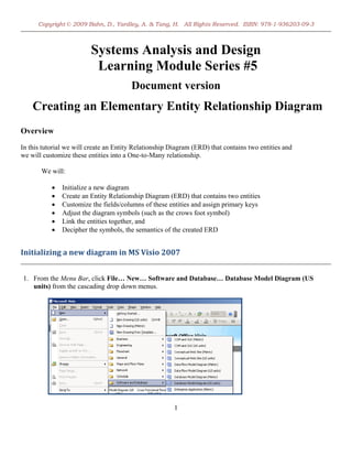
This is a subset of slides associated with:
A. Sheth and V. Kashyap, So Far (Schematically) yet So Near (Semantically), Invited paper in Proceedings of the IFIP TC2/WG2.6 Conference on Semantics of Interoperable Database Systems, DS-5, November 1992.
Data Modeling and Database Design 2nd Edition by Umanath Scamell Solution Manualendokayle
link full download: https://testbankstudy.com/product/data-modeling-and-database-design-2nd-edition-by-umanath-scamell-solution-manual/
Language: English
ISBN-10: 1285085256
ISBN-13: 978-1285085258
ISBN-13: 9781285085258
Problems in Enterprise Integration: Schematic Heterogeneities between Semanti...Amit Sheth
This is a subset of slides associated with:
A. Sheth and V. Kashyap, So Far (Schematically) yet So Near (Semantically), Invited paper in Proceedings of the IFIP TC2/WG2.6 Conference on Semantics of Interoperable Database Systems, DS-5, November 1992.
Data Modeling and Database Design 2nd Edition by Umanath Scamell Solution Manualendokayle
link full download: https://testbankstudy.com/product/data-modeling-and-database-design-2nd-edition-by-umanath-scamell-solution-manual/
Language: English
ISBN-10: 1285085256
ISBN-13: 978-1285085258
ISBN-13: 9781285085258
FellowBuddy.com is an innovative platform that brings students together to share notes, exam papers, study guides, project reports and presentation for upcoming exams.
We connect Students who have an understanding of course material with Students who need help.
Benefits:-
# Students can catch up on notes they missed because of an absence.
# Underachievers can find peer developed notes that break down lecture and study material in a way that they can understand
# Students can earn better grades, save time and study effectively
Our Vision & Mission – Simplifying Students Life
Our Belief – “The great breakthrough in your life comes when you realize it, that you can learn anything you need to learn; to accomplish any goal that you have set for yourself. This means there are no limits on what you can be, have or do.”
Like Us - https://www.facebook.com/FellowBuddycom
Database Systems Design, Implementation, and Manageme.docxtheodorelove43763
Database Systems:
Design, Implementation, and Management
Ninth Edition
Chapter 4
Entity Relationship (ER) Modeling
*
Database Systems, 9th Edition
*
ObjectivesIn this chapter, students will learn:The main characteristics of entity relationship componentsHow relationships between entities are defined, refined, and incorporated into the database design processHow ERD components affect database design and implementation
Database Systems, 9th Edition
Database Systems, 9th Edition
*
The Entity Relationship Model (ERM)ER model forms the basis of an ER diagramERD represents conceptual database as viewed by end userERDs depict database’s main components:EntitiesAttributesRelationships
Database Systems, 9th Edition
Database Systems, 9th Edition
*
EntitiesRefers to entity set and not to single entity occurrenceCorresponds to table and not to row in relational environmentIn Chen and Crow’s Foot models, entity is represented by rectangle with entity’s nameEntity name, a noun, written in capital letters
Database Systems, 9th Edition
Database Systems, 9th Edition
*
AttributesCharacteristics of entitiesChen notation: attributes represented by ovals connected to entity rectangle with a lineEach oval contains the name of attribute it representsCrow’s Foot notation: attributes written in attribute box below entity rectangle
Database Systems, 9th Edition
Database Systems, 9th Edition
*
Database Systems, 9th Edition
Database Systems, 9th Edition
*
Attributes (cont’d.)Required attribute: must have a valueOptional attribute: may be left emptyDomain: set of possible values for an attributeAttributes may share a domainIdentifiers: one or more attributes that uniquely identify each entity instanceComposite identifier: primary key composed of more than one attribute
Database Systems, 9th Edition
Database Systems, 9th Edition
*
Database Systems, 9th Edition
Database Systems, 9th Edition
*
Attributes (cont’d.)Composite attribute can be subdividedSimple attribute cannot be subdividedSingle-value attribute can have only a single valueMultivalued attributes can have many values
Database Systems, 9th Edition
Database Systems, 9th Edition
*
Database Systems, 9th Edition
Database Systems, 9th Edition
*
Attributes (cont’d.)M:N relationships and multivalued attributes should not be implementedCreate several new attributes for each of the original multivalued attributes’ componentsCreate new entity composed of original multivalued attributes’ componentsDerived attribute: value may be calculated from other attributesNeed not be physically stored within database
Database Systems, 9th Edition
Database Systems, 9th Edition
*
Database Systems, 9th Edition
Database Systems, 9th Edition
*
RelationshipsAssociation between entitiesParticipants are entities that participate in a relationshipRelationships between entities always operate in both directionsRelationship can be classified as 1:MRelationship classificati.
Analyzing and Visualizing Data Chapter 6Data Represent.docxdurantheseldine
Analyzing and Visualizing Data
Chapter 6
Data Representation
Introducing Visual Encoding
Data representation is the act of giving visual form to your data.
Viewers: When perceiving a visual display of data, it is decoded using the shapes, sizes, positions and colors to form an understanding
Visualizers: Doing the reverse through visual encoding, assigning visual properties to data values
Comprised of a combination of two properties
Marks: Visible features like dots, lines and areas
Attributes: Variations applied to the appearance of marks, such as size, position, or color.
Introducing Visual Encoding cont.
TBA
Introducing Visual Encoding cont.
TBA
Introducing Visual Encoding cont.
TBA
Introducing Visual Encoding cont.
TBA
Introducing Visual Encoding cont.
Marks and Attributes are the ingredients, a chart type is the recipe offering a predefined template for displaying data.
Different chart types offer different ways of representing data.
Introducing Visual Encoding cont.
TBA
Introducing Visual Encoding cont.
TBA
Introducing Visual Encoding cont.
TBA
Introducing Visual Encoding cont.
Chart Types
TBA
Chart Types
Exclusions
Inclusions
Categorical comparisons
Dual families
Text visualization
Dashboard
Small multiples
A note about ‘storytelling’
Influencing Factors and Considerations
TBA
Influencing Factors and Considerations cont.
TBA
Influencing Factors and Considerations cont.
TBA
Influencing Factors and Considerations cont.
TBA
Influencing Factors and Considerations cont.
TBA
Influencing Factors and Considerations cont.
TBA
Influencing Factors and Considerations cont.
TBA
Influencing Factors and Considerations cont.
TBA
Influencing Factors and Considerations cont.
TBA
Influencing Factors and Considerations cont.
TBA
Influencing Factors and Considerations cont.
TBA
Influencing Factors and Considerations cont.
TBA
Analyzing and Visualizing Data
Selecting a Graph
Selecting a Graph
Pie Charts
Compare a certain sector to the total.
Useful when there are only two sectors, for example yes/no or queued/finished.
Instant understanding of proportions when few sectors are used as dimensions.
When you use 10 sectors, or less, the pie chart keeps its visual efficiency.
Selecting a Graph cont.
Bar Charts/Plots
Ordinal and nominal data sets
Compare things between different groups or to track changes over time
Measure change over time, bar graphs are best when the changes are larger
Display and compare the number, frequency or other measure (e.g. mean) for different discrete categories of data
Flexible chart type and there are several variations of the standard bar chart including horizontal bar charts, grouped or component charts, and stacked bar charts.
Frequency for each category of a categorical variable
Relative frequency (%) for each category
Select.
Fundamentals of database system - Data Modeling Using the Entity-Relationshi...Mustafa Kamel Mohammadi
In this chapter you will learn
Relational data model concepts
What is entity?
What is attribute and it’s types
What is relationship?
What is an Entity-Relationship data model?
Relational data model constraints
Characteristics of relation
So Far (Schematically) yet So Near (Semantically)Amit Sheth
A. Sheth and V. Kashyap, So Far (Schematically) yet So Near (Semantically),
Keynote at the IFIP TC2/WG2.6 Conference on Semantics
of Interoperable Database Systems, DS-5, November 1992. http://knoesis.org/library/resource.php?id=1511
GDG Cloud Southlake #33: Boule & Rebala: Effective AppSec in SDLC using Deplo...James Anderson
Effective Application Security in Software Delivery lifecycle using Deployment Firewall and DBOM
The modern software delivery process (or the CI/CD process) includes many tools, distributed teams, open-source code, and cloud platforms. Constant focus on speed to release software to market, along with the traditional slow and manual security checks has caused gaps in continuous security as an important piece in the software supply chain. Today organizations feel more susceptible to external and internal cyber threats due to the vast attack surface in their applications supply chain and the lack of end-to-end governance and risk management.
The software team must secure its software delivery process to avoid vulnerability and security breaches. This needs to be achieved with existing tool chains and without extensive rework of the delivery processes. This talk will present strategies and techniques for providing visibility into the true risk of the existing vulnerabilities, preventing the introduction of security issues in the software, resolving vulnerabilities in production environments quickly, and capturing the deployment bill of materials (DBOM).
Speakers:
Bob Boule
Robert Boule is a technology enthusiast with PASSION for technology and making things work along with a knack for helping others understand how things work. He comes with around 20 years of solution engineering experience in application security, software continuous delivery, and SaaS platforms. He is known for his dynamic presentations in CI/CD and application security integrated in software delivery lifecycle.
Gopinath Rebala
Gopinath Rebala is the CTO of OpsMx, where he has overall responsibility for the machine learning and data processing architectures for Secure Software Delivery. Gopi also has a strong connection with our customers, leading design and architecture for strategic implementations. Gopi is a frequent speaker and well-known leader in continuous delivery and integrating security into software delivery.
Communications Mining Series - Zero to Hero - Session 1DianaGray10
This session provides introduction to UiPath Communication Mining, importance and platform overview. You will acquire a good understand of the phases in Communication Mining as we go over the platform with you. Topics covered:
• Communication Mining Overview
• Why is it important?
• How can it help today’s business and the benefits
• Phases in Communication Mining
• Demo on Platform overview
• Q/A
Generative AI Deep Dive: Advancing from Proof of Concept to ProductionAggregage
Join Maher Hanafi, VP of Engineering at Betterworks, in this new session where he'll share a practical framework to transform Gen AI prototypes into impactful products! He'll delve into the complexities of data collection and management, model selection and optimization, and ensuring security, scalability, and responsible use.
GraphSummit Singapore | The Art of the Possible with Graph - Q2 2024Neo4j
Neha Bajwa, Vice President of Product Marketing, Neo4j
Join us as we explore breakthrough innovations enabled by interconnected data and AI. Discover firsthand how organizations use relationships in data to uncover contextual insights and solve our most pressing challenges – from optimizing supply chains, detecting fraud, and improving customer experiences to accelerating drug discoveries.
Observability Concepts EVERY Developer Should Know -- DeveloperWeek Europe.pdfPaige Cruz
Monitoring and observability aren’t traditionally found in software curriculums and many of us cobble this knowledge together from whatever vendor or ecosystem we were first introduced to and whatever is a part of your current company’s observability stack.
While the dev and ops silo continues to crumble….many organizations still relegate monitoring & observability as the purview of ops, infra and SRE teams. This is a mistake - achieving a highly observable system requires collaboration up and down the stack.
I, a former op, would like to extend an invitation to all application developers to join the observability party will share these foundational concepts to build on:
Encryption in Microsoft 365 - ExpertsLive Netherlands 2024Albert Hoitingh
In this session I delve into the encryption technology used in Microsoft 365 and Microsoft Purview. Including the concepts of Customer Key and Double Key Encryption.
GraphRAG is All You need? LLM & Knowledge GraphGuy Korland
Guy Korland, CEO and Co-founder of FalkorDB, will review two articles on the integration of language models with knowledge graphs.
1. Unifying Large Language Models and Knowledge Graphs: A Roadmap.
https://arxiv.org/abs/2306.08302
2. Microsoft Research's GraphRAG paper and a review paper on various uses of knowledge graphs:
https://www.microsoft.com/en-us/research/blog/graphrag-unlocking-llm-discovery-on-narrative-private-data/
Removing Uninteresting Bytes in Software FuzzingAftab Hussain
Imagine a world where software fuzzing, the process of mutating bytes in test seeds to uncover hidden and erroneous program behaviors, becomes faster and more effective. A lot depends on the initial seeds, which can significantly dictate the trajectory of a fuzzing campaign, particularly in terms of how long it takes to uncover interesting behaviour in your code. We introduce DIAR, a technique designed to speedup fuzzing campaigns by pinpointing and eliminating those uninteresting bytes in the seeds. Picture this: instead of wasting valuable resources on meaningless mutations in large, bloated seeds, DIAR removes the unnecessary bytes, streamlining the entire process.
In this work, we equipped AFL, a popular fuzzer, with DIAR and examined two critical Linux libraries -- Libxml's xmllint, a tool for parsing xml documents, and Binutil's readelf, an essential debugging and security analysis command-line tool used to display detailed information about ELF (Executable and Linkable Format). Our preliminary results show that AFL+DIAR does not only discover new paths more quickly but also achieves higher coverage overall. This work thus showcases how starting with lean and optimized seeds can lead to faster, more comprehensive fuzzing campaigns -- and DIAR helps you find such seeds.
- These are slides of the talk given at IEEE International Conference on Software Testing Verification and Validation Workshop, ICSTW 2022.
Smart TV Buyer Insights Survey 2024 by 91mobiles.pdf91mobiles
91mobiles recently conducted a Smart TV Buyer Insights Survey in which we asked over 3,000 respondents about the TV they own, aspects they look at on a new TV, and their TV buying preferences.
DevOps and Testing slides at DASA ConnectKari Kakkonen
My and Rik Marselis slides at 30.5.2024 DASA Connect conference. We discuss about what is testing, then what is agile testing and finally what is Testing in DevOps. Finally we had lovely workshop with the participants trying to find out different ways to think about quality and testing in different parts of the DevOps infinity loop.
Elevating Tactical DDD Patterns Through Object CalisthenicsDorra BARTAGUIZ
After immersing yourself in the blue book and its red counterpart, attending DDD-focused conferences, and applying tactical patterns, you're left with a crucial question: How do I ensure my design is effective? Tactical patterns within Domain-Driven Design (DDD) serve as guiding principles for creating clear and manageable domain models. However, achieving success with these patterns requires additional guidance. Interestingly, we've observed that a set of constraints initially designed for training purposes remarkably aligns with effective pattern implementation, offering a more ‘mechanical’ approach. Let's explore together how Object Calisthenics can elevate the design of your tactical DDD patterns, offering concrete help for those venturing into DDD for the first time!
LF Energy Webinar: Electrical Grid Modelling and Simulation Through PowSyBl -...DanBrown980551
Do you want to learn how to model and simulate an electrical network from scratch in under an hour?
Then welcome to this PowSyBl workshop, hosted by Rte, the French Transmission System Operator (TSO)!
During the webinar, you will discover the PowSyBl ecosystem as well as handle and study an electrical network through an interactive Python notebook.
PowSyBl is an open source project hosted by LF Energy, which offers a comprehensive set of features for electrical grid modelling and simulation. Among other advanced features, PowSyBl provides:
- A fully editable and extendable library for grid component modelling;
- Visualization tools to display your network;
- Grid simulation tools, such as power flows, security analyses (with or without remedial actions) and sensitivity analyses;
The framework is mostly written in Java, with a Python binding so that Python developers can access PowSyBl functionalities as well.
What you will learn during the webinar:
- For beginners: discover PowSyBl's functionalities through a quick general presentation and the notebook, without needing any expert coding skills;
- For advanced developers: master the skills to efficiently apply PowSyBl functionalities to your real-world scenarios.