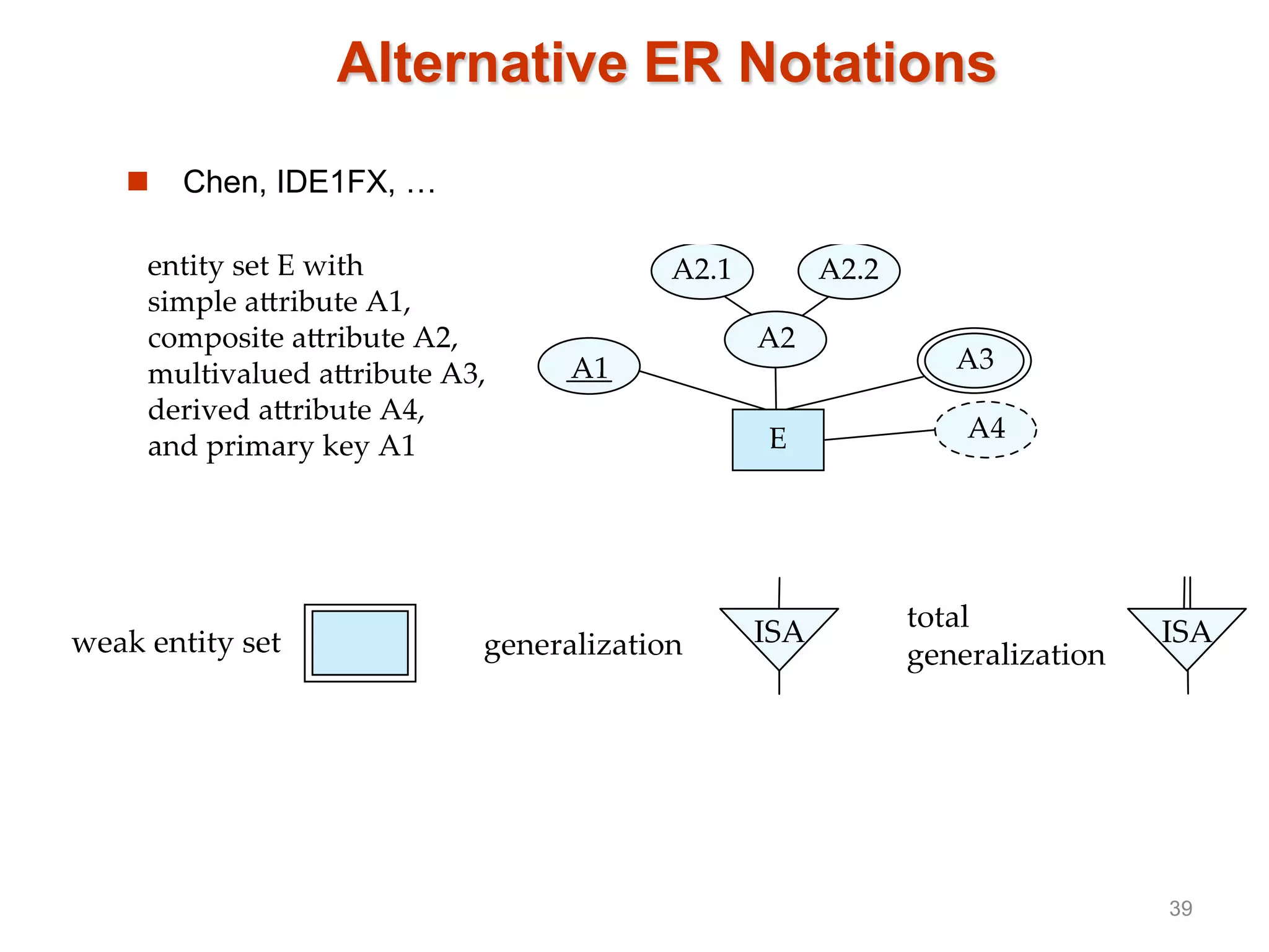
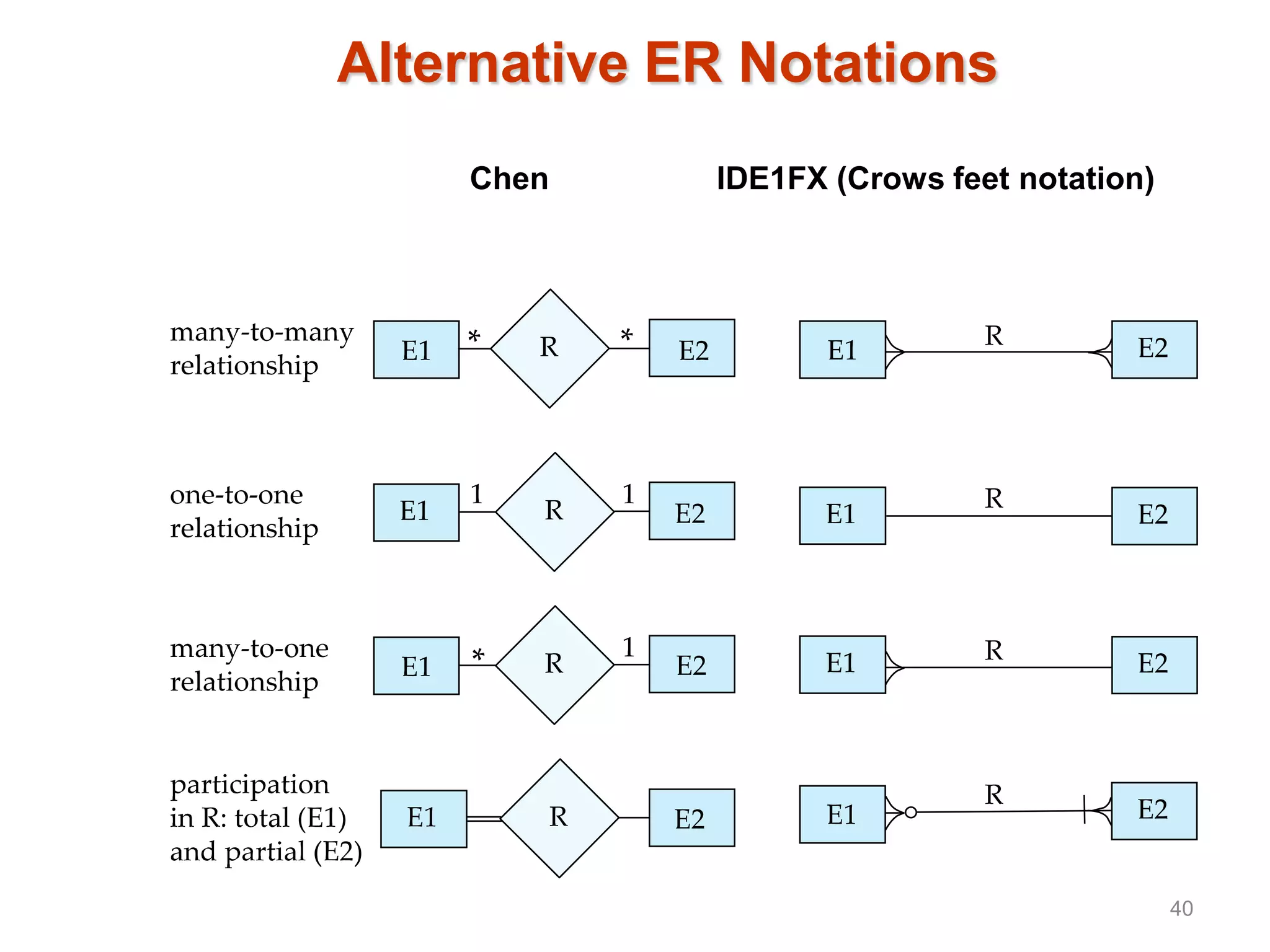
E-R Model (II)
1
Roadmap of This Lecture
 Weak Entity Sets
 Extended E-R Features
 Reduction to Relation Schemas
 Database Design
 UML*
2
Weak Entity Sets
 An entity set that does not have a primary key is referred to as a
weak entity set.
 The existence of a weak entity set depends on the existence of a
identifying entity set
 It must relate to the identifying entity set via a total, one-to-many
relationship set from the identifying to the weak entity set
 Identifying relationship depicted using a double diamond
 The discriminator (or partial key) of a weak entity set is the set of
attributes that distinguishes among all the entities of a weak entity
set.
 The primary key of a weak entity set is formed by the primary key of
the strong entity set on which the weak entity set is existence
dependent, plus the weak entity set’s discriminator.
3
Weak Entity Sets (Cont.)
 We underline the discriminator of a weak entity set with a dashed
line.
 We put the identifying relationship of a weak entity in a double
diamond.
 Primary key for section – (course_id, sec_id, semester, year)
4
Weak Entity Sets (Cont.)
 Note: the primary key of the strong entity set is not explicitly stored
with the weak entity set, since it is implicit in the identifying
relationship.
 If course_id were explicitly stored, section could be made a strong
entity, but then the relationship between section and course would
be duplicated by an implicit relationship defined by the attribute
course_id common to course and section
5
E-R Diagram for a University Enterprise
6
Reduction to Relational Schemas
7
Reduction to Relation Schemas
 Entity sets and relationship sets can be expressed uniformly as
relation schemas that represent the contents of the database.
 A database which conforms to an E-R diagram can be represented by
a collection of schemas.
 For each entity set and relationship set there is a unique schema that
is assigned the name of the corresponding entity set or relationship
set.
 Each schema has a number of columns (generally corresponding to
attributes), which have unique names.
8
Representing Entity Sets With Simple
Attributes
 A strong entity set reduces to a schema with the same attributes
student(ID, name, tot_cred)
 A weak entity set becomes a table that includes a column for the
primary key of the identifying strong entity set
section ( course_id, sec_id, sem, year )
9
Representing Relationship Sets
 A many-to-many relationship set is represented as a schema with
attributes for the primary keys of the two participating entity sets, and
any descriptive attributes of the relationship set.
 Example: schema for relationship set advisor
advisor = (s_id, i_id)
10
Redundancy of Schemas
 Many-to-one and one-to-many relationship sets that are total on the
many-side can be represented by adding an extra attribute to the
“many” side, containing the primary key of the “one” side
 Example: Instead of creating a schema for relationship set inst_dept,
add an attribute dept_name to the schema arising from entity set
instructor
11
Redundancy of Schemas (Cont.)
 For one-to-one relationship sets, either side can be chosen to act as
the “many” side
 That is, extra attribute can be added to either of the tables
corresponding to the two entity sets
 If participation is partial on the “many” side, replacing a schema by an
extra attribute in the schema corresponding to the “many” side could
result in null values
 The schema corresponding to a relationship set linking a weak entity
set to its identifying strong entity set is redundant.
 Example: The section schema already contains the attributes that
would appear in the sec_course schema
12
Composite and Multivalued Attributes
 Composite attributes are flattened out by creating
a separate attribute for each component attribute
 Example: given entity set instructor with
composite attribute name with component
attributes first_name and last_name the
schema corresponding to the entity set has
two attributes name_first_name and
name_last_name
 Prefix omitted if there is no ambiguity
 Ignoring multivalued attributes, extended instructor
schema is
 instructor(ID,
first_name, middle_initial, last_name,
street_number, street_name,
apt_number, city, state, zip_code,
date_of_birth)
13
Composite and Multivalued Attributes
 A multivalued attribute M of an entity E is represented by a separate
schema EM
 Schema EM has attributes corresponding to the primary key of E
and an attribute corresponding to multivalued attribute M
 Example: Multivalued attribute phone_number of instructor is
represented by a schema:
inst_phone= ( ID, phone_number)
 Each value of the multivalued attribute maps to a separate tuple of
the relation on schema EM
 For example, an instructor entity with primary key 22222 and
phone numbers 456-7890 and 123-4567 maps to two tuples:
(22222, 456-7890) and (22222, 123-4567)
14
Multivalued Attributes (Cont.)
 Special case:entity time_slot has only one attribute other than the
primary-key attribute, and that attribute is multivalued
 Optimization: Don’t create the relation corresponding to the entity,
just create the one corresponding to the multivalued attribute
 time_slot(time_slot_id, day, start_time, end_time)
 Caveat: time_slot attribute of section (from sec_time_slot) cannot
be a foreign key due to this optimization
15
Design Issues
 Use of entity sets vs. attributes
 Use of phone as an entity allows extra information about phone
numbers (plus multiple phone numbers)
16
Design Issues
 Use of entity sets vs. relationship sets
Possible guideline is to designate a relationship set to describe an
action that occurs between entities
17
Design Issues
 Binary versus n-ary relationship sets
Although it is possible to replace any nonbinary (n-ary, for n > 2)
relationship set by a number of distinct binary relationship sets, a n-
ary relationship set shows more clearly that several entities participate
in a single relationship.
 Placement of relationship attributes
e.g., attribute date as attribute of advisor or as attribute of student
18
Binary Vs. Non-Binary Relationships
 Some relationships that appear to be non-binary may be better
represented using binary relationships
 E.g., A ternary relationship parents, relating a child to his/her
father and mother, is best replaced by two binary relationships,
father and mother
 Using two binary relationships allows partial information (e.g.,
only mother being know)
 But there are some relationships that are naturally non-binary
 Example: proj_guide
19
Converting Non-Binary Relationships to Binary Form
 In general, any non-binary relationship can be represented using
binary relationships by creating an artificial entity set.
 Replace R between entity sets A, B and C by an entity set E, and
three relationship sets:
1. RA, relating E and A 2. RB, relating E and B
3. RC, relating E and C
 Create a special identifying attribute for E
 Add any attributes of R to E
 For each relationship (ai , bi , ci) in R, create
1. a new entity ei in the entity set E 2. add (ei , ai ) to RA
3. add (ei , bi ) to RB 4. add (ei , ci ) to RC
20
Converting Non-Binary Relationships
(Cont.)
 Also need to translate constraints
 Translating all constraints may not be possible
 There may be instances in the translated schema that
cannot correspond to any instance of R
 Exercise: add constraints to the relationships RA, RB and RC to
ensure that a newly created entity corresponds to exactly one
entity in each of entity sets A, B and C
 We can avoid creating an identifying attribute by making E a weak
entity set (described shortly) identified by the three relationship
sets
21
Extended ER Features
22
Extended E-R Features: Specialization
 Top-down design process; we designate subgroupings within an entity
set that are distinct from other entities in the set.
 These subgroupings become lower-level entity sets that have
attributes or participate in relationships that do not apply to the higher-
level entity set.
 Depicted by a triangle component labeled ISA (E.g., instructor “is a”
person).
 Attribute inheritance – a lower-level entity set inherits all the
attributes and relationship participation of the higher-level entity set to
which it is linked.
23
Specialization Example
24
Extended ER Features: Generalization
 A bottom-up design process – combine a number of entity sets that
share the same features into a higher-level entity set.
 Specialization and generalization are simple inversions of each other;
they are represented in an E-R diagram in the same way.
 The terms specialization and generalization are used interchangeably.
25
Specialization and Generalization (Cont.)
 Can have multiple specializations of an entity set based on different
features.
 E.g., permanent_employee vs. temporary_employee, in addition to
instructor vs. secretary
 Each particular employee would be
 a member of one of permanent_employee or
temporary_employee,
 and also a member of one of instructor or secretary
 The ISA relationship also referred to as superclass - subclass
relationship
26
Design Constraints on a
Specialization/Generalization
 Constraint on which entities can be members of a given lower-level
entity set.
 condition-defined
 Example: all customers over 65 years are members of senior-
citizen entity set; senior-citizen ISA person.
 user-defined
 Constraint on whether or not entities may belong to more than one
lower-level entity set within a single generalization.
 Disjoint
 an entity can belong to only one lower-level entity set
 Noted in E-R diagram by having multiple lower-level entity sets
link to the same triangle
 Overlapping
 an entity can belong to more than one lower-level entity set
27
Design Constraints on a
Specialization/Generalization (Cont.)
 Completeness constraint -- specifies whether or not an entity in the
higher-level entity set must belong to at least one of the lower-level
entity sets within a generalization.
 total: an entity must belong to one of the lower-level entity sets
 partial: an entity need not belong to one of the lower-level entity
sets
28
Aggregation
 Consider the ternary relationship proj_guide, which we saw earlier
 Suppose we want to record evaluations of a student by a guide on a
project
29
Aggregation (Cont.)
 Relationship sets eval_for and proj_guide represent overlapping
information
 Every eval_for relationship corresponds to a proj_guide
relationship
 However, some proj_guide relationships may not correspond to
any eval_for relationships
 So we can’t discard the proj_guide relationship
 Eliminate this redundancy via aggregation
 Treat relationship as an abstract entity
 Allows relationships between relationships
 Abstraction of relationship into new entity
30
Aggregation (Cont.)
 Without introducing redundancy, the following diagram represents:
 A student is guided by a particular instructor on a particular project
 A student, instructor, project combination may have an associated
evaluation
31
Representing Specialization via
Schemas
 Method 1:
 Form a schema for the higher-level entity set
 Form a schema for each lower-level entity set, include primary key
of higher-level entity set and local attributes
schema attributes
person ID, name, street, city
student ID, tot_cred
employee ID, salary
 Drawback: getting information about an employee requires
accessing two relations, the one corresponding to the low-level
schema and the one corresponding to the high-level schema
32
Representing Specialization as Schemas
(Cont.)
 Method 2:
 Form a schema for each entity set with all local and inherited
attributes
schema attributes
person ID, name, street, city
student ID, name, street, city, tot_cred
employee ID, name, street, city, salary
 If specialization is total, the schema for the generalized entity set
(person) not required to store information
 Can be defined as a “view” relation containing union of
specialization relations
 But explicit schema may still be needed for foreign key
constraints
 Drawback: name, street and city may be stored redundantly for
people who are both students and employees
33
Schemas Corresponding to Aggregation
 To represent aggregation, create a schema containing
 primary key of the aggregated relationship,
 the primary key of the associated entity set
 any descriptive attributes
34
Schemas Corresponding to Aggregation
(Cont.)
 For example, to represent aggregation eval_for between relationship
proj_guide and entity set evaluation, create a schema
eval_for (s_ID, project_id, i_ID, evaluation_id)
 Schema proj_guide is redundant provided we are willing to store null
values for attribute evaluation_id in relation on schema eval_for
35
E-R Design Decisions
 The use of an attribute or entity set to represent an object.
 Whether a real-world concept is best expressed by an entity set or a
relationship set.
 The use of a ternary relationship versus a pair of binary relationships.
 The use of a strong or weak entity set.
 The use of specialization/generalization – contributes to modularity in
the design.
 The use of aggregation – can treat the aggregate entity set as a single
unit without concern for the details of its internal structure.
36
Summary of Symbols Used in E-R
Notation
37
Symbols Used in E-R Notation (Cont.)
38
Alternative ER Notations
 Chen, IDE1FX, …
39
Alternative ER Notations
Chen IDE1FX (Crows feet notation)
40
UML
 UML: Unified Modeling Language
 UML has many components to graphically model different aspects of
an entire software system
 UML Class Diagrams correspond to E-R Diagram, but several
differences.
41
ER vs. UML Class Diagrams
*Note reversal of position in cardinality constraint depiction
42
ER vs. UML Class Diagrams
ER Diagram Notation Equivalent in UML
*Generalization can use merged or separate arrows independent
of disjoint/overlapping
43
UML Class Diagrams (Cont.)
 Binary relationship sets are represented in UML by just drawing a line
connecting the entity sets. The relationship set name is written
adjacent to the line.
 The role played by an entity set in a relationship set may also be
specified by writing the role name on the line, adjacent to the entity
set.
 The relationship set name may alternatively be written in a box, along
with attributes of the relationship set, and the box is connected, using
a dotted line, to the line depicting the relationship set.
44
End
45

L7 er2

  • 1.
  • 2.
    Roadmap of ThisLecture  Weak Entity Sets  Extended E-R Features  Reduction to Relation Schemas  Database Design  UML* 2
  • 3.
    Weak Entity Sets An entity set that does not have a primary key is referred to as a weak entity set.  The existence of a weak entity set depends on the existence of a identifying entity set  It must relate to the identifying entity set via a total, one-to-many relationship set from the identifying to the weak entity set  Identifying relationship depicted using a double diamond  The discriminator (or partial key) of a weak entity set is the set of attributes that distinguishes among all the entities of a weak entity set.  The primary key of a weak entity set is formed by the primary key of the strong entity set on which the weak entity set is existence dependent, plus the weak entity set’s discriminator. 3
  • 4.
    Weak Entity Sets(Cont.)  We underline the discriminator of a weak entity set with a dashed line.  We put the identifying relationship of a weak entity in a double diamond.  Primary key for section – (course_id, sec_id, semester, year) 4
  • 5.
    Weak Entity Sets(Cont.)  Note: the primary key of the strong entity set is not explicitly stored with the weak entity set, since it is implicit in the identifying relationship.  If course_id were explicitly stored, section could be made a strong entity, but then the relationship between section and course would be duplicated by an implicit relationship defined by the attribute course_id common to course and section 5
  • 6.
    E-R Diagram fora University Enterprise 6
  • 7.
  • 8.
    Reduction to RelationSchemas  Entity sets and relationship sets can be expressed uniformly as relation schemas that represent the contents of the database.  A database which conforms to an E-R diagram can be represented by a collection of schemas.  For each entity set and relationship set there is a unique schema that is assigned the name of the corresponding entity set or relationship set.  Each schema has a number of columns (generally corresponding to attributes), which have unique names. 8
  • 9.
    Representing Entity SetsWith Simple Attributes  A strong entity set reduces to a schema with the same attributes student(ID, name, tot_cred)  A weak entity set becomes a table that includes a column for the primary key of the identifying strong entity set section ( course_id, sec_id, sem, year ) 9
  • 10.
    Representing Relationship Sets A many-to-many relationship set is represented as a schema with attributes for the primary keys of the two participating entity sets, and any descriptive attributes of the relationship set.  Example: schema for relationship set advisor advisor = (s_id, i_id) 10
  • 11.
    Redundancy of Schemas Many-to-one and one-to-many relationship sets that are total on the many-side can be represented by adding an extra attribute to the “many” side, containing the primary key of the “one” side  Example: Instead of creating a schema for relationship set inst_dept, add an attribute dept_name to the schema arising from entity set instructor 11
  • 12.
    Redundancy of Schemas(Cont.)  For one-to-one relationship sets, either side can be chosen to act as the “many” side  That is, extra attribute can be added to either of the tables corresponding to the two entity sets  If participation is partial on the “many” side, replacing a schema by an extra attribute in the schema corresponding to the “many” side could result in null values  The schema corresponding to a relationship set linking a weak entity set to its identifying strong entity set is redundant.  Example: The section schema already contains the attributes that would appear in the sec_course schema 12
  • 13.
    Composite and MultivaluedAttributes  Composite attributes are flattened out by creating a separate attribute for each component attribute  Example: given entity set instructor with composite attribute name with component attributes first_name and last_name the schema corresponding to the entity set has two attributes name_first_name and name_last_name  Prefix omitted if there is no ambiguity  Ignoring multivalued attributes, extended instructor schema is  instructor(ID, first_name, middle_initial, last_name, street_number, street_name, apt_number, city, state, zip_code, date_of_birth) 13
  • 14.
    Composite and MultivaluedAttributes  A multivalued attribute M of an entity E is represented by a separate schema EM  Schema EM has attributes corresponding to the primary key of E and an attribute corresponding to multivalued attribute M  Example: Multivalued attribute phone_number of instructor is represented by a schema: inst_phone= ( ID, phone_number)  Each value of the multivalued attribute maps to a separate tuple of the relation on schema EM  For example, an instructor entity with primary key 22222 and phone numbers 456-7890 and 123-4567 maps to two tuples: (22222, 456-7890) and (22222, 123-4567) 14
  • 15.
    Multivalued Attributes (Cont.) Special case:entity time_slot has only one attribute other than the primary-key attribute, and that attribute is multivalued  Optimization: Don’t create the relation corresponding to the entity, just create the one corresponding to the multivalued attribute  time_slot(time_slot_id, day, start_time, end_time)  Caveat: time_slot attribute of section (from sec_time_slot) cannot be a foreign key due to this optimization 15
  • 16.
    Design Issues  Useof entity sets vs. attributes  Use of phone as an entity allows extra information about phone numbers (plus multiple phone numbers) 16
  • 17.
    Design Issues  Useof entity sets vs. relationship sets Possible guideline is to designate a relationship set to describe an action that occurs between entities 17
  • 18.
    Design Issues  Binaryversus n-ary relationship sets Although it is possible to replace any nonbinary (n-ary, for n > 2) relationship set by a number of distinct binary relationship sets, a n- ary relationship set shows more clearly that several entities participate in a single relationship.  Placement of relationship attributes e.g., attribute date as attribute of advisor or as attribute of student 18
  • 19.
    Binary Vs. Non-BinaryRelationships  Some relationships that appear to be non-binary may be better represented using binary relationships  E.g., A ternary relationship parents, relating a child to his/her father and mother, is best replaced by two binary relationships, father and mother  Using two binary relationships allows partial information (e.g., only mother being know)  But there are some relationships that are naturally non-binary  Example: proj_guide 19
  • 20.
    Converting Non-Binary Relationshipsto Binary Form  In general, any non-binary relationship can be represented using binary relationships by creating an artificial entity set.  Replace R between entity sets A, B and C by an entity set E, and three relationship sets: 1. RA, relating E and A 2. RB, relating E and B 3. RC, relating E and C  Create a special identifying attribute for E  Add any attributes of R to E  For each relationship (ai , bi , ci) in R, create 1. a new entity ei in the entity set E 2. add (ei , ai ) to RA 3. add (ei , bi ) to RB 4. add (ei , ci ) to RC 20
  • 21.
    Converting Non-Binary Relationships (Cont.) Also need to translate constraints  Translating all constraints may not be possible  There may be instances in the translated schema that cannot correspond to any instance of R  Exercise: add constraints to the relationships RA, RB and RC to ensure that a newly created entity corresponds to exactly one entity in each of entity sets A, B and C  We can avoid creating an identifying attribute by making E a weak entity set (described shortly) identified by the three relationship sets 21
  • 22.
  • 23.
    Extended E-R Features:Specialization  Top-down design process; we designate subgroupings within an entity set that are distinct from other entities in the set.  These subgroupings become lower-level entity sets that have attributes or participate in relationships that do not apply to the higher- level entity set.  Depicted by a triangle component labeled ISA (E.g., instructor “is a” person).  Attribute inheritance – a lower-level entity set inherits all the attributes and relationship participation of the higher-level entity set to which it is linked. 23
  • 24.
  • 25.
    Extended ER Features:Generalization  A bottom-up design process – combine a number of entity sets that share the same features into a higher-level entity set.  Specialization and generalization are simple inversions of each other; they are represented in an E-R diagram in the same way.  The terms specialization and generalization are used interchangeably. 25
  • 26.
    Specialization and Generalization(Cont.)  Can have multiple specializations of an entity set based on different features.  E.g., permanent_employee vs. temporary_employee, in addition to instructor vs. secretary  Each particular employee would be  a member of one of permanent_employee or temporary_employee,  and also a member of one of instructor or secretary  The ISA relationship also referred to as superclass - subclass relationship 26
  • 27.
    Design Constraints ona Specialization/Generalization  Constraint on which entities can be members of a given lower-level entity set.  condition-defined  Example: all customers over 65 years are members of senior- citizen entity set; senior-citizen ISA person.  user-defined  Constraint on whether or not entities may belong to more than one lower-level entity set within a single generalization.  Disjoint  an entity can belong to only one lower-level entity set  Noted in E-R diagram by having multiple lower-level entity sets link to the same triangle  Overlapping  an entity can belong to more than one lower-level entity set 27
  • 28.
    Design Constraints ona Specialization/Generalization (Cont.)  Completeness constraint -- specifies whether or not an entity in the higher-level entity set must belong to at least one of the lower-level entity sets within a generalization.  total: an entity must belong to one of the lower-level entity sets  partial: an entity need not belong to one of the lower-level entity sets 28
  • 29.
    Aggregation  Consider theternary relationship proj_guide, which we saw earlier  Suppose we want to record evaluations of a student by a guide on a project 29
  • 30.
    Aggregation (Cont.)  Relationshipsets eval_for and proj_guide represent overlapping information  Every eval_for relationship corresponds to a proj_guide relationship  However, some proj_guide relationships may not correspond to any eval_for relationships  So we can’t discard the proj_guide relationship  Eliminate this redundancy via aggregation  Treat relationship as an abstract entity  Allows relationships between relationships  Abstraction of relationship into new entity 30
  • 31.
    Aggregation (Cont.)  Withoutintroducing redundancy, the following diagram represents:  A student is guided by a particular instructor on a particular project  A student, instructor, project combination may have an associated evaluation 31
  • 32.
    Representing Specialization via Schemas Method 1:  Form a schema for the higher-level entity set  Form a schema for each lower-level entity set, include primary key of higher-level entity set and local attributes schema attributes person ID, name, street, city student ID, tot_cred employee ID, salary  Drawback: getting information about an employee requires accessing two relations, the one corresponding to the low-level schema and the one corresponding to the high-level schema 32
  • 33.
    Representing Specialization asSchemas (Cont.)  Method 2:  Form a schema for each entity set with all local and inherited attributes schema attributes person ID, name, street, city student ID, name, street, city, tot_cred employee ID, name, street, city, salary  If specialization is total, the schema for the generalized entity set (person) not required to store information  Can be defined as a “view” relation containing union of specialization relations  But explicit schema may still be needed for foreign key constraints  Drawback: name, street and city may be stored redundantly for people who are both students and employees 33
  • 34.
    Schemas Corresponding toAggregation  To represent aggregation, create a schema containing  primary key of the aggregated relationship,  the primary key of the associated entity set  any descriptive attributes 34
  • 35.
    Schemas Corresponding toAggregation (Cont.)  For example, to represent aggregation eval_for between relationship proj_guide and entity set evaluation, create a schema eval_for (s_ID, project_id, i_ID, evaluation_id)  Schema proj_guide is redundant provided we are willing to store null values for attribute evaluation_id in relation on schema eval_for 35
  • 36.
    E-R Design Decisions The use of an attribute or entity set to represent an object.  Whether a real-world concept is best expressed by an entity set or a relationship set.  The use of a ternary relationship versus a pair of binary relationships.  The use of a strong or weak entity set.  The use of specialization/generalization – contributes to modularity in the design.  The use of aggregation – can treat the aggregate entity set as a single unit without concern for the details of its internal structure. 36
  • 37.
    Summary of SymbolsUsed in E-R Notation 37
  • 38.
    Symbols Used inE-R Notation (Cont.) 38
  • 39.
    Alternative ER Notations Chen, IDE1FX, … 39
  • 40.
    Alternative ER Notations ChenIDE1FX (Crows feet notation) 40
  • 41.
    UML  UML: UnifiedModeling Language  UML has many components to graphically model different aspects of an entire software system  UML Class Diagrams correspond to E-R Diagram, but several differences. 41
  • 42.
    ER vs. UMLClass Diagrams *Note reversal of position in cardinality constraint depiction 42
  • 43.
    ER vs. UMLClass Diagrams ER Diagram Notation Equivalent in UML *Generalization can use merged or separate arrows independent of disjoint/overlapping 43
  • 44.
    UML Class Diagrams(Cont.)  Binary relationship sets are represented in UML by just drawing a line connecting the entity sets. The relationship set name is written adjacent to the line.  The role played by an entity set in a relationship set may also be specified by writing the role name on the line, adjacent to the entity set.  The relationship set name may alternatively be written in a box, along with attributes of the relationship set, and the box is connected, using a dotted line, to the line depicting the relationship set. 44
  • 45.