Downloaded 1,031 times
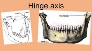
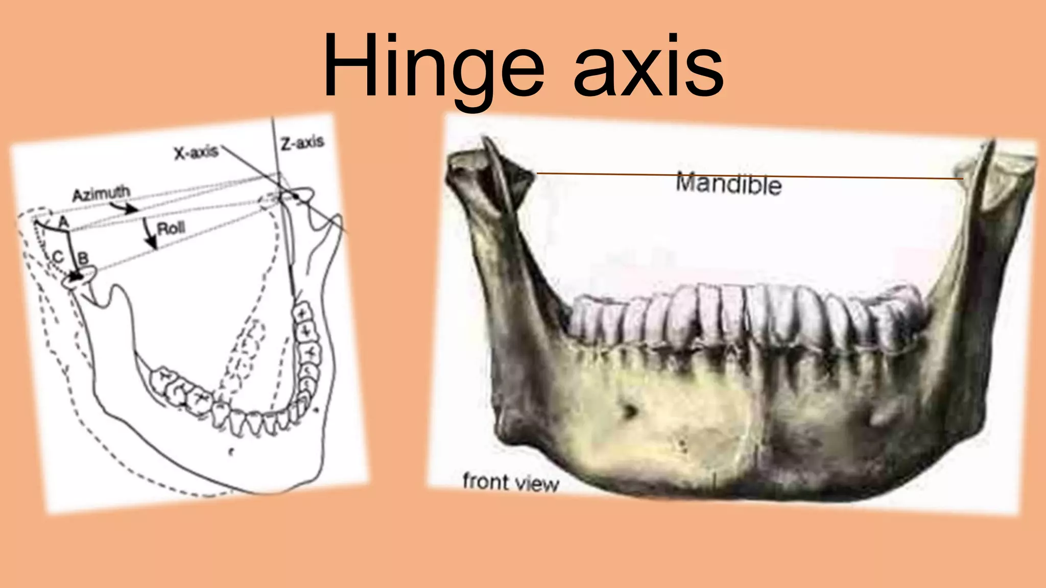
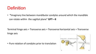
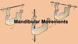
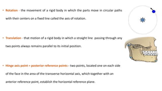
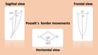
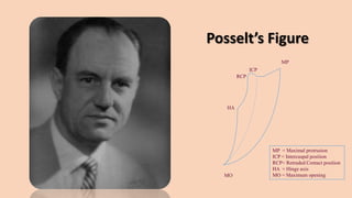


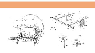
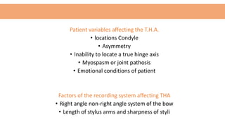


The hinge axis is an imaginary line around which the mandible rotates in the sagittal plane. There are various theories on the location and nature of the hinge axis. Methods to locate it include arbitrary, kinematic, and modified techniques. Locating the hinge axis clinically is important for correctly recording centric relation and transferring jaw movements to an articulator. However, there are many patient and recording system variables that can affect the accuracy of hinge axis location.


![PERI-PROSTHETIC FRACTURE NAIL-PLATE CONSTRUCT [NPC].pptx](https://cdn.slidesharecdn.com/ss_thumbnails/drarunkumardrmohamedashrafperiprostheticfrasturenail-plateconstructnpc-260209164459-7e9d15a1-thumbnail.jpg?width=640&height=640&fit=bounds)


